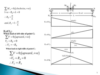
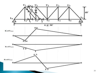
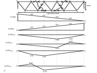
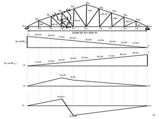
An influence line shows the variation of shear, moment, reaction, or member stress in a structure due to a moving unit load. It is constructed by plotting the value of the specific function as a unit load is moved along the structure.
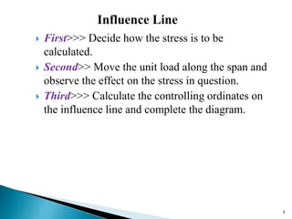
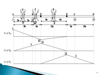
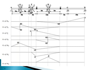
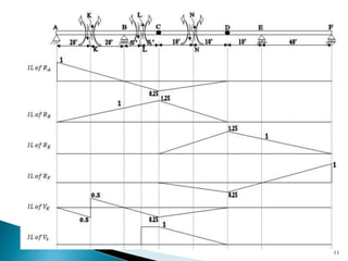
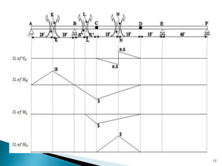
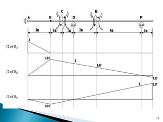
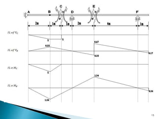
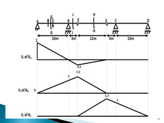
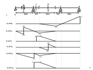
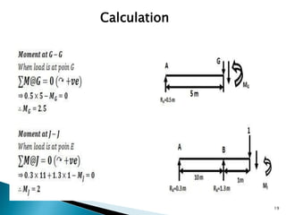
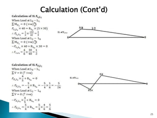
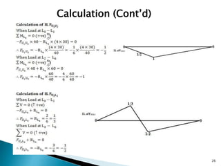
Influence lines for determinate structures are always straight lines. To construct an influence line, the effect of a unit load is observed as it is moved along the span, and the controlling ordinates are calculated and plotted.
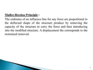
The Muller-Breslau principle states that the ordinates of an influence line are proportional to the deflected shape of the structure if the capacity for a specific force is removed and an equivalent displacement is introduced.