Downloaded 329 times

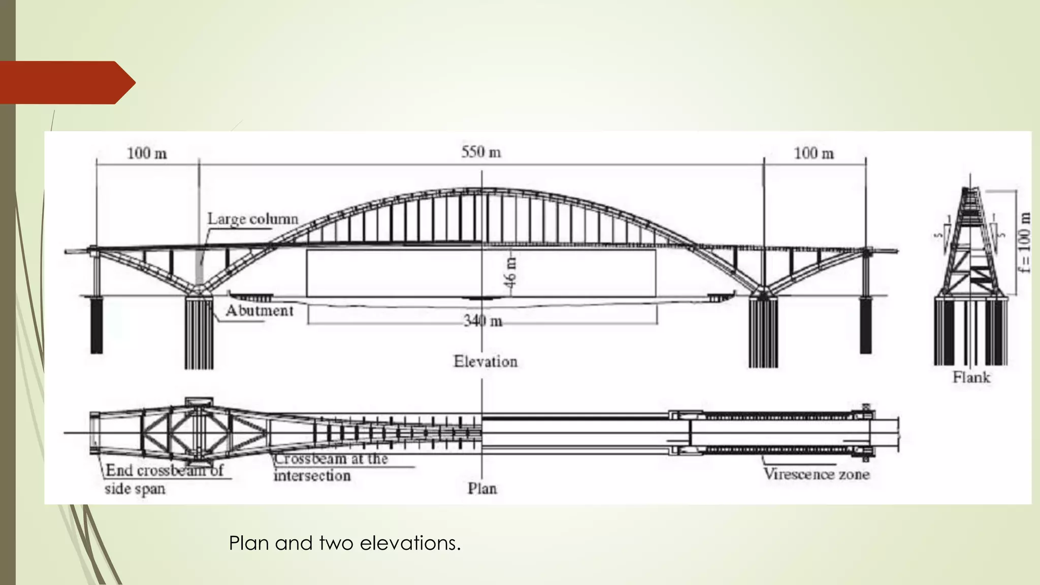
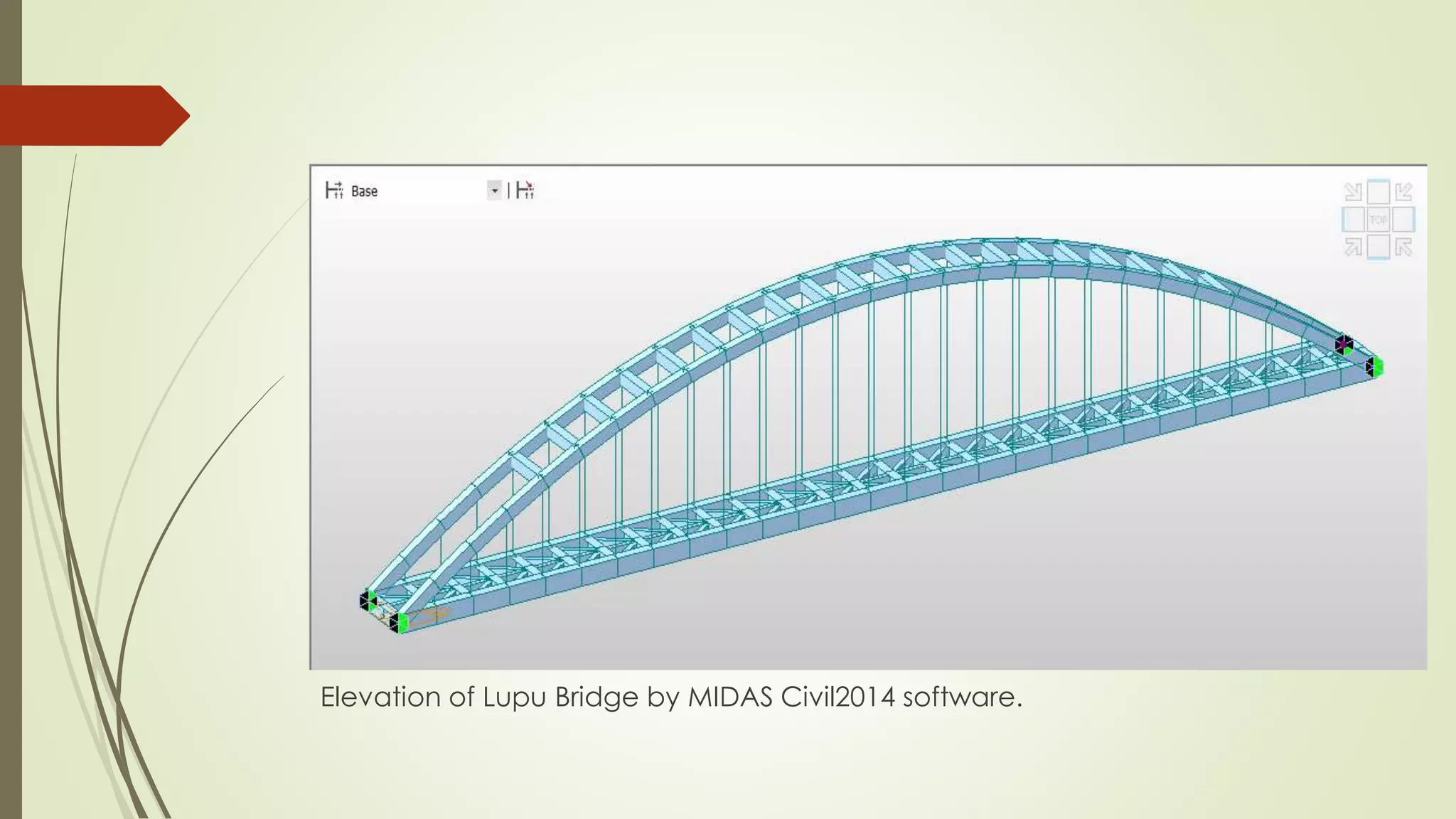


The Lupu Bridge in Shanghai, China is a steel box section tied arch bridge with a main span of 550m, making it the largest arch bridge in the world when it was completed. A tied arch bridge design was used because the ground conditions on either side of the river were unsuitable for the large forces from a normal arch bridge. The bridge was analyzed using structural analysis software to determine member forces and deformations under load. The bridge is an impressive engineering feat that helped advance Chinese bridge engineering.


