Downloaded 366 times

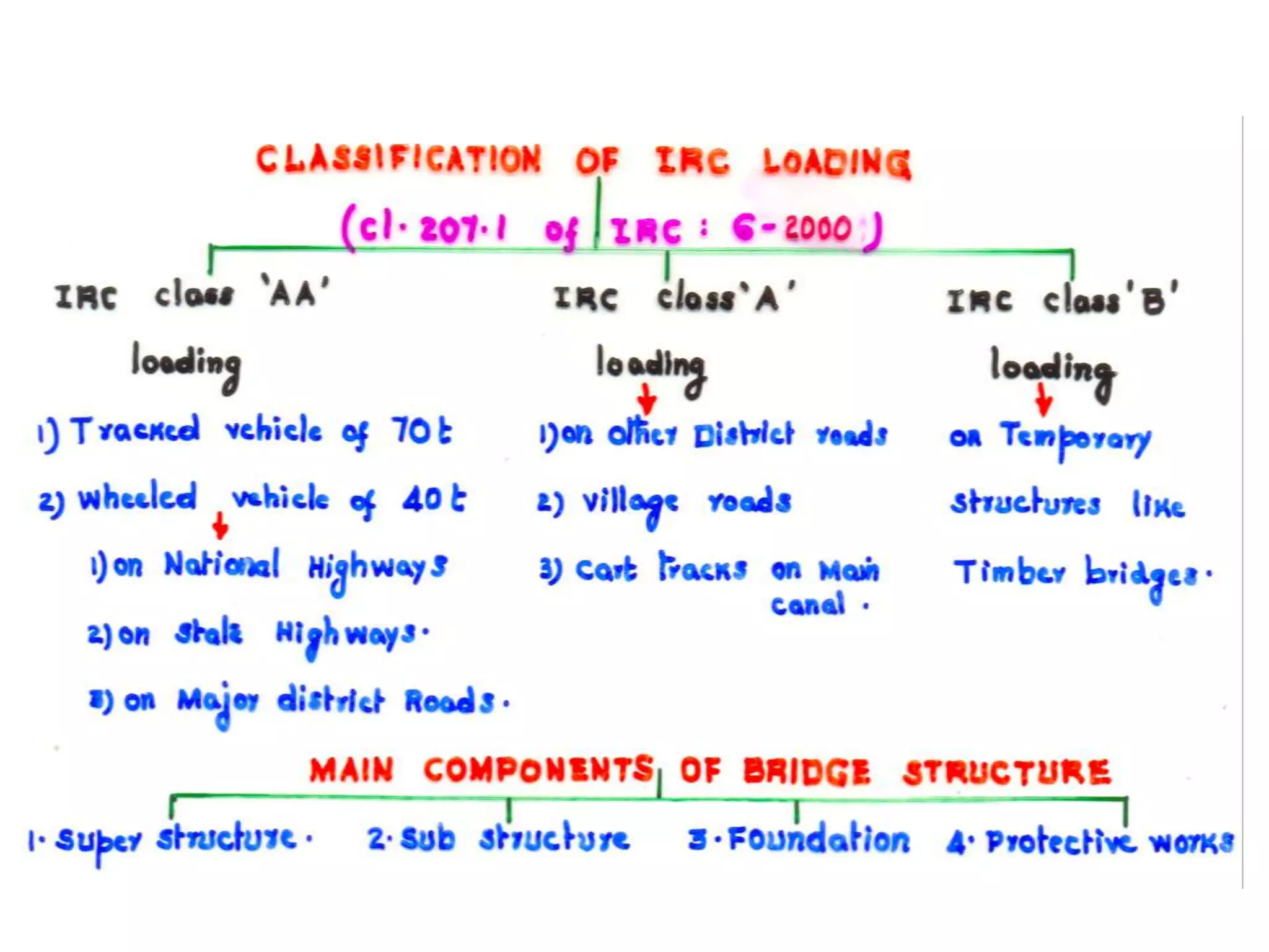
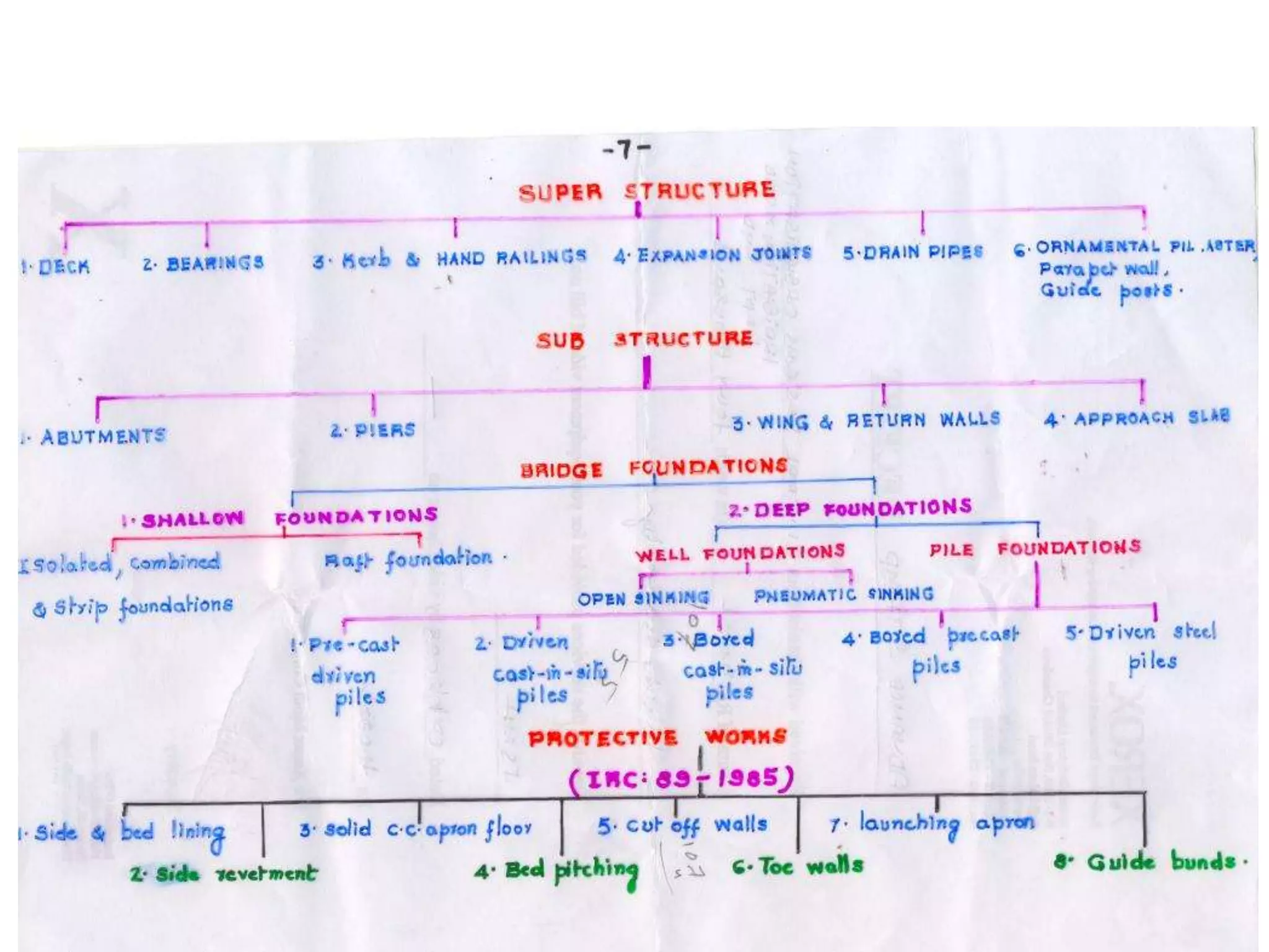
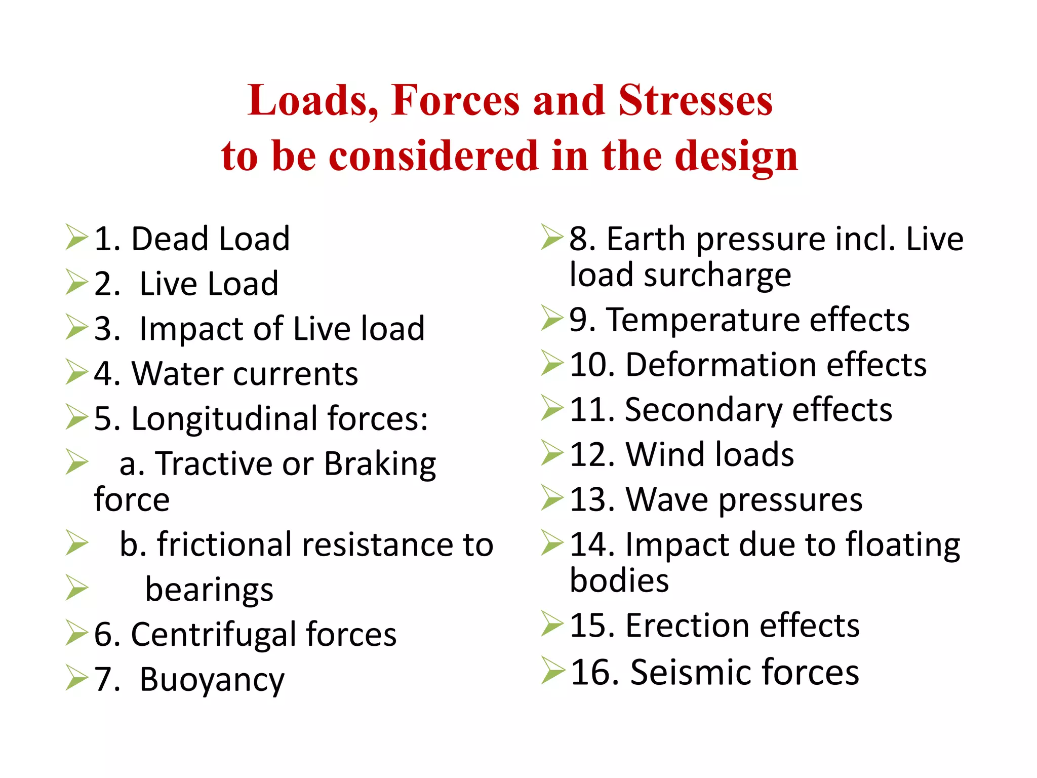
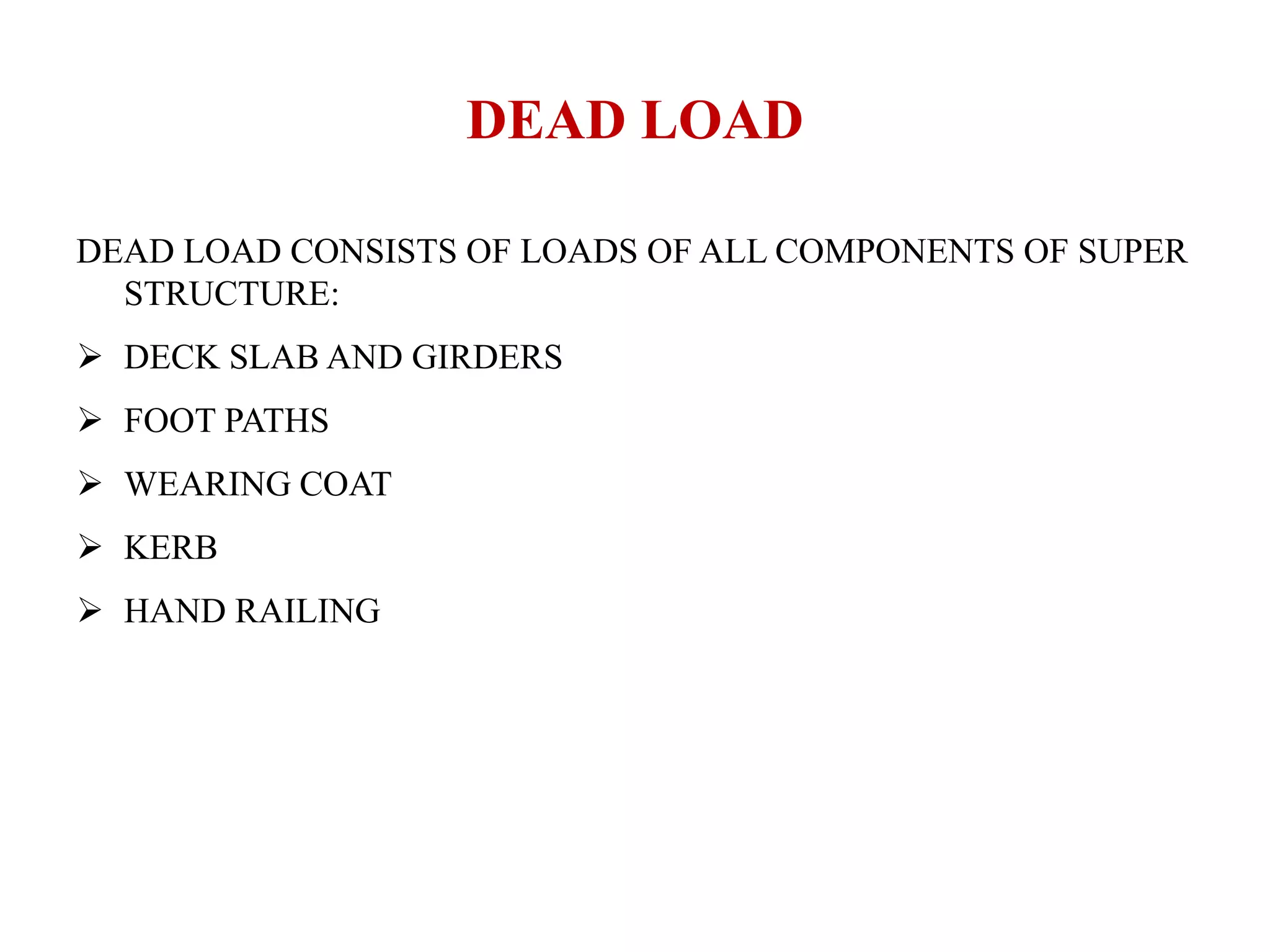


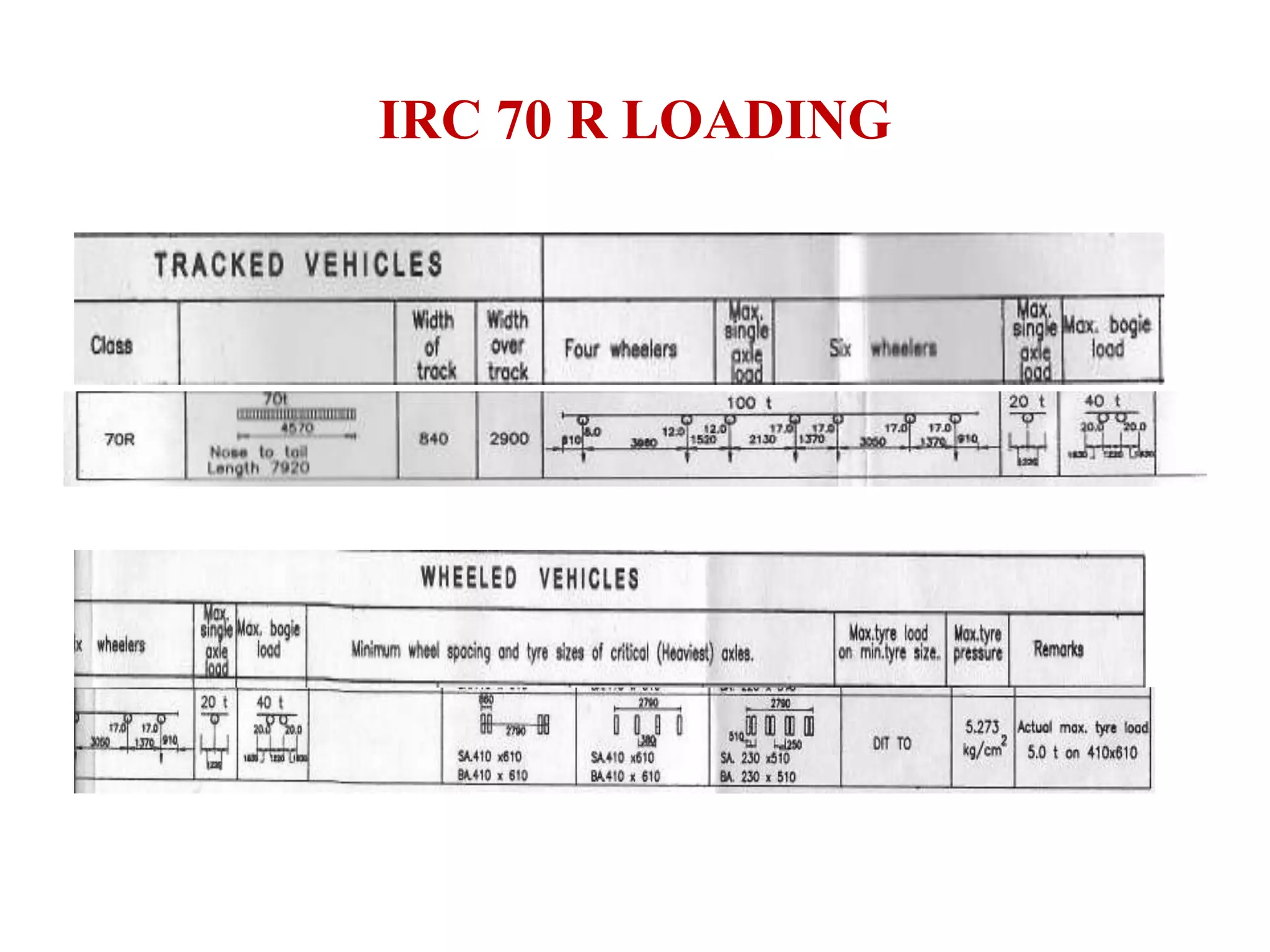
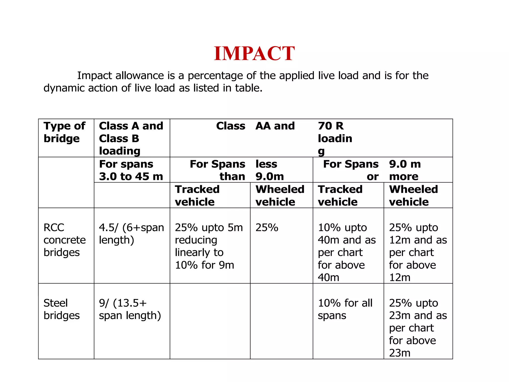

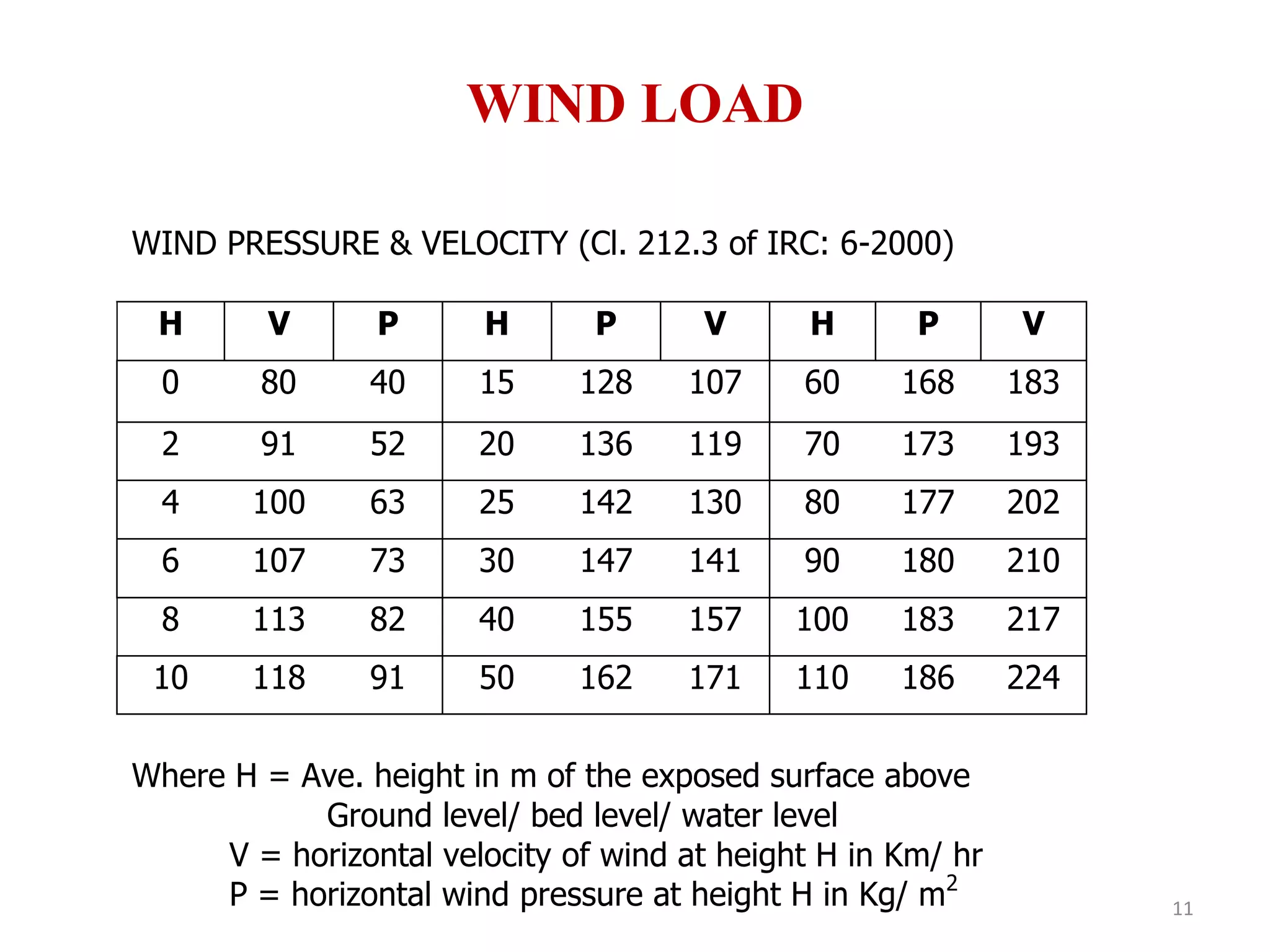


This document outlines various load types that must be considered in bridge design, including: 1. Dead loads from structural components like deck slabs, girders, and railings. 2. Live loads according to Indian Road Congress (IRC) standards, including Class A and 70R loadings. 3. Impact allowance as a percentage of live load to account for dynamic effects, ranging from 10-25% depending on span length and vehicle type. 4. Other loads such as wind loads, which are dependent on average height and wind velocity, and seismic forces. A table provides wind pressure and velocity values.