This document discusses the analysis of prestressed concrete elements under flexure. It begins by introducing prestressing and the assumptions made in the analysis. It then describes three concepts used to analyze PSC elements: the stress concept, force concept, and load balancing concept. Several examples are provided to demonstrate calculating stresses at transfer and service stages using the stress concept. The examples solve for stresses, prestressing force, eccentricity, and live load capacity given various beam properties and loading conditions.
Design of PrestressedConcrete Elements
Analysis of PSC sections for Flexure
By: Prof. M.Manjunath
Dept. of Civil Engineering
KLE Dr. M.S. Sheshgiri College of Engg. & Tech.
Belagavi
Dr. M.Manjunath
1
2.
Analysis of PSCSections under Flexure
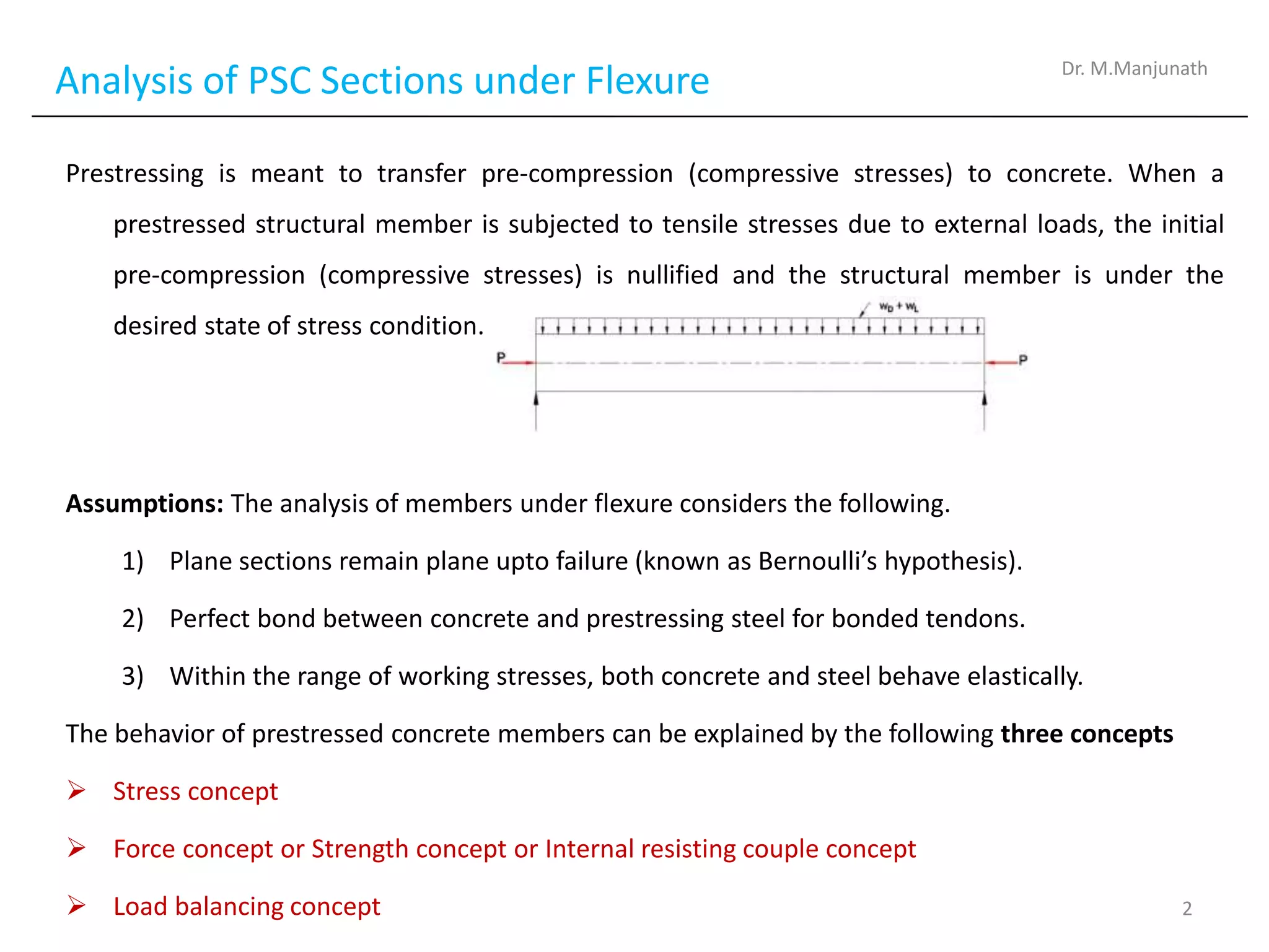
Prestressing is meant to transfer pre-compression (compressive stresses) to concrete. When a
prestressed structural member is subjected to tensile stresses due to external loads, the initial
pre-compression (compressive stresses) is nullified and the structural member is under the
desired state of stress condition.
Assumptions: The analysis of members under flexure considers the following.
1) Plane sections remain plane upto failure (known as Bernoulli’s hypothesis).
2) Perfect bond between concrete and prestressing steel for bonded tendons.
3) Within the range of working stresses, both concrete and steel behave elastically.
The behavior of prestressed concrete members can be explained by the following three concepts
Stress concept
Force concept or Strength concept or Internal resisting couple concept
Load balancing concept
Dr. M.Manjunath
2
3.
Analysis of PSCSections under Flexure
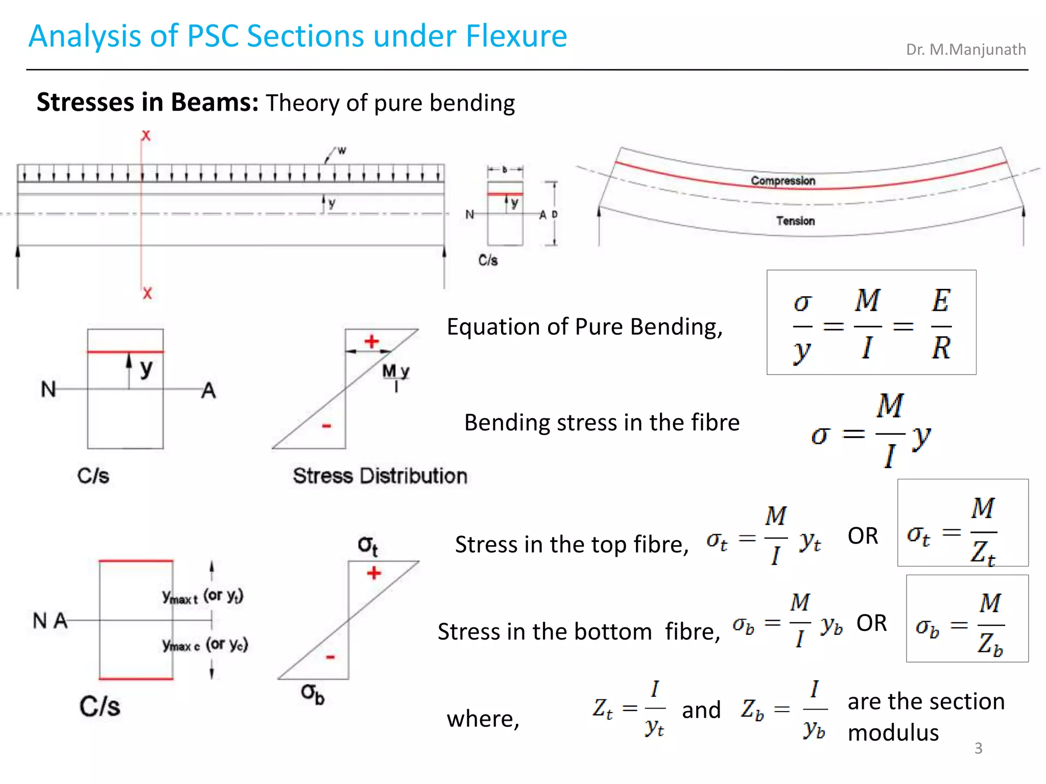
Stresses in Beams: Theory of pure bending
Bending stress in the fibre
Stress in the top fibre,
Stress in the bottom fibre,
where,
are the section
modulus
OR
OR
and
Equation of Pure Bending,
Dr. M.Manjunath
3
4.
Analysis of PSCSections under Flexure
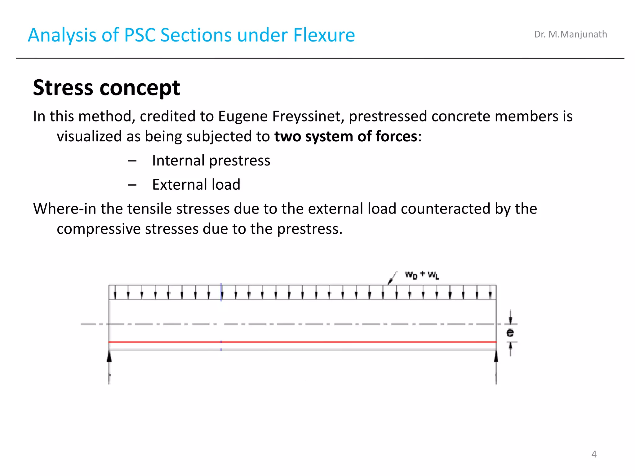
Stress concept
In this method, credited to Eugene Freyssinet, prestressed concrete members is
visualized as being subjected to two system of forces:
– Internal prestress
– External load
Where-in the tensile stresses due to the external load counteracted by the
compressive stresses due to the prestress.
Dr. M.Manjunath
4
5.
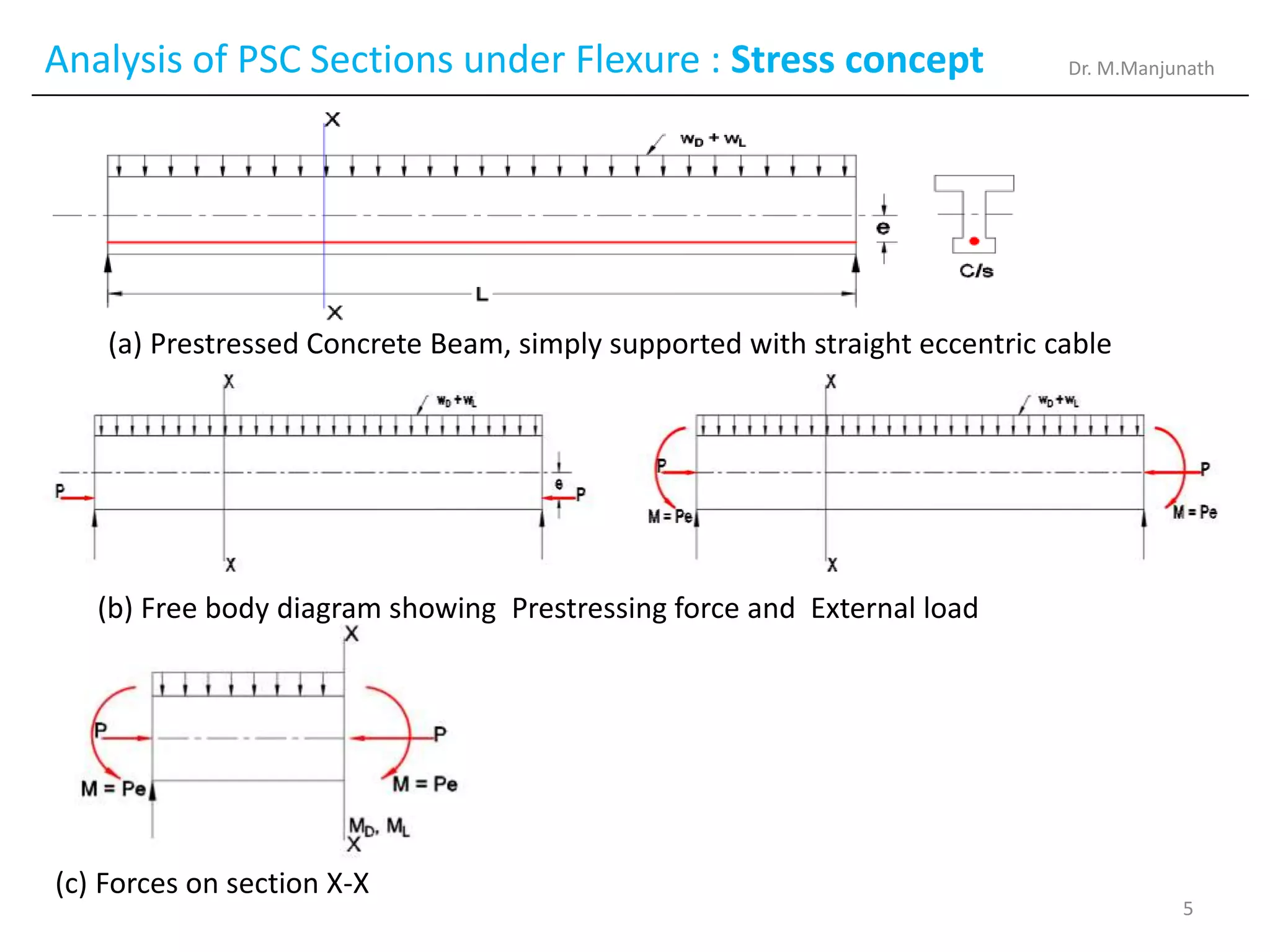
Analysis of PSCSections under Flexure : Stress concept
(a) Prestressed Concrete Beam, simply supported with straight eccentric cable
(b) Free body diagram showing Prestressing force and External load
(c) Forces on section X-X
Dr. M.Manjunath
5
6.
Analysis of PSCSections under Flexure : Stress concept
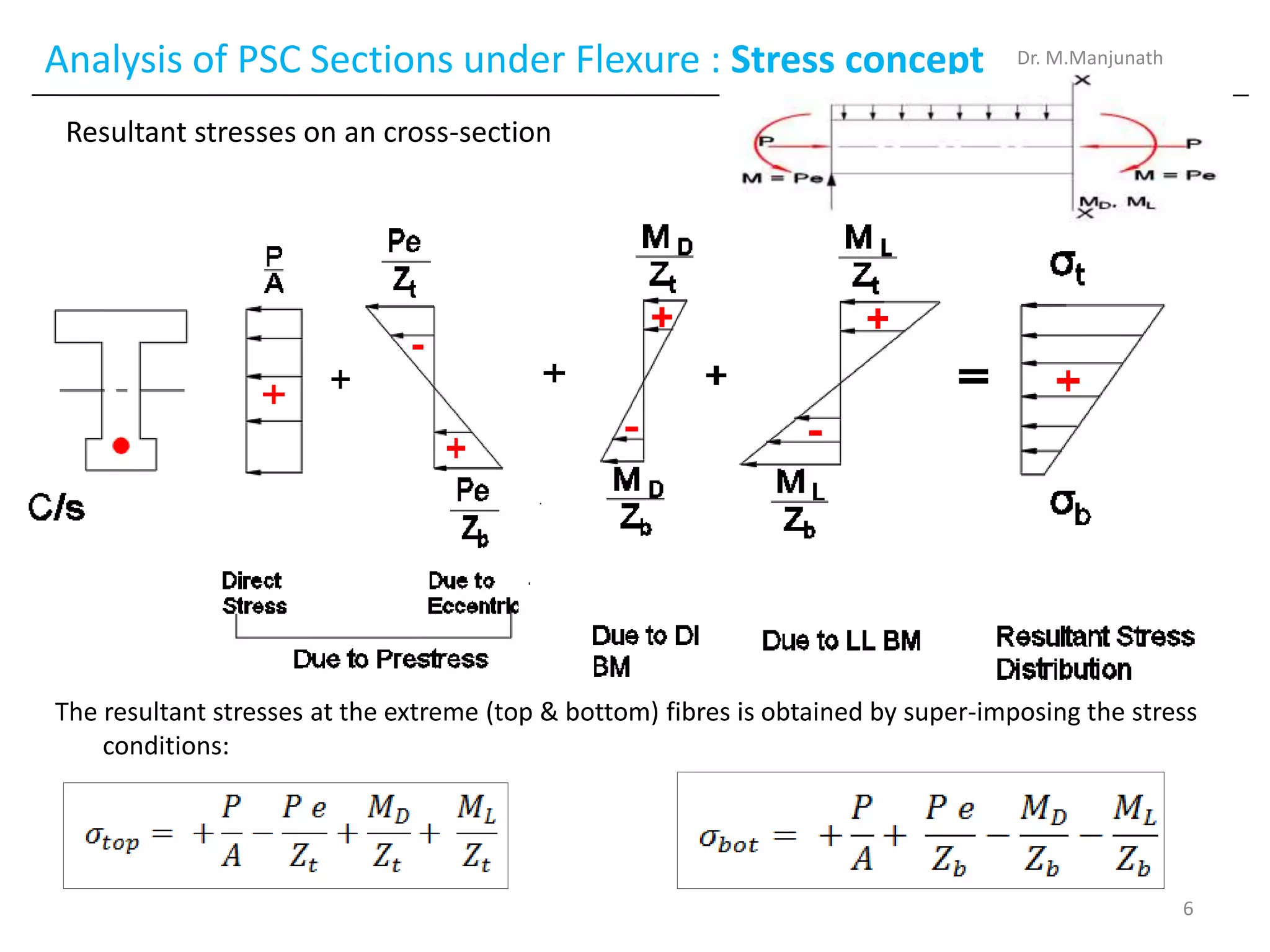
Resultant stresses on an cross-section
Dr. M.Manjunath
The resultant stresses at the extreme (top & bottom) fibres is obtained by super-imposing the stress
conditions:
6
7.
Analysis of PSCSections under Flexure : Stress concept
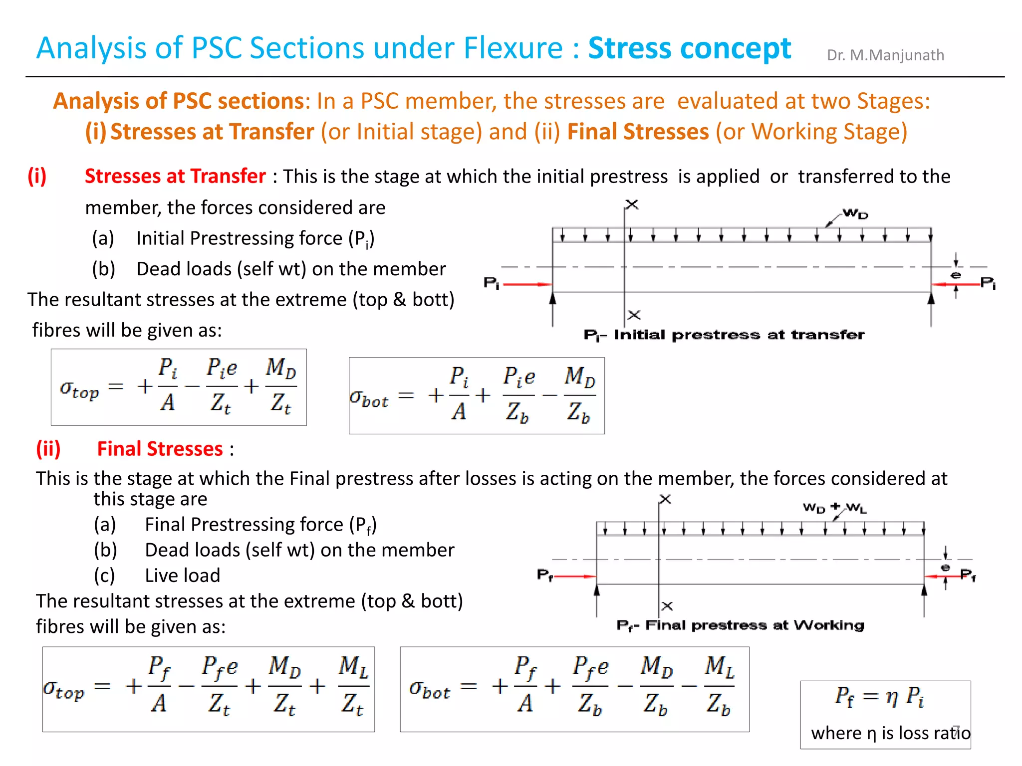
(ii) Final Stresses :
This is the stage at which the Final prestress after losses is acting on the member, the forces considered at
this stage are
(a) Final Prestressing force (Pf)
(b) Dead loads (self wt) on the member
(c) Live load
The resultant stresses at the extreme (top & bott)
fibres will be given as:
(i) Stresses at Transfer : This is the stage at which the initial prestress is applied or transferred to the
member, the forces considered are
(a) Initial Prestressing force (Pi)
(b) Dead loads (self wt) on the member
The resultant stresses at the extreme (top & bott)
fibres will be given as:
where η is loss ratio
Dr. M.Manjunath
Analysis of PSC sections: In a PSC member, the stresses are evaluated at two Stages:
(i)Stresses at Transfer (or Initial stage) and (ii) Final Stresses (or Working Stage)
7
8.
Analysis of PSCSections under Flexure : Stress concept
Numerical Examples:
Problem types:
Type 1: Given data about the beam : Span, support condition, C/s, LL, Prestressing force, profile & eccentricity
Required: The resultant stresses at either Transfer or final or both.
Type 2: Given : Span, support condition, C/s, LL and Stress condition at either Transfer or final or both
Required: Either Prestressing force or eccentricity or both.
Type 3: Given : Span, support condition, C/s, Prestressing force and Stress condition at Transfer or final or both
Required: Live load on the beam.
Example 1:
An unsymmetrical Beam is used to support an imposed load of 2Kn/m over a span of 8m. The
sectional details are top flange 300mm wide and 60mm thick, bottom flange 100mm wide and 60
mm thick, thickness of web 80mm, overall depth of beam = 400mm. At the centre of the span, the
effective prestresssing force of 100 kN is located at 50mm from the soffit of the beam. Estimate the
stresses at the centre of span section of the beam for the following load condition: (a) Prestress +
Self weight (b) Prestress + Self weight + Live load.
Soln:
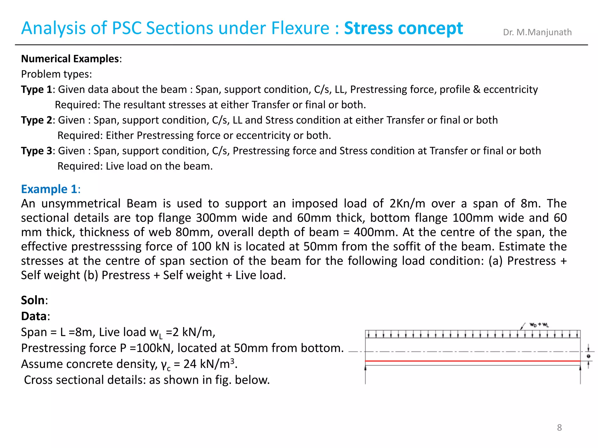
Data:
Span = L =8m, Live load wL =2 kN/m,
Prestressing force P =100kN, located at 50mm from bottom.
Assume concrete density, γc = 24 kN/m3.
Cross sectional details: as shown in fig. below.
Dr. M.Manjunath
8
9.
Analysis of PSCSections under Flexure : Stress concept
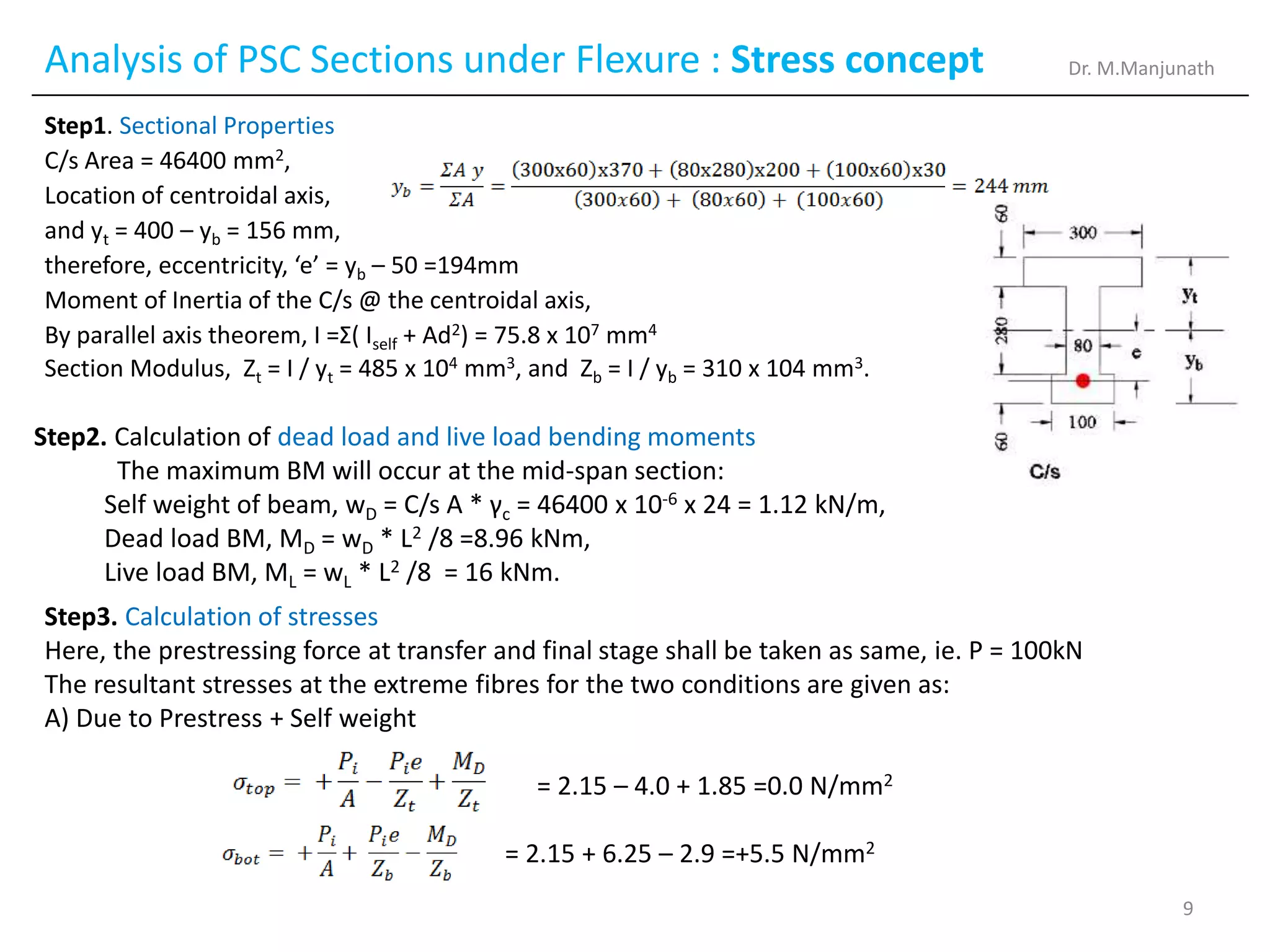
Step1. Sectional Properties
C/s Area = 46400 mm2,
Location of centroidal axis,
and yt = 400 – yb = 156 mm,
therefore, eccentricity, ‘e’ = yb – 50 =194mm
Moment of Inertia of the C/s @ the centroidal axis,
By parallel axis theorem, I =Σ( Iself + Ad2) = 75.8 x 107 mm4
Section Modulus, Zt = I / yt = 485 x 104 mm3, and Zb = I / yb = 310 x 104 mm3.
Step2. Calculation of dead load and live load bending moments
The maximum BM will occur at the mid-span section:
Self weight of beam, wD = C/s A * γc = 46400 x 10-6 x 24 = 1.12 kN/m,
Dead load BM, MD = wD * L2 /8 =8.96 kNm,
Live load BM, ML = wL * L2 /8 = 16 kNm.
Step3. Calculation of stresses
Here, the prestressing force at transfer and final stage shall be taken as same, ie. P = 100kN
The resultant stresses at the extreme fibres for the two conditions are given as:
A) Due to Prestress + Self weight
= 2.15 – 4.0 + 1.85 =0.0 N/mm2
= 2.15 + 6.25 – 2.9 =+5.5 N/mm2
Dr. M.Manjunath
9
10.
Analysis of PSCSections under Flexure : Stress concept
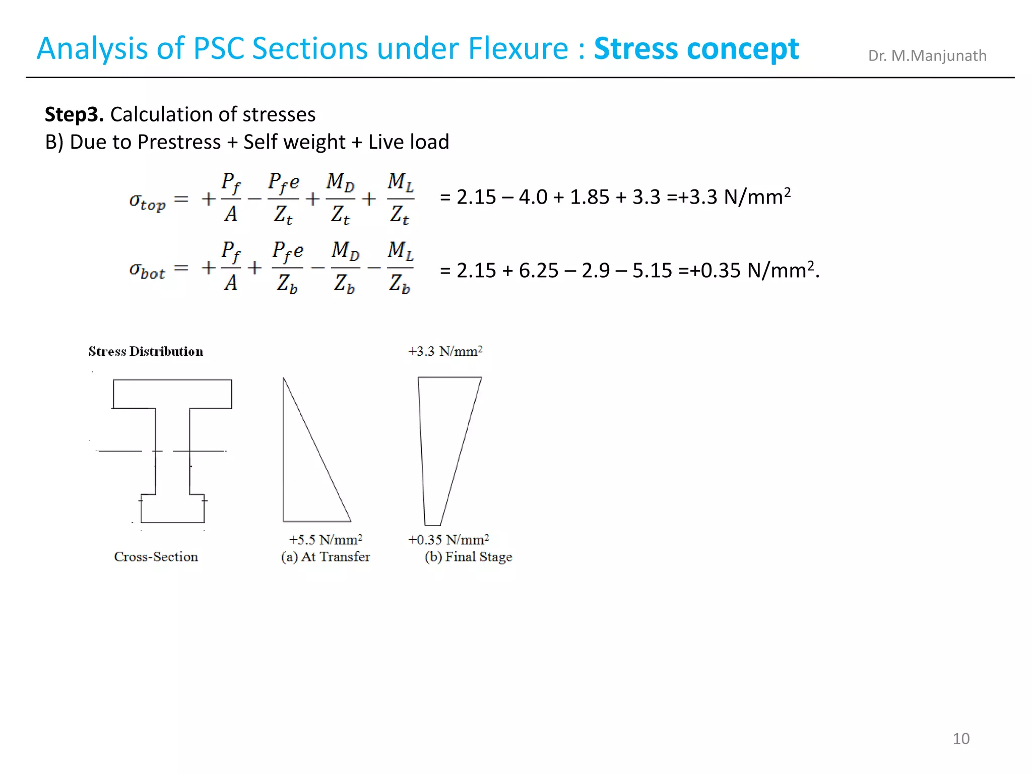
Step3. Calculation of stresses
B) Due to Prestress + Self weight + Live load
= 2.15 – 4.0 + 1.85 + 3.3 =+3.3 N/mm2
= 2.15 + 6.25 – 2.9 – 5.15 =+0.35 N/mm2.
Dr. M.Manjunath
10
11.
Analysis of PSCSections under Flexure : Stress concept
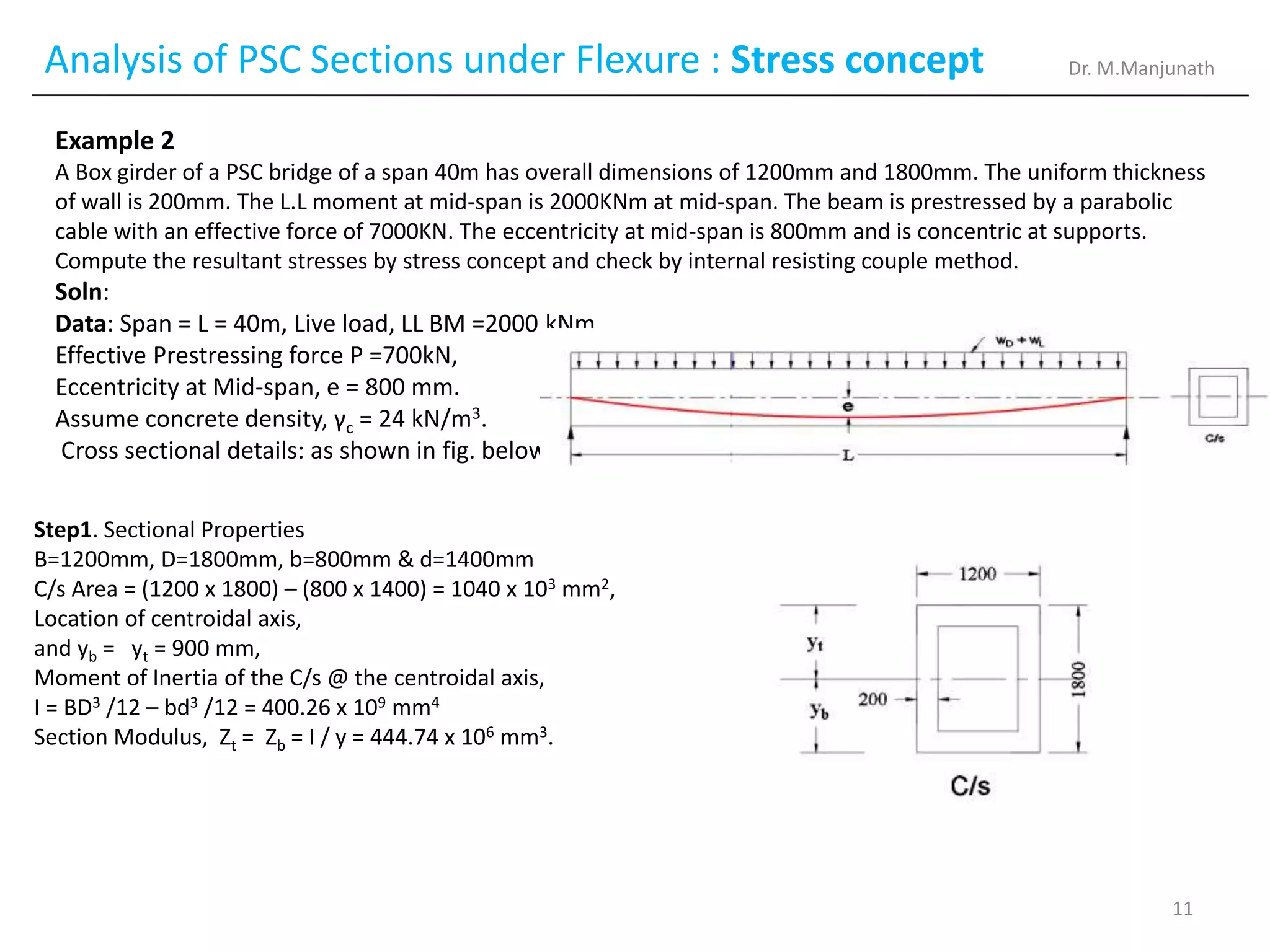
Example 2
A Box girder of a PSC bridge of a span 40m has overall dimensions of 1200mm and 1800mm. The uniform thickness
of wall is 200mm. The L.L moment at mid-span is 2000KNm at mid-span. The beam is prestressed by a parabolic
cable with an effective force of 7000KN. The eccentricity at mid-span is 800mm and is concentric at supports.
Compute the resultant stresses by stress concept and check by internal resisting couple method.
Soln:
Data: Span = L = 40m, Live load, LL BM =2000 kNm,
Effective Prestressing force P =700kN,
Eccentricity at Mid-span, e = 800 mm.
Assume concrete density, γc = 24 kN/m3.
Cross sectional details: as shown in fig. below.
Step1. Sectional Properties
B=1200mm, D=1800mm, b=800mm & d=1400mm
C/s Area = (1200 x 1800) – (800 x 1400) = 1040 x 103 mm2,
Location of centroidal axis,
and yb = yt = 900 mm,
Moment of Inertia of the C/s @ the centroidal axis,
I = BD3 /12 – bd3 /12 = 400.26 x 109 mm4
Section Modulus, Zt = Zb = I / y = 444.74 x 106 mm3.
Dr. M.Manjunath
11
12.
Analysis of PSCSections under Flexure : Stress concept
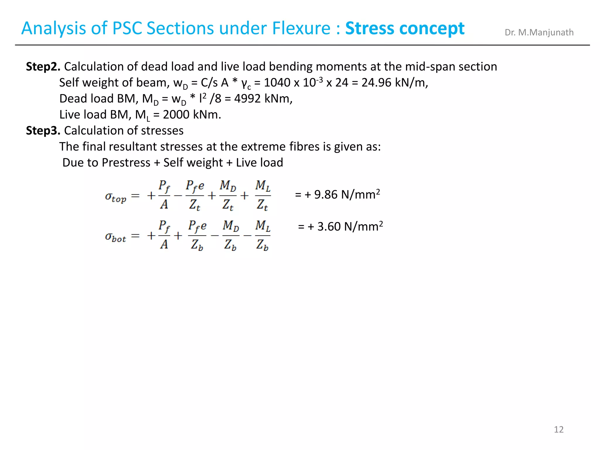
Step2. Calculation of dead load and live load bending moments at the mid-span section
Self weight of beam, wD = C/s A * γc = 1040 x 10-3 x 24 = 24.96 kN/m,
Dead load BM, MD = wD * l2 /8 = 4992 kNm,
Live load BM, ML = 2000 kNm.
Step3. Calculation of stresses
The final resultant stresses at the extreme fibres is given as:
Due to Prestress + Self weight + Live load
= + 9.86 N/mm2
= + 3.60 N/mm2
Dr. M.Manjunath
12
13.
Analysis of PSCSections under Flexure : Stress concept
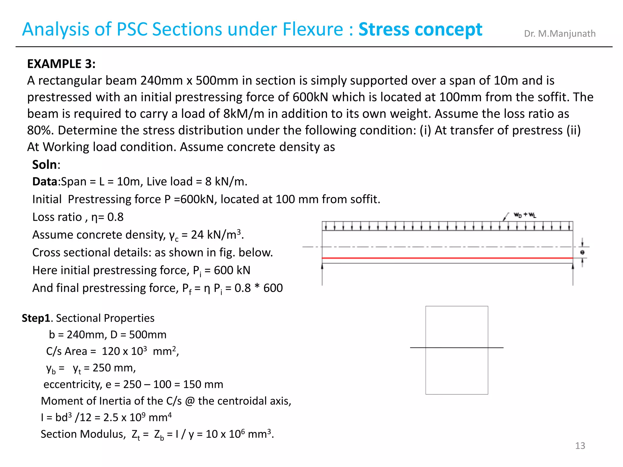
EXAMPLE 3:
A rectangular beam 240mm x 500mm in section is simply supported over a span of 10m and is
prestressed with an initial prestressing force of 600kN which is located at 100mm from the soffit. The
beam is required to carry a load of 8kM/m in addition to its own weight. Assume the loss ratio as
80%. Determine the stress distribution under the following condition: (i) At transfer of prestress (ii)
At Working load condition. Assume concrete density as
Step1. Sectional Properties
b = 240mm, D = 500mm
C/s Area = 120 x 103 mm2,
yb = yt = 250 mm,
eccentricity, e = 250 – 100 = 150 mm
Moment of Inertia of the C/s @ the centroidal axis,
I = bd3 /12 = 2.5 x 109 mm4
Section Modulus, Zt = Zb = I / y = 10 x 106 mm3.
Soln:
Data:Span = L = 10m, Live load = 8 kN/m.
Initial Prestressing force P =600kN, located at 100 mm from soffit.
Loss ratio , η= 0.8
Assume concrete density, γc = 24 kN/m3.
Cross sectional details: as shown in fig. below.
Here initial prestressing force, Pi = 600 kN
And final prestressing force, Pf = η Pi = 0.8 * 600
Dr. M.Manjunath
13
14.
Analysis of PSCSections under Flexure : Stress concept
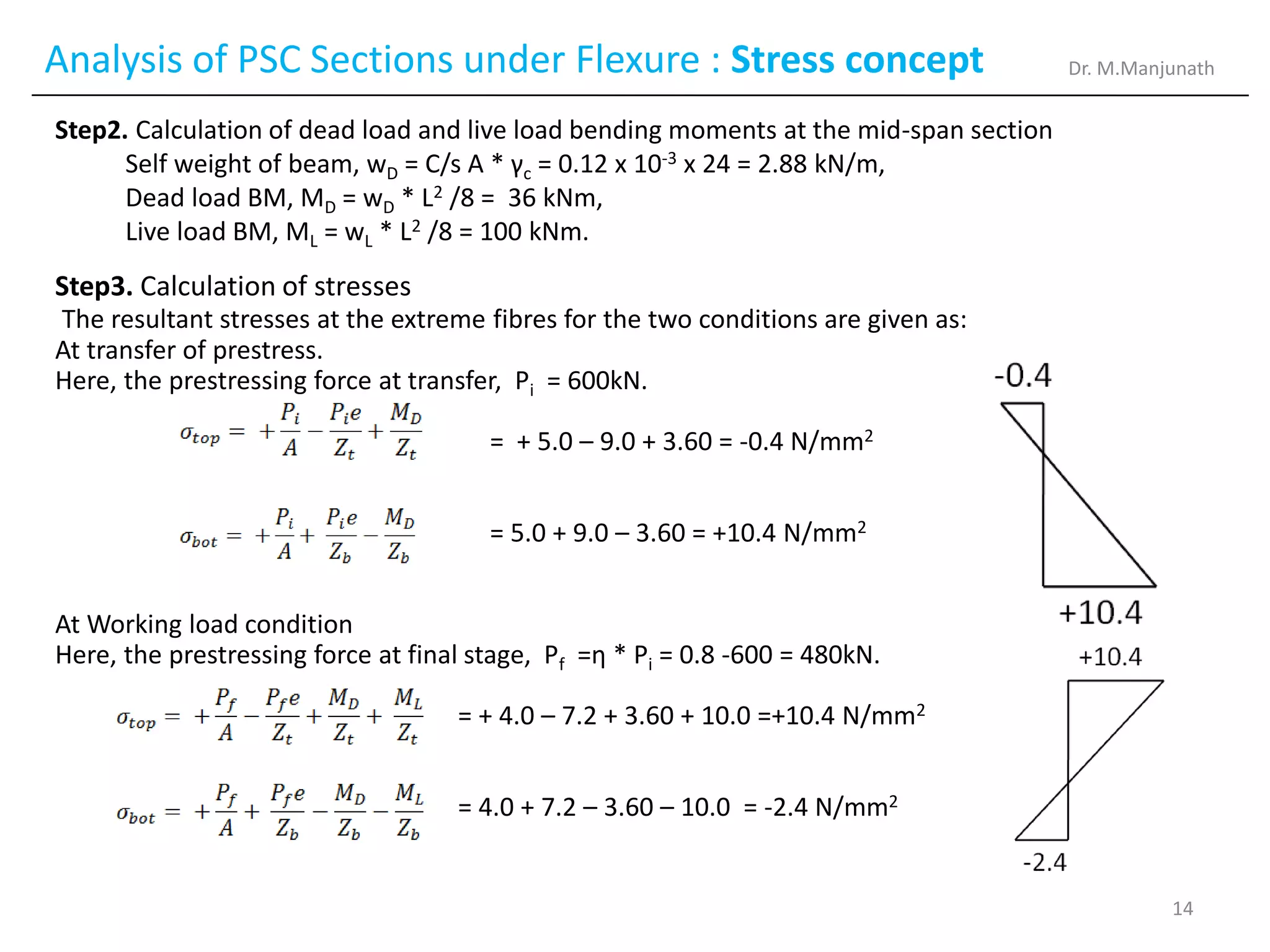
Step2. Calculation of dead load and live load bending moments at the mid-span section
Self weight of beam, wD = C/s A * γc = 0.12 x 10-3 x 24 = 2.88 kN/m,
Dead load BM, MD = wD * L2 /8 = 36 kNm,
Live load BM, ML = wL * L2 /8 = 100 kNm.
Step3. Calculation of stresses
The resultant stresses at the extreme fibres for the two conditions are given as:
At transfer of prestress.
Here, the prestressing force at transfer, Pi = 600kN.
= + 5.0 – 9.0 + 3.60 = -0.4 N/mm2
= 5.0 + 9.0 – 3.60 = +10.4 N/mm2
At Working load condition
Here, the prestressing force at final stage, Pf =η * Pi = 0.8 -600 = 480kN.
= + 4.0 – 7.2 + 3.60 + 10.0 =+10.4 N/mm2
= 4.0 + 7.2 – 3.60 – 10.0 = -2.4 N/mm2
Dr. M.Manjunath
14
15.
Analysis of PSCSections under Flexure : Stress concept
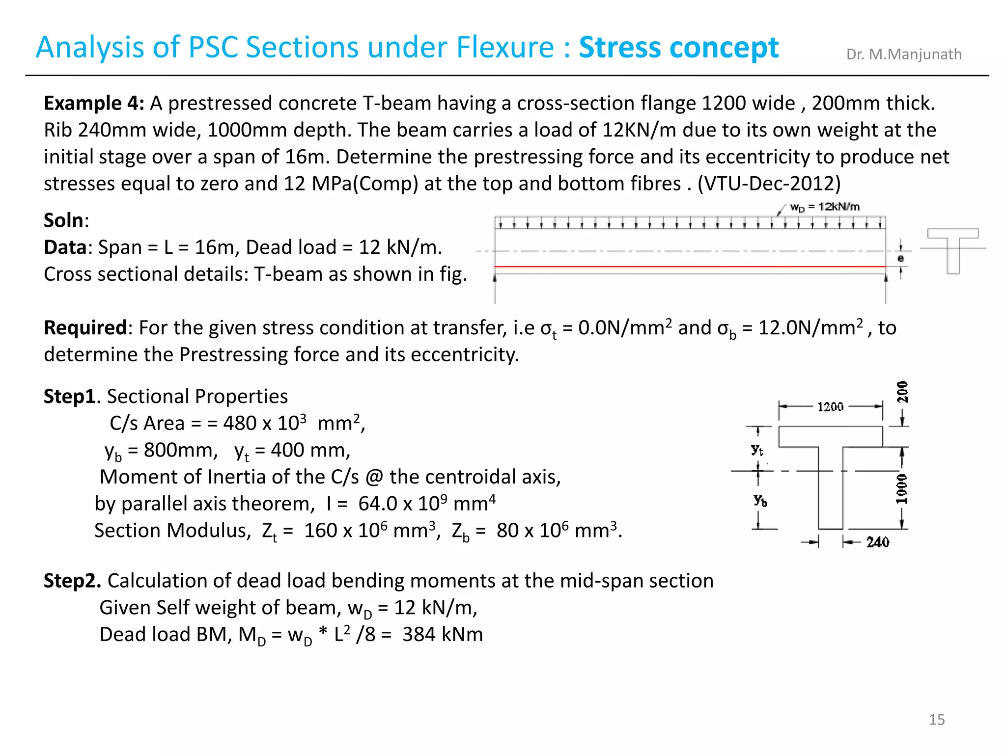
Example 4: A prestressed concrete T-beam having a cross-section flange 1200 wide , 200mm thick.
Rib 240mm wide, 1000mm depth. The beam carries a load of 12KN/m due to its own weight at the
initial stage over a span of 16m. Determine the prestressing force and its eccentricity to produce net
stresses equal to zero and 12 MPa(Comp) at the top and bottom fibres . (VTU-Dec-2012)
Soln:
Data: Span = L = 16m, Dead load = 12 kN/m.
Cross sectional details: T-beam as shown in fig.
Required: For the given stress condition at transfer, i.e σt = 0.0N/mm2 and σb = 12.0N/mm2 , to
determine the Prestressing force and its eccentricity.
Step1. Sectional Properties
C/s Area = = 480 x 103 mm2,
yb = 800mm, yt = 400 mm,
Moment of Inertia of the C/s @ the centroidal axis,
by parallel axis theorem, I = 64.0 x 109 mm4
Section Modulus, Zt = 160 x 106 mm3, Zb = 80 x 106 mm3.
Step2. Calculation of dead load bending moments at the mid-span section
Given Self weight of beam, wD = 12 kN/m,
Dead load BM, MD = wD * L2 /8 = 384 kNm
Dr. M.Manjunath
15
16.
Analysis of PSCSections under Flexure : Stress concept
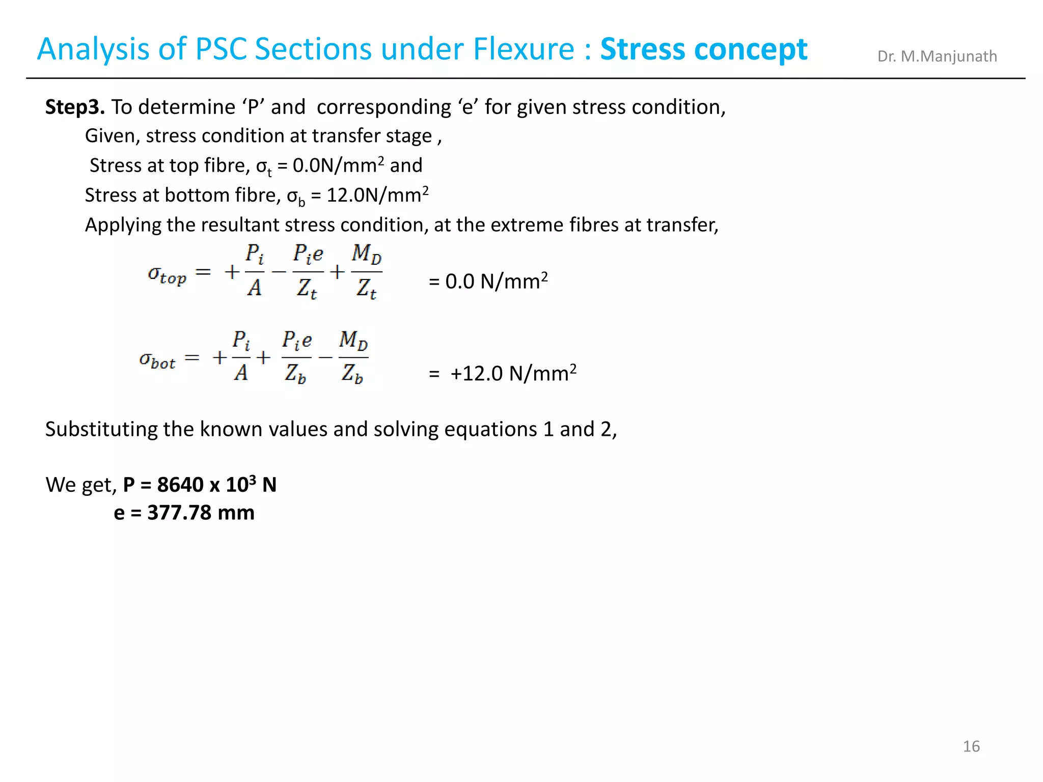
Step3. To determine ‘P’ and corresponding ‘e’ for given stress condition,
Given, stress condition at transfer stage ,
Stress at top fibre, σt = 0.0N/mm2 and
Stress at bottom fibre, σb = 12.0N/mm2
Applying the resultant stress condition, at the extreme fibres at transfer,
= 0.0 N/mm2
= +12.0 N/mm2
Substituting the known values and solving equations 1 and 2,
We get, P = 8640 x 103 N
e = 377.78 mm
Dr. M.Manjunath
16
17.
Analysis of PSCSections under Flexure : Stress concept
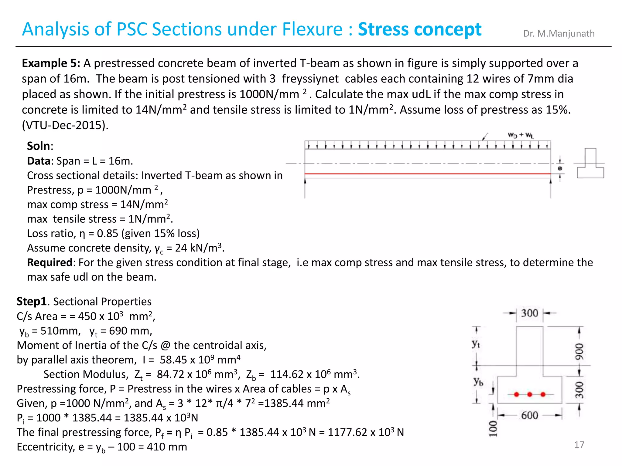
Example 5: A prestressed concrete beam of inverted T-beam as shown in figure is simply supported over a
span of 16m. The beam is post tensioned with 3 freyssiynet cables each containing 12 wires of 7mm dia
placed as shown. If the initial prestress is 1000N/mm 2 . Calculate the max udL if the max comp stress in
concrete is limited to 14N/mm2 and tensile stress is limited to 1N/mm2. Assume loss of prestress as 15%.
(VTU-Dec-2015).
Soln:
Data: Span = L = 16m.
Cross sectional details: Inverted T-beam as shown in fig.
Prestress, p = 1000N/mm 2 ,
max comp stress = 14N/mm2
max tensile stress = 1N/mm2.
Loss ratio, η = 0.85 (given 15% loss)
Assume concrete density, γc = 24 kN/m3.
Required: For the given stress condition at final stage, i.e max comp stress and max tensile stress, to determine the
max safe udl on the beam.
Step1. Sectional Properties
C/s Area = = 450 x 103 mm2,
yb = 510mm, yt = 690 mm,
Moment of Inertia of the C/s @ the centroidal axis,
by parallel axis theorem, I = 58.45 x 109 mm4
Section Modulus, Zt = 84.72 x 106 mm3, Zb = 114.62 x 106 mm3.
Prestressing force, P = Prestress in the wires x Area of cables = p x As
Given, p =1000 N/mm2, and As = 3 * 12* π/4 * 72 =1385.44 mm2
Pi = 1000 * 1385.44 = 1385.44 x 103N
The final prestressing force, Pf = η Pi = 0.85 * 1385.44 x 103 N = 1177.62 x 103 N
Eccentricity, e = yb – 100 = 410 mm
Dr. M.Manjunath
17
18.
Analysis of PSCSections under Flexure : Stress concept
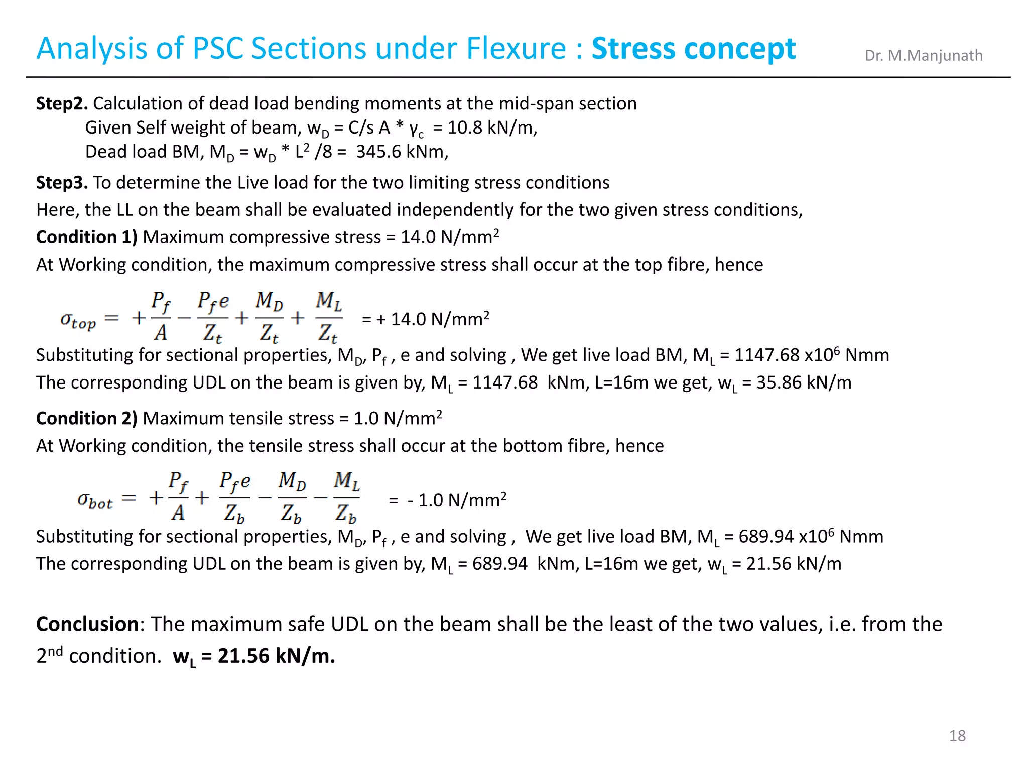
Step2. Calculation of dead load bending moments at the mid-span section
Given Self weight of beam, wD = C/s A * γc = 10.8 kN/m,
Dead load BM, MD = wD * L2 /8 = 345.6 kNm,
Step3. To determine the Live load for the two limiting stress conditions
Here, the LL on the beam shall be evaluated independently for the two given stress conditions,
Condition 1) Maximum compressive stress = 14.0 N/mm2
At Working condition, the maximum compressive stress shall occur at the top fibre, hence
= + 14.0 N/mm2
Substituting for sectional properties, MD, Pf , e and solving , We get live load BM, ML = 1147.68 x106 Nmm
The corresponding UDL on the beam is given by, ML = 1147.68 kNm, L=16m we get, wL = 35.86 kN/m
Condition 2) Maximum tensile stress = 1.0 N/mm2
At Working condition, the tensile stress shall occur at the bottom fibre, hence
= - 1.0 N/mm2
Substituting for sectional properties, MD, Pf , e and solving , We get live load BM, ML = 689.94 x10⁶ Nmm
The corresponding UDL on the beam is given by, ML = 689.94 kNm, L=16m we get, wL = 21.56 kN/m
Conclusion: The maximum safe UDL on the beam shall be the least of the two values, i.e. from the
2nd condition. wL = 21.56 kN/m.
Dr. M.Manjunath
18