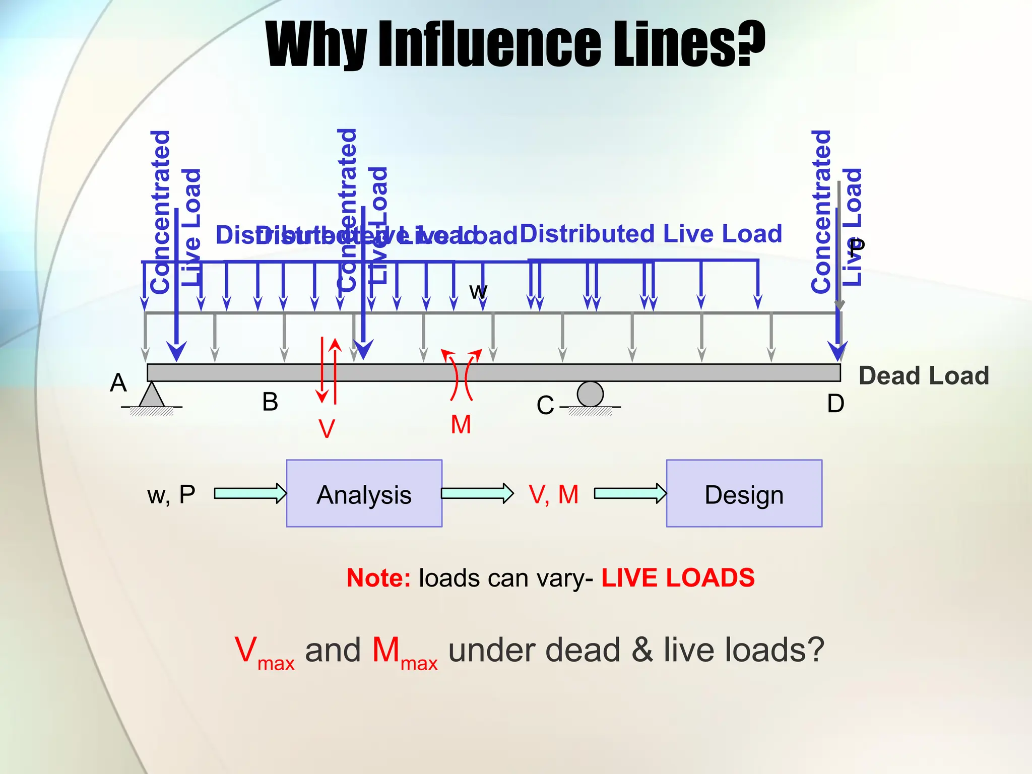
Why Influence Lines?
A
BC D
Dead Load
Concentrated
Live
Load
Concentrated
Live
Load
Concentrated
Live
Load
Distributed Live Load
Distributed Live LoadDistributed Live Load
w
P
V M
Analysis
w, P V, M Design
Note: loads can vary- LIVE LOADS
Vmax and Mmax under dead & live loads?
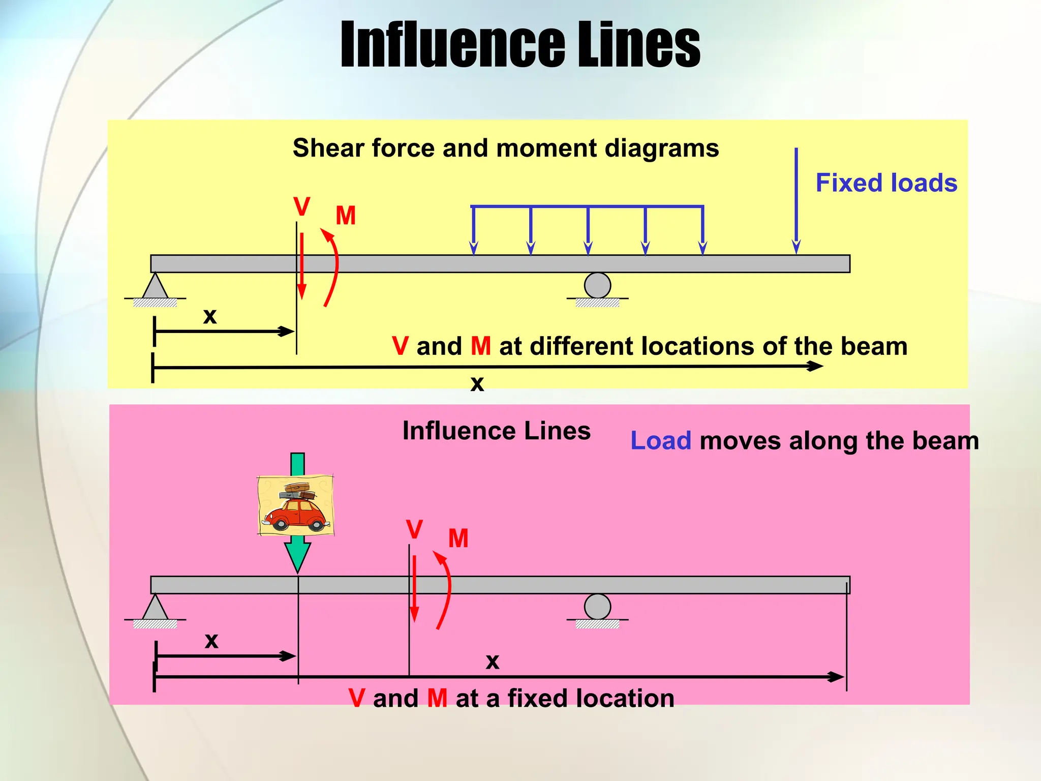
Influence Lines
Influence Lines
Shearforce and moment diagrams
Fixed loads
V M
x
V and M at different locations of the beam
x
V and M at a fixed location
V M
Load moves along the beam
x
x
9.
Influence Lines
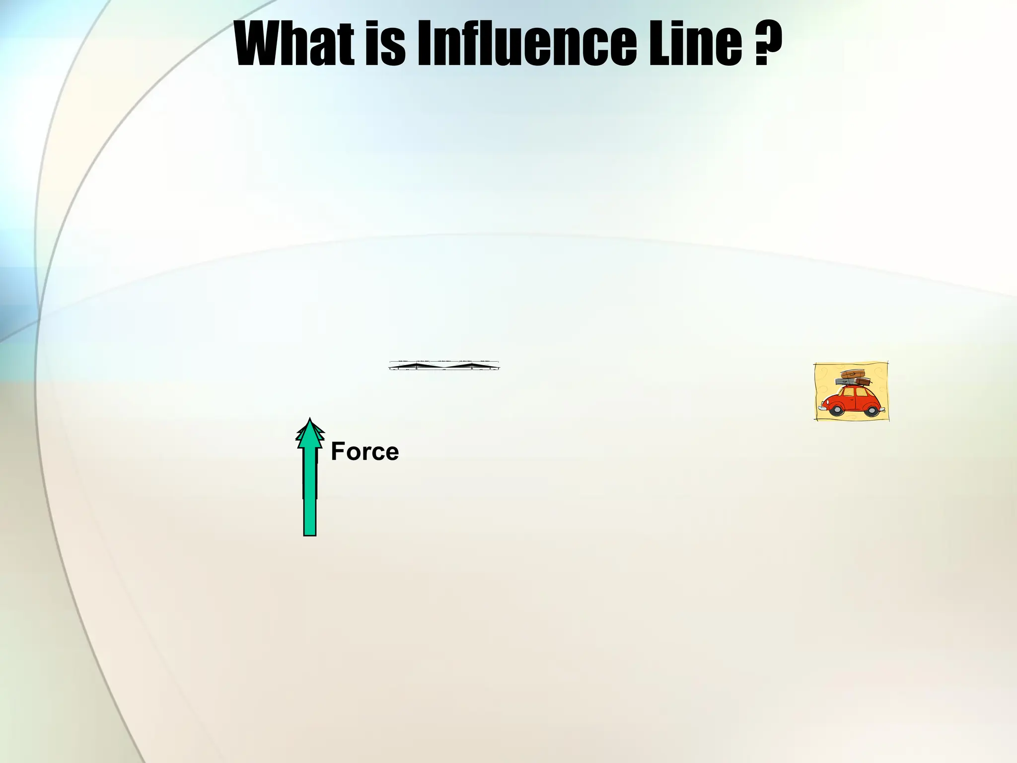
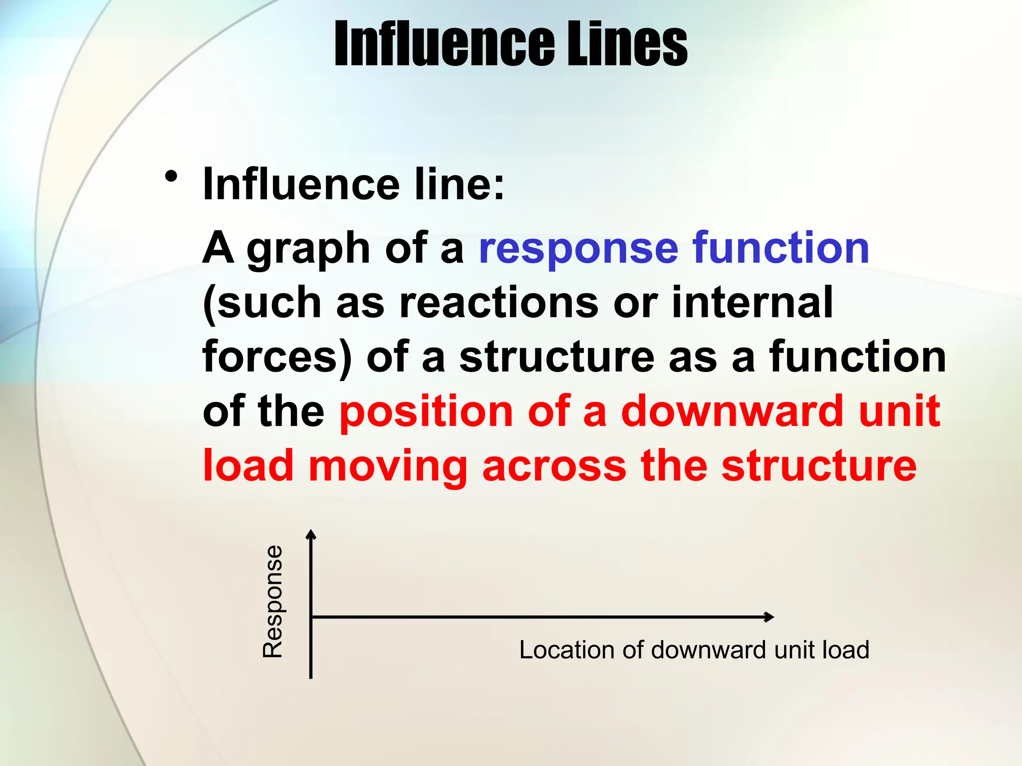
• Influenceline:
A graph of a response function
(such as reactions or internal
forces) of a structure as a function
of the position of a downward unit
load moving across the structure
Response
Location of downward unit load
Influence Lines
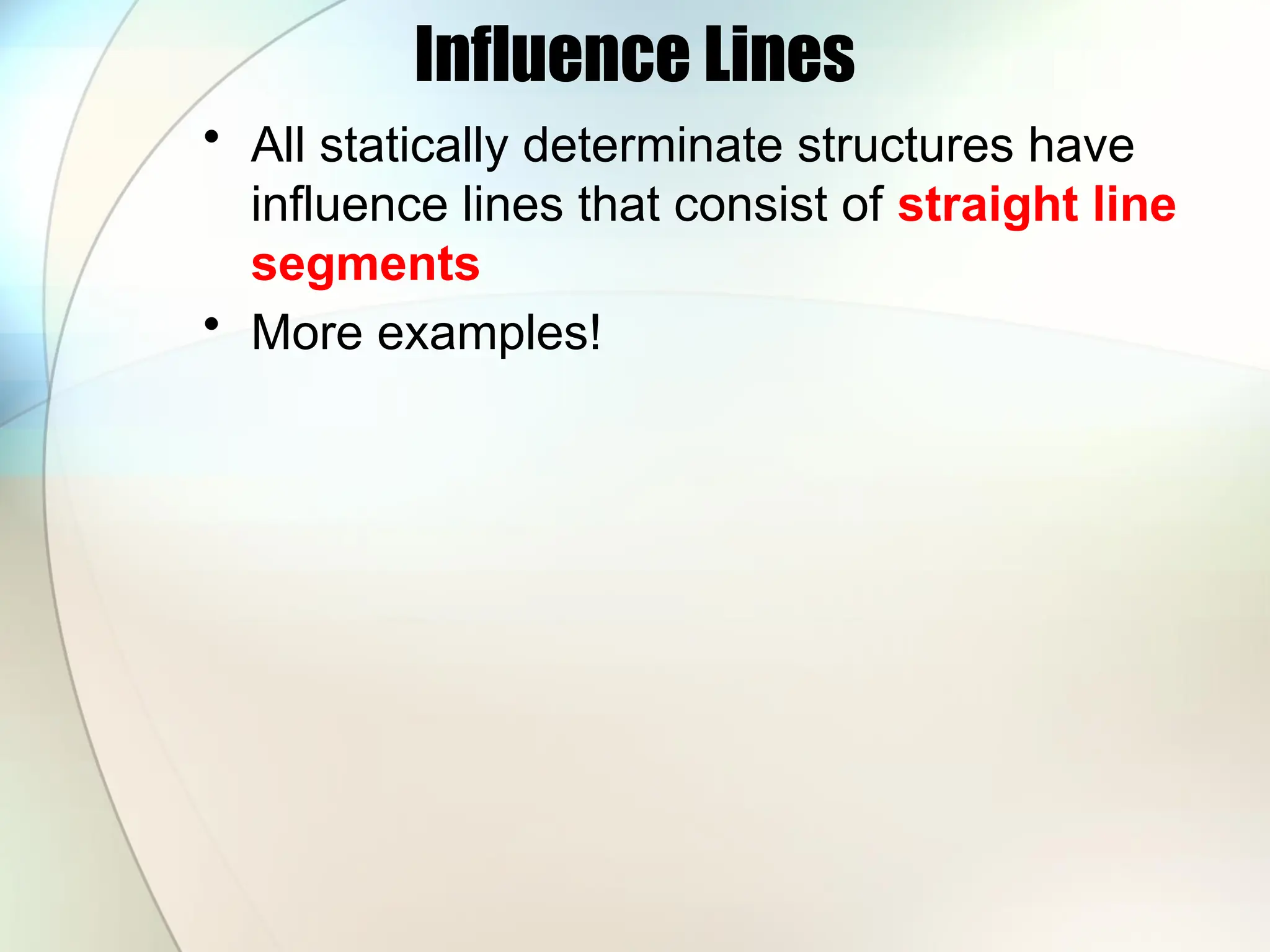
• Allstatically determinate structures have
influence lines that consist of straight line
segments
• More examples!
14.
Müller Breslau Principle
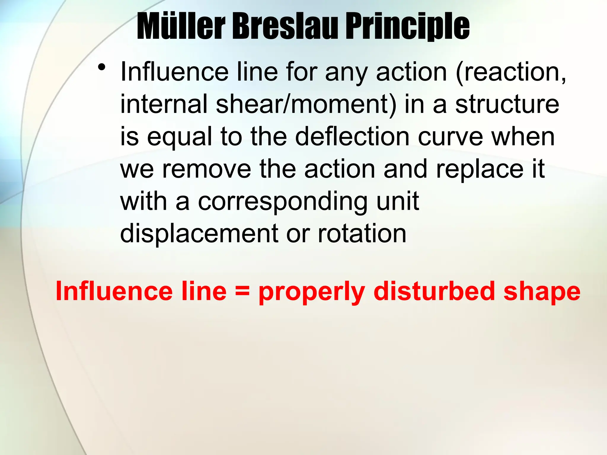
•Influence line for any action (reaction,
internal shear/moment) in a structure
is equal to the deflection curve when
we remove the action and replace it
with a corresponding unit
displacement or rotation
Influence line = properly disturbed shape
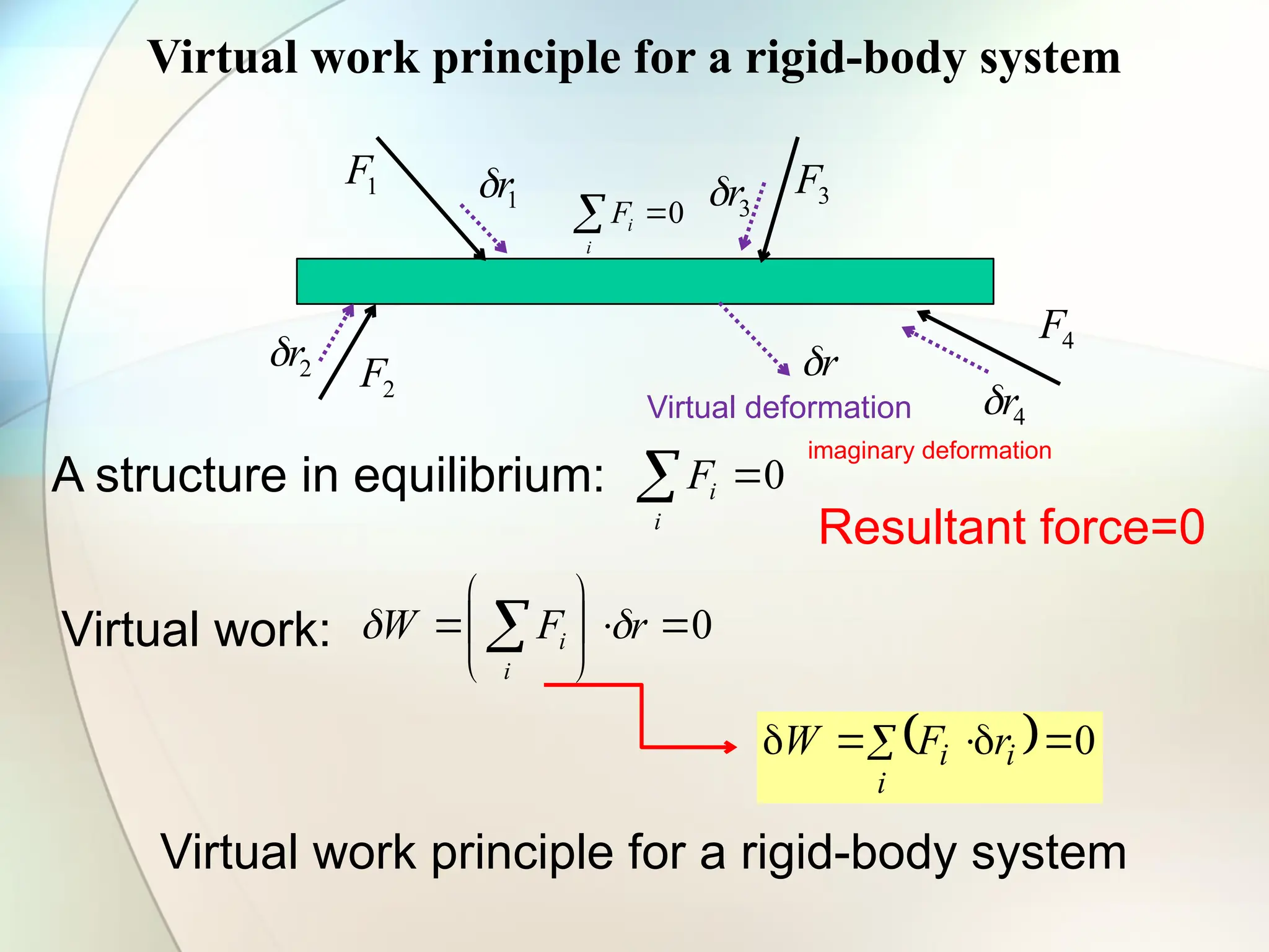
Virtual work principlefor a rigid-body system
A structure in equilibrium: 0
i
i
F
1
F
2
F
3
F
4
F
Resultant force=0
4
r
2
r
3
r
1
r
r
Virtual deformation
Virtual work: 0
r
F
W
i
i
0
i
i
i r
F
W
Virtual work principle for a rigid-body system
imaginary deformation
0
i
i
F
17.
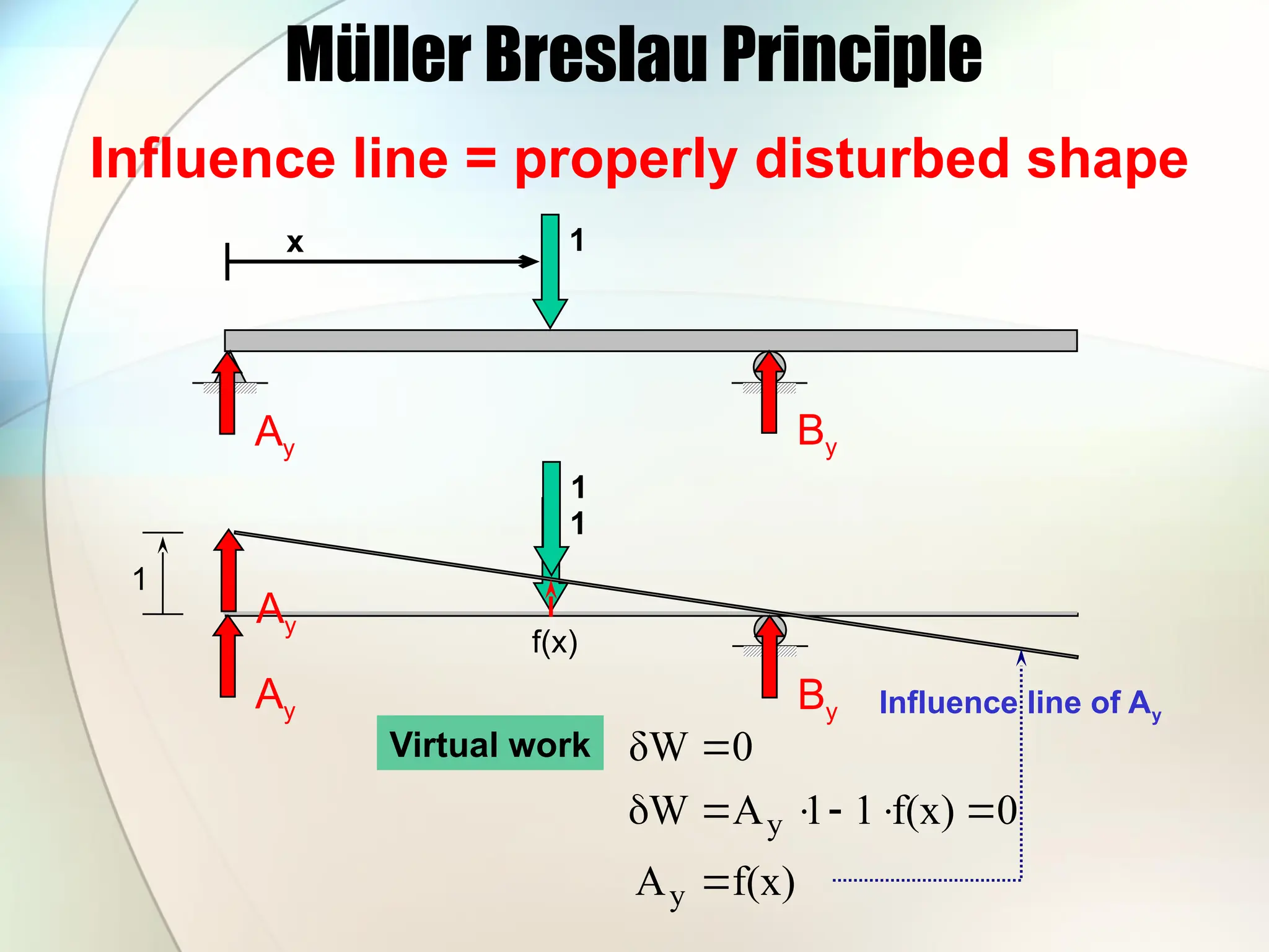
Müller Breslau Principle
x1
Influence line = properly disturbed shape
Ay
1
Ay
1
Ay
1
f(x)
f(x)
A
0
f(x)
1
1
A
W
0
δW
y
y
Influence line of Ay
Virtual work
By
By
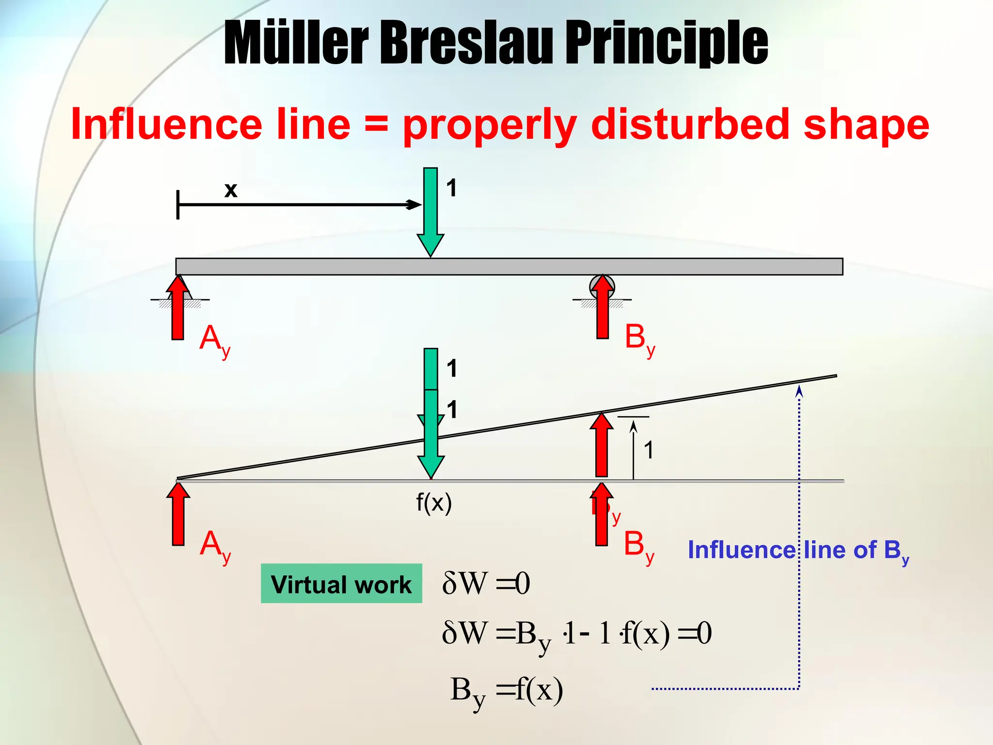
18.
Müller Breslau Principle
x1
Influence line = properly disturbed shape
Ay
1
By
1
f(x)
Virtual work
f(x)
B
0
f(x)
1
1
B
W
0
δW
y
y
Influence line of By
By
Ay
1
By
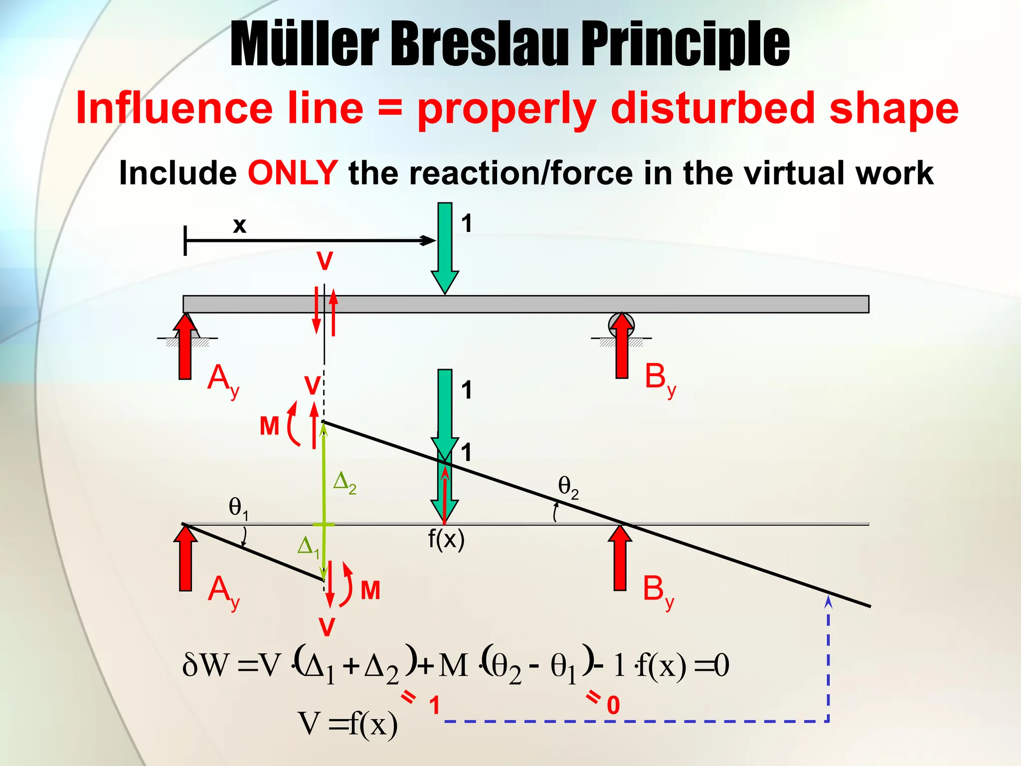
19.
Müller Breslau Principle
Influenceline = properly disturbed shape
x 1
Ay By
Ay
1
By
f(x)
1
V
M
V
V
M
D1
D2
q1
q2
0
f(x)
1
M
V
W 1
2
2
1
Include ONLY the reaction/force in the virtual work
=
1
=
0
f(x)
V
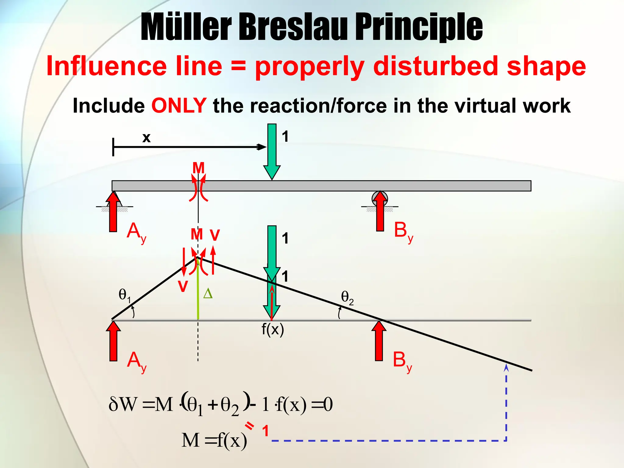
20.
Müller Breslau Principle
Influenceline = properly disturbed shape
x 1
Ay By
Ay
1
By
f(x)
1
D
q1 q2
0
f(x)
1
M
W 2
1
Include ONLY the reaction/force in the virtual work
=
1
f(x)
M
M
V
M
V
21.
Müller Breslau Principle
Influenceline = properly disturbed shape
Deflect the structure such that only the force
which influence line that you are looking for
and the downward unit force contribute to the
virtual work due to the imaginary deflection.
All other forces that act on the virtually
deflected structure should not contribute to the
virtual work.
22.
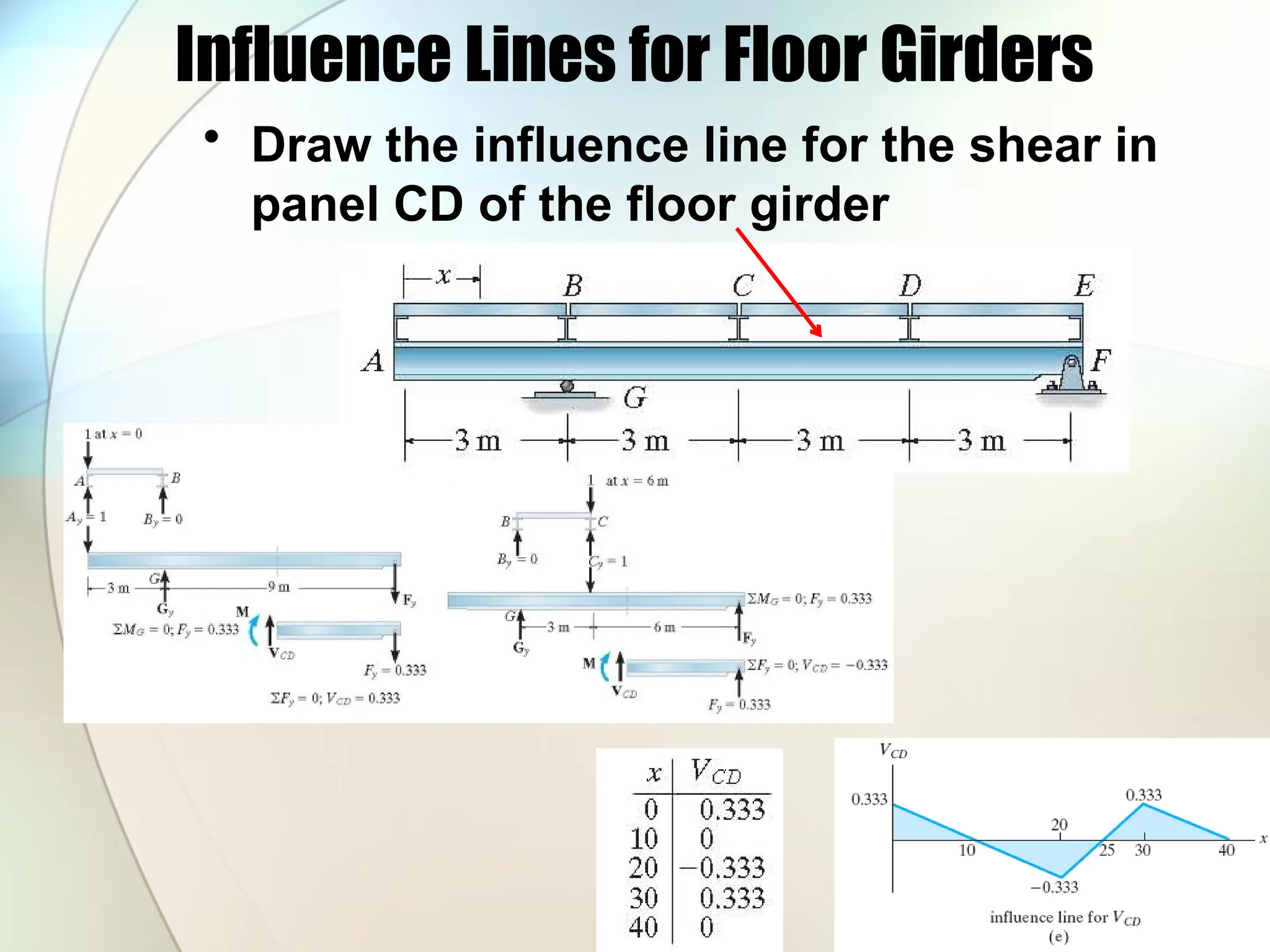
Influence Lines forFloor Girders
• Draw the influence line for the shear in
panel CD of the floor girder
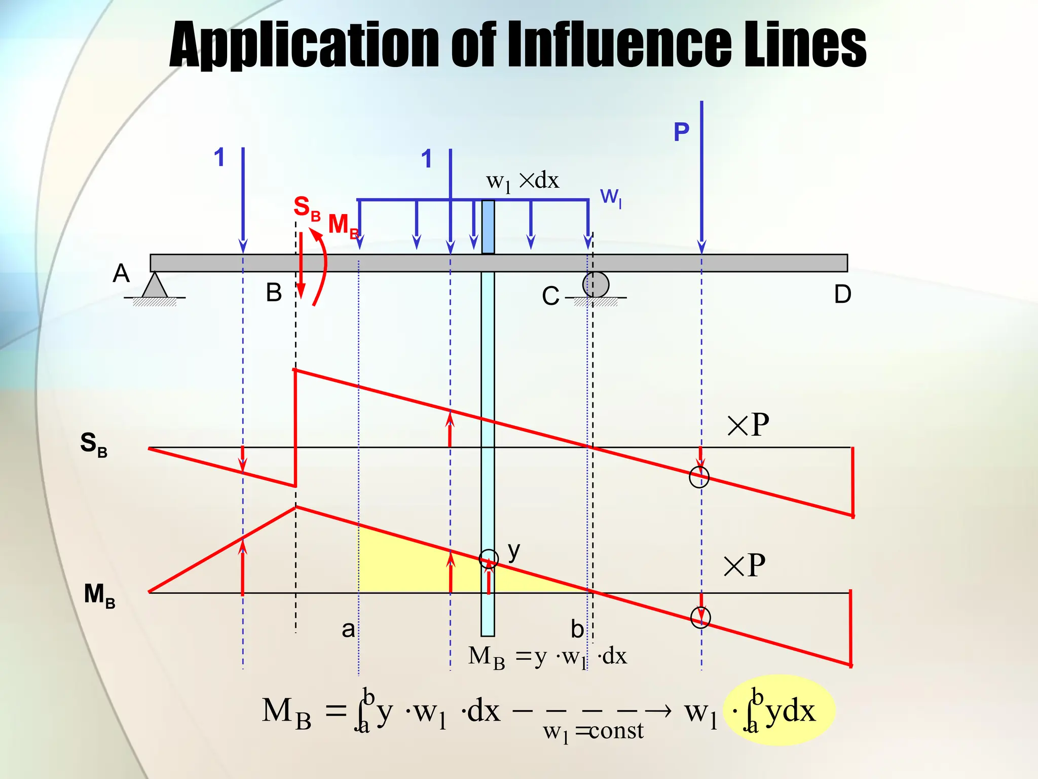
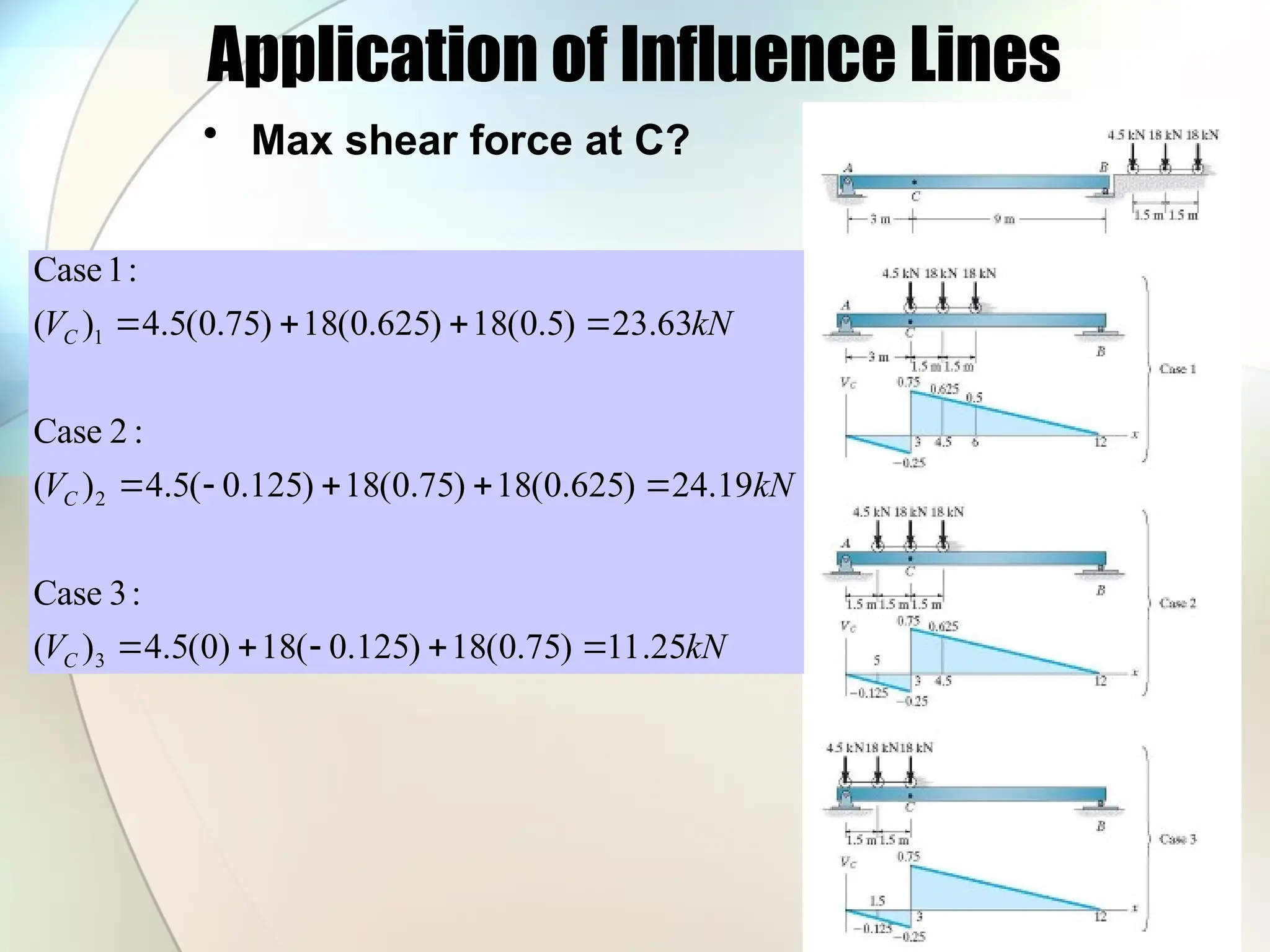
Application of InfluenceLines
A
B C D
SB
MB
1 1
P
P
P
SB
MB
wl
dx
wl
dx
w
y
M l
B
a b
b
a
l
const
w
b
a l
B ydx
w
dx
w
y
M
l
y
27.
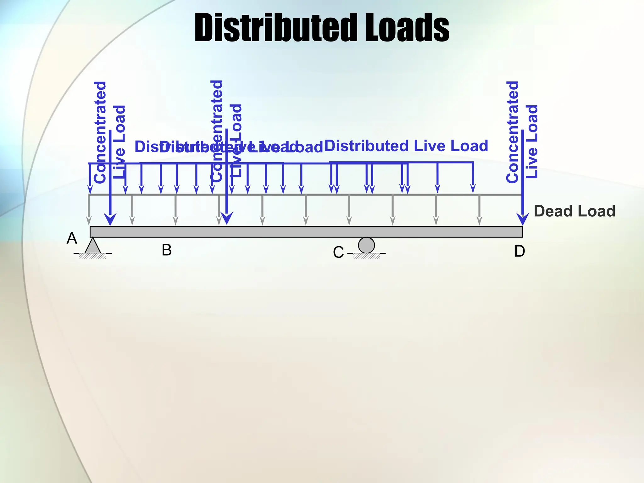
Distributed Loads
A
B CD
Dead Load
Concentrated
Live
Load
Concentrated
Live
Load
Concentrated
Live
Load
Distributed Live Load
Distributed Live LoadDistributed Live Load
28.
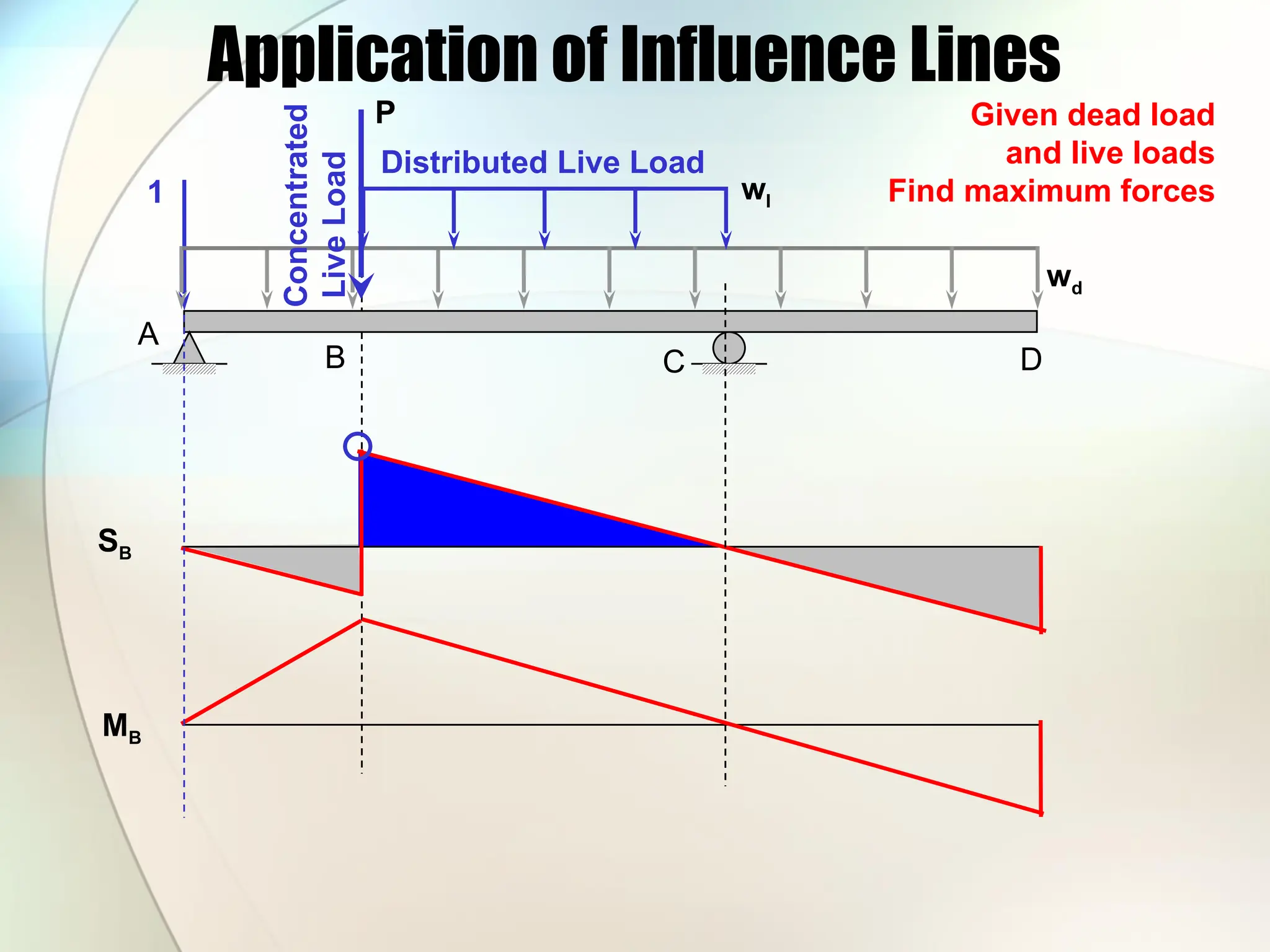
Application of InfluenceLines
A
B C D
SB
MB
1
Given dead load
and live loads
Find maximum forces
wd
Distributed Live Load
wl
Concentrated
Live
Load
P