▪ Seen techniquesfor analyzing the forces (Bending moment, shear and
axial forces) and deflection when the load acting on the structure is
always remain same.
▪ Such loads are termed as dead loads i.e. the magnitude of load do not
change position.
▪ But if a structure is subjected to live load (change position in life time
e.g. weight of person and furniture, vehicle movement across bridge,
EOT crane running over a gantry girder etc.) the forces and
displacement at various position of the structure be obtained
conveniently by using the concept of influence line diagram.
✓ When a moving load crosses the span, only at one location of load a
particular quantity (Bending moment, shear forces, deflection) become
severe.
✓ Interest is to know the maximum value of the specific quantity (say
BM) in the beam i.e. to know for what position of the load the BM in
the beam will be maximum.
✓ Note that the position of the load for maximum BM and for any other
quantity (shear, axial force) will be different.
3.
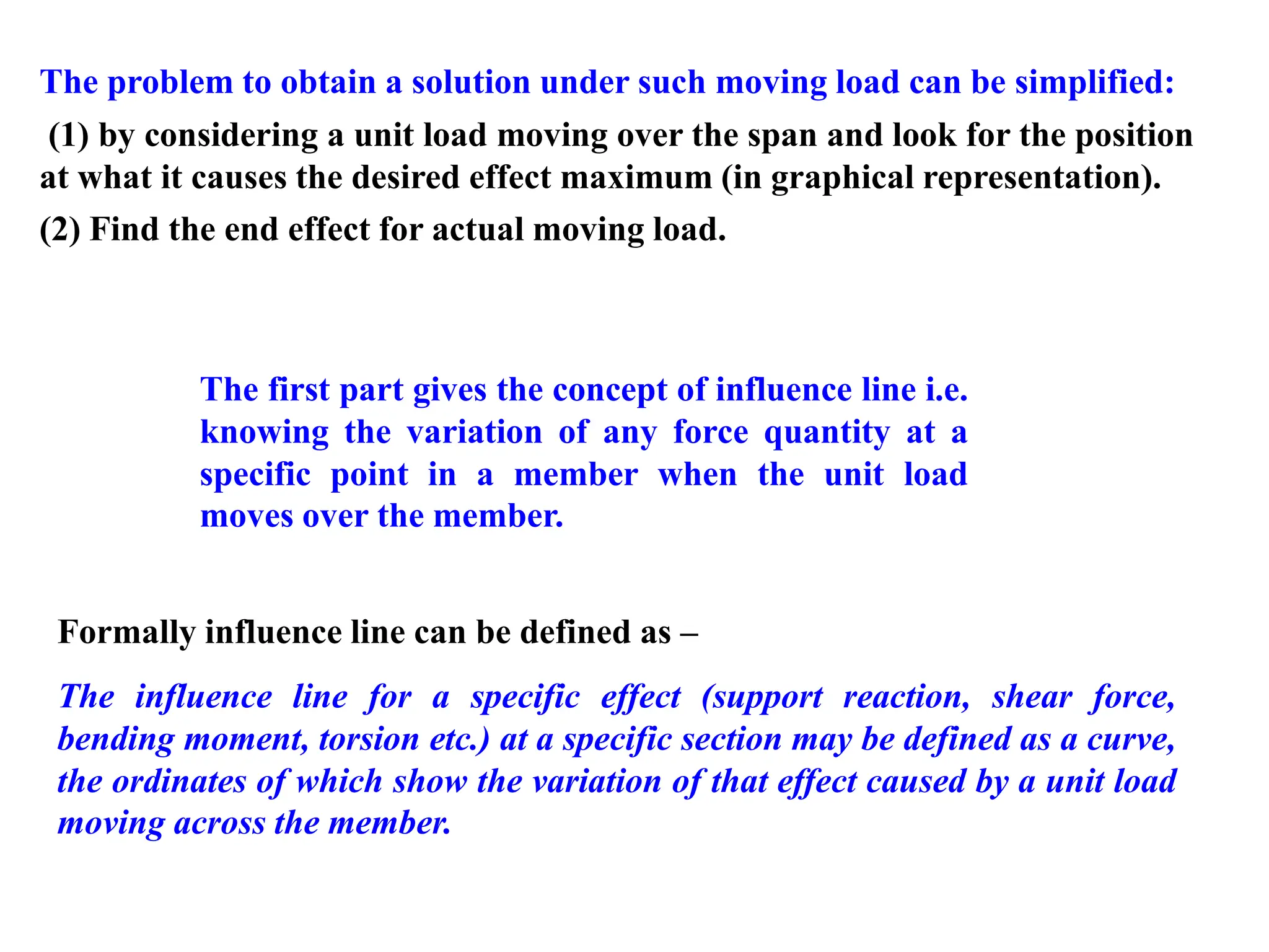
The problem toobtain a solution under such moving load can be simplified:
(1) by considering a unit load moving over the span and look for the position
at what it causes the desired effect maximum (in graphical representation).
(2) Find the end effect for actual moving load.
Formally influence line can be defined as –
The influence line for a specific effect (support reaction, shear force,
bending moment, torsion etc.) at a specific section may be defined as a curve,
the ordinates of which show the variation of that effect caused by a unit load
moving across the member.
The first part gives the concept of influence line i.e.
knowing the variation of any force quantity at a
specific point in a member when the unit load
moves over the member.
4.
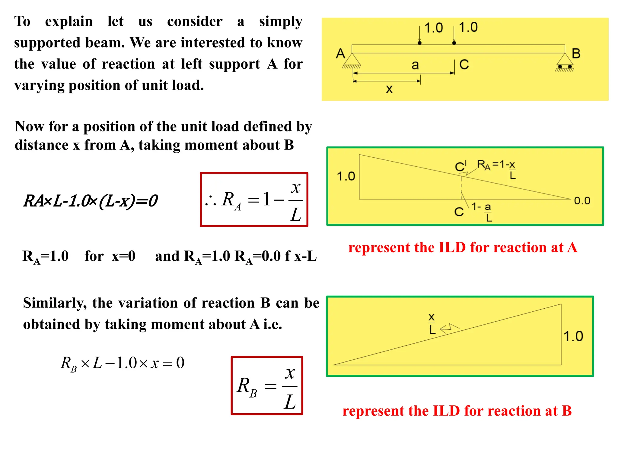
To explain letus consider a simply
supported beam. We are interested to know
the value of reaction at left support A for
varying position of unit load.
Now for a position of the unit load defined by
distance x from A, taking moment about B
RA×L-1.0×(L-x)=0 1
A
x
R
L
= −
RA=1.0 for x=0 and RA=1.0 RA=0.0 f x-L
Similarly, the variation of reaction B can be
obtained by taking moment about A i.e.
1.0 0
B
R L x
− =
B
x
R
L
=
represent the ILD for reaction at A
represent the ILD for reaction at B
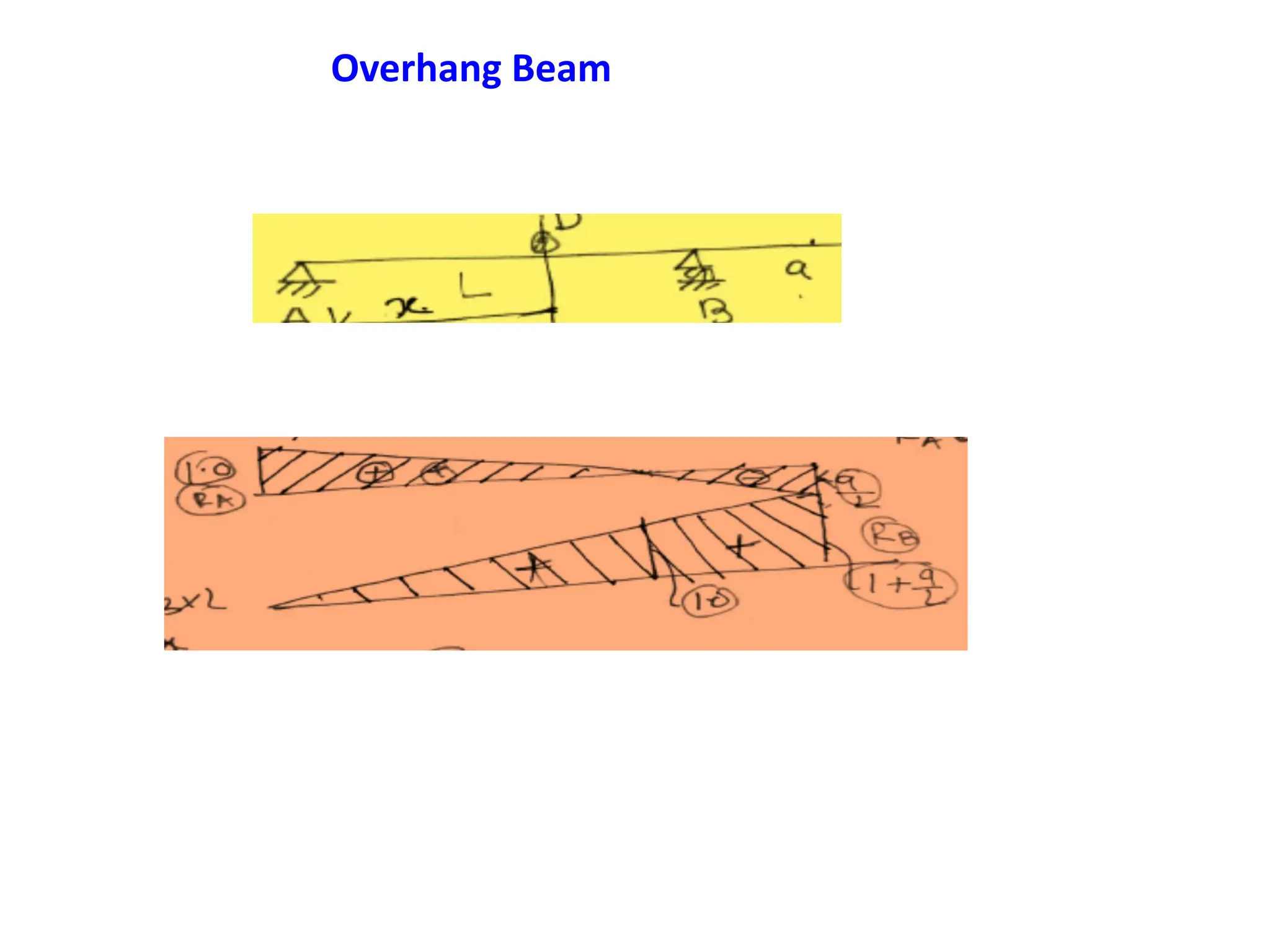
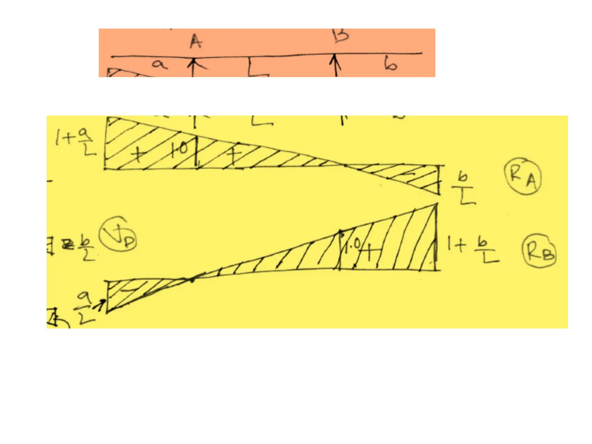
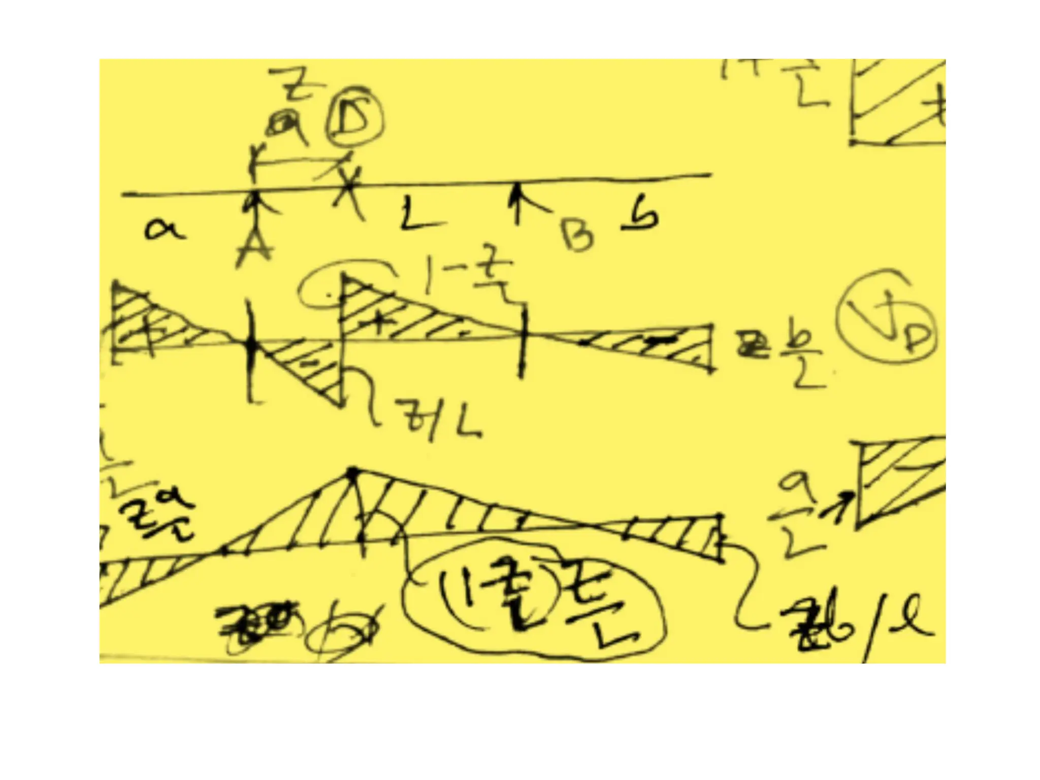
5.
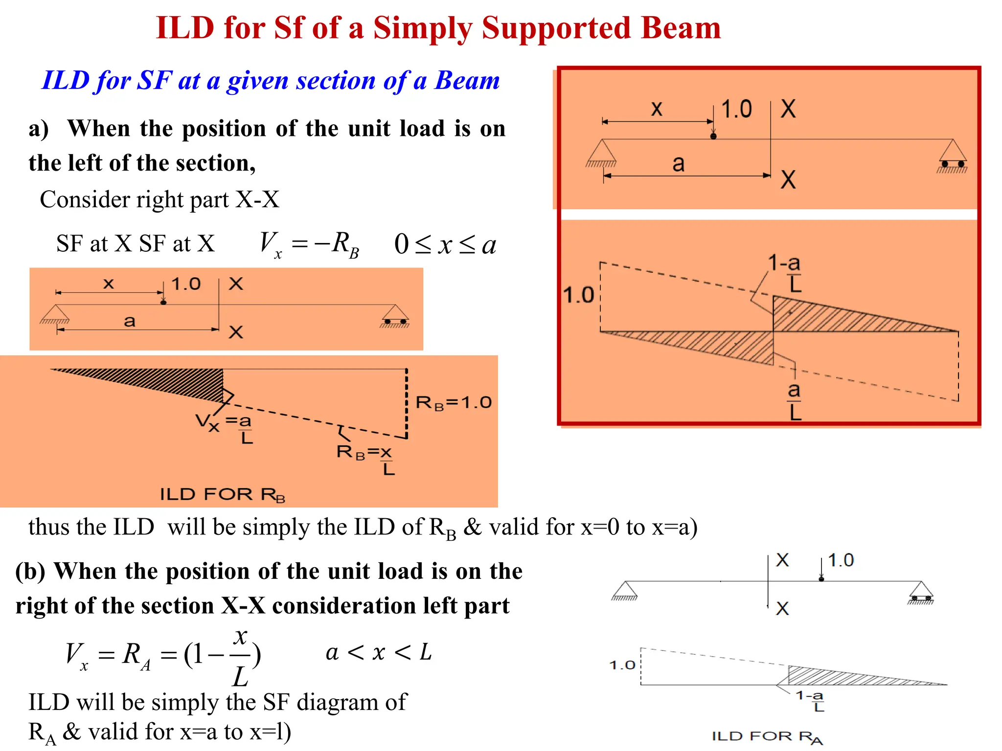
ILD for Sfof a Simply Supported Beam
ILD for SF at a given section of a Beam
a) When the position of the unit load is on
the left of the section,
SF at X SF at X
Consider right part X-X
x B
V R
= − 0 x a
thus the ILD will be simply the ILD of RB & valid for x=0 to x=a)
(b) When the position of the unit load is on the
right of the section X-X consideration left part
(1 )
x A
x
V R
L
= = − 𝑎 < 𝑥 < 𝐿
ILD will be simply the SF diagram of
RA & valid for x=a to x=l)
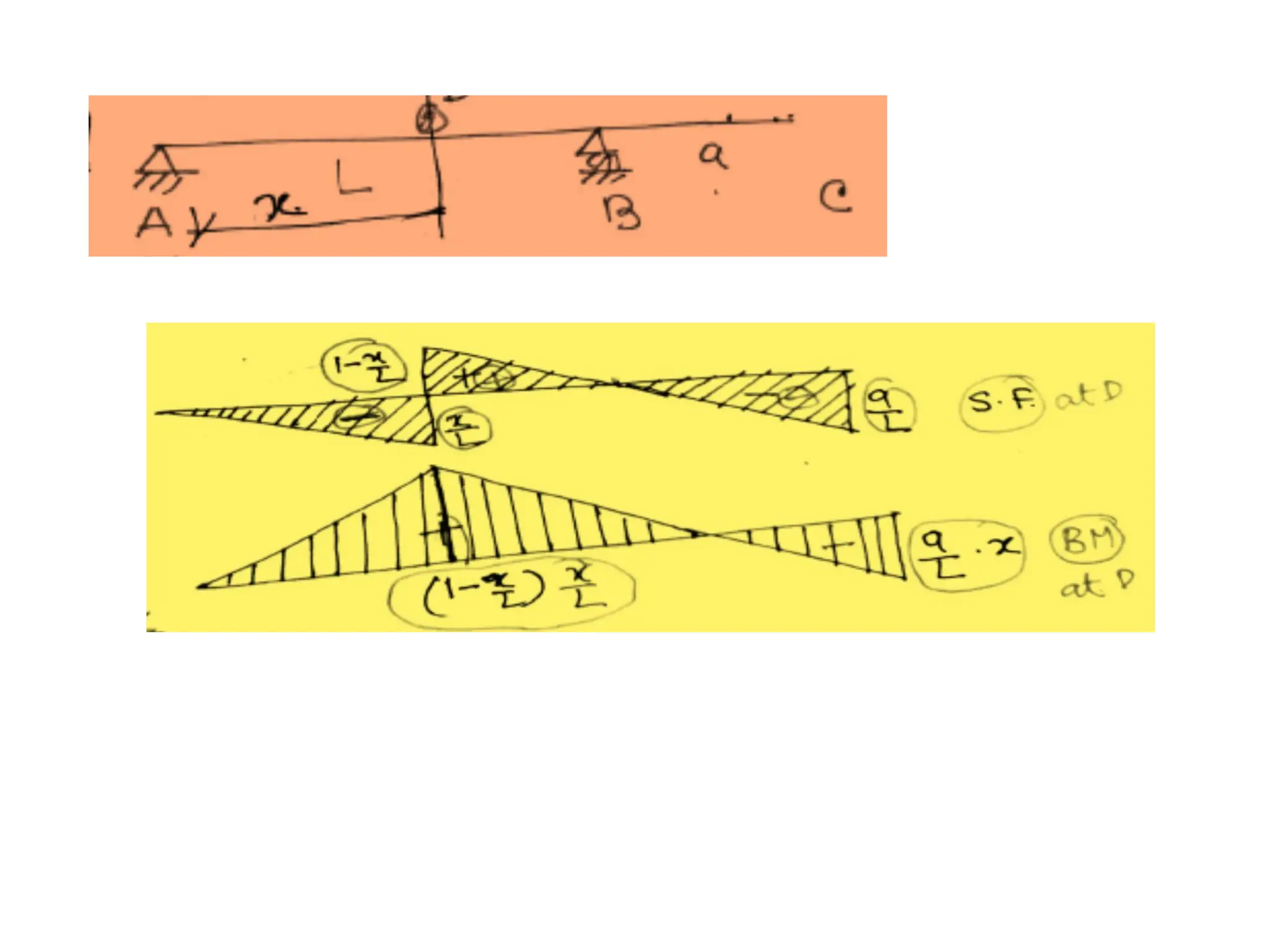
6.
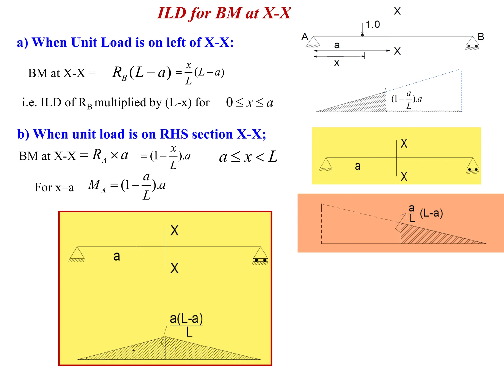
ILD for BMat X-X
a) When Unit Load is on left of X-X:
BM at X-X = ( )
B
R L a
− ( )
x
L a
L
= −
i.e. ILD of RB multiplied by (L-x) for 0 x a
b) When unit load is on RHS section X-X;
BM at X-X A
R a
= (1 ).
x
a
L
= − a x L
(1 ).
A
a
M a
L
= −
For x=a
(1 ).
a
a
L
−
7.
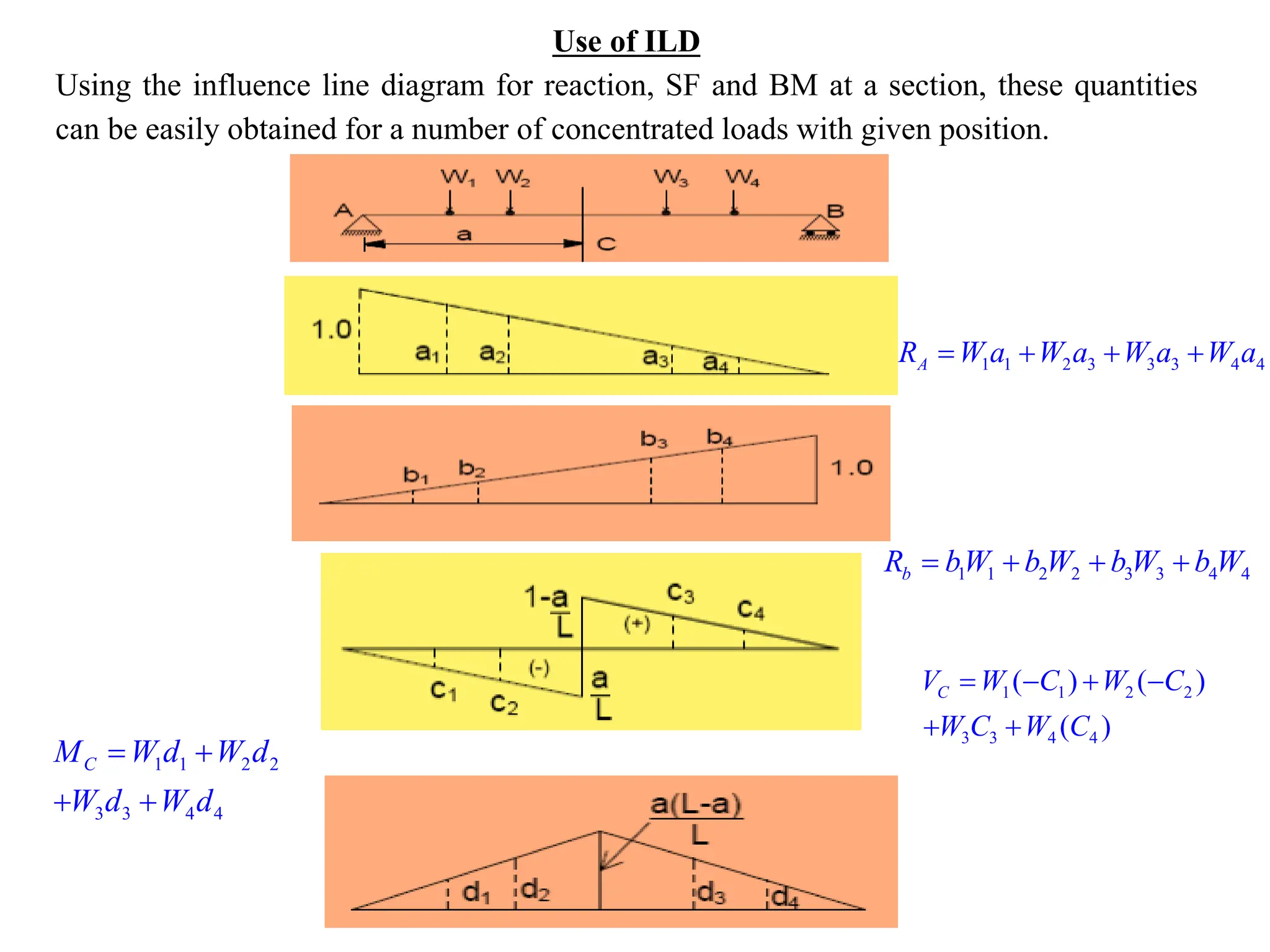
Use of ILD
Usingthe influence line diagram for reaction, SF and BM at a section, these quantities
can be easily obtained for a number of concentrated loads with given position.
1 1 2 3 3 3 4 4
A
R W a W a W a W a
= + + +
1 1 2 2 3 3 4 4
b
R bW b W b W b W
= + + +
1 1 2 2
3 3 4 4
( ) ( )
( )
= − + −
+ +
C
V W C W C
W C W C
1 1 2 2
3 3 4 4
= +
+ +
C
M W d W d
W d W d
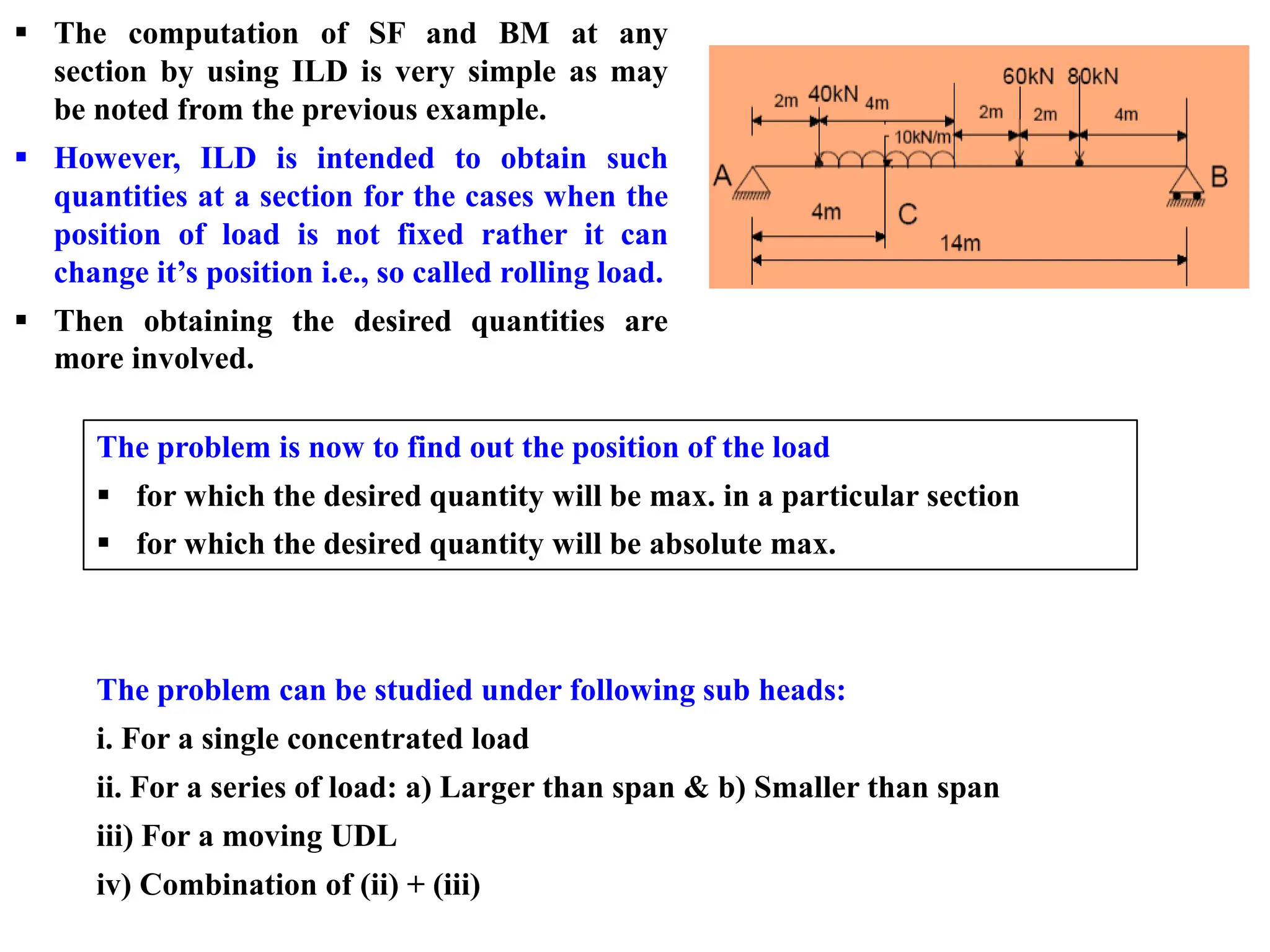
8.
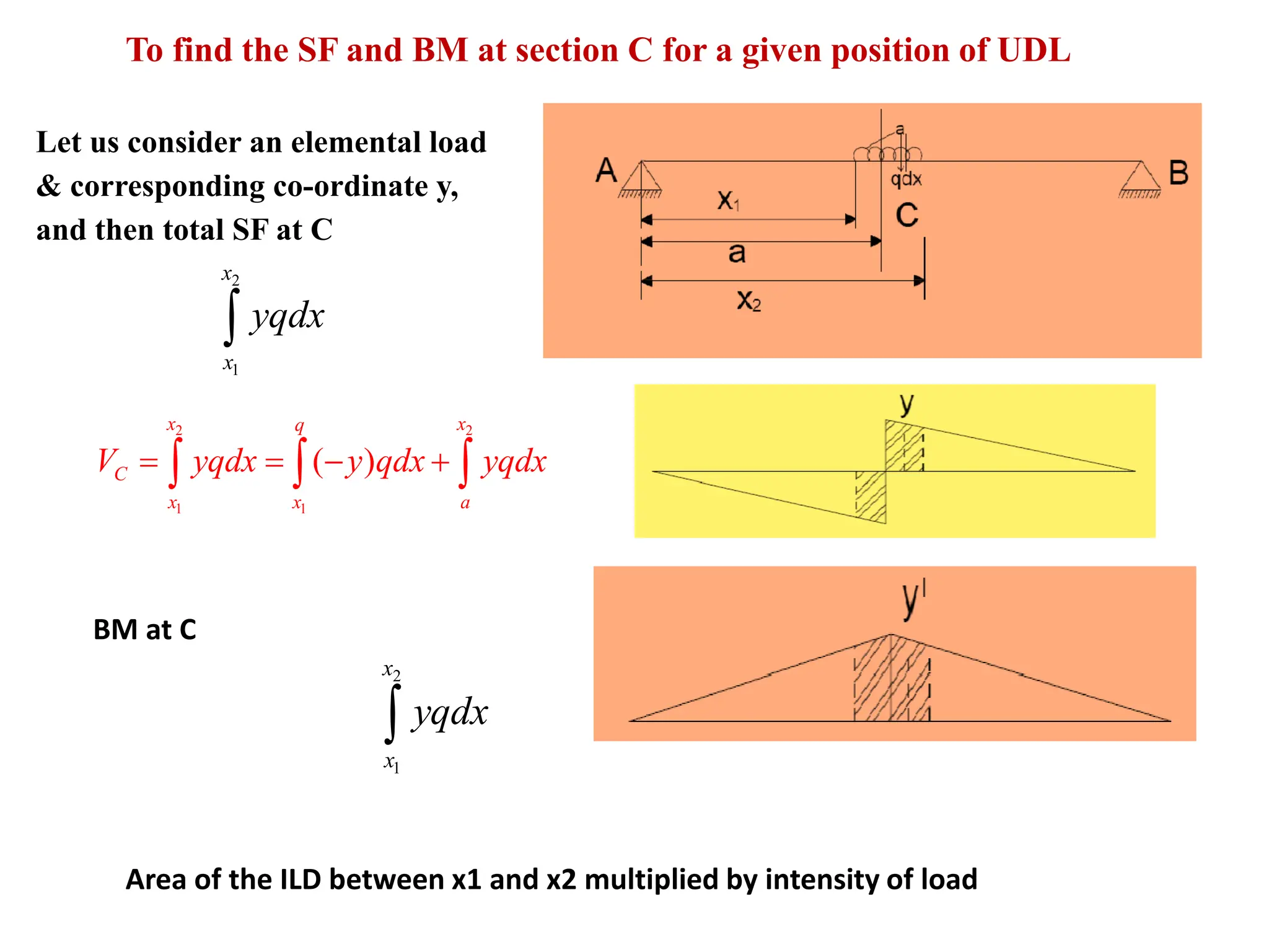
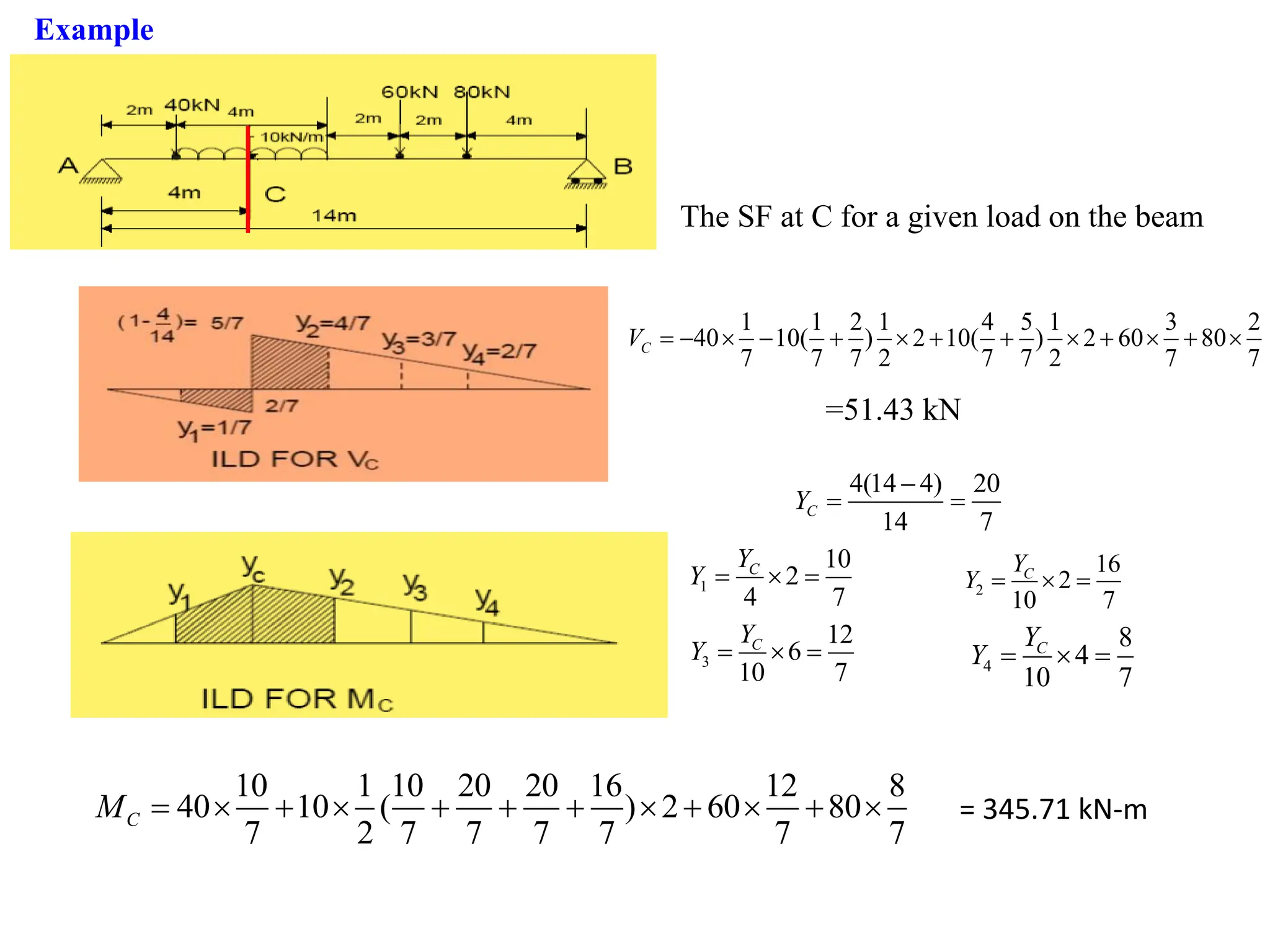
To find theSF and BM at section C for a given position of UDL
Let us consider an elemental load
& corresponding co-ordinate y,
and then total SF at C
2
1
x
x
yqdx
2 2
1 1
( )
= = − +
x x
q
C
x x a
V yqdx y qdx yqdx
2
1
x
x
yqdx
BM at C
Area of the ILD between x1 and x2 multiplied by intensity of load
9.
The SF atC for a given load on the beam
1 1 2 1 4 5 1 3 2
40 10( ) 2 10( ) 2 60 80
7 7 7 2 7 7 2 7 7
= − − + + + + +
C
V
=51.43 kN
4(14 4) 20
14 7
C
Y
−
= =
1
10
2
4 7
C
Y
Y = = 2
16
2
10 7
C
Y
Y = =
3
12
6
10 7
C
Y
Y = = 4
8
4
10 7
C
Y
Y = =
10 1 10 20 20 16 12 8
40 10 ( ) 2 60 80
7 2 7 7 7 7 7 7
C
M = + + + + + + = 345.71 kN-m
Example
10.
▪ The computationof SF and BM at any
section by using ILD is very simple as may
be noted from the previous example.
▪ However, ILD is intended to obtain such
quantities at a section for the cases when the
position of load is not fixed rather it can
change it’s position i.e., so called rolling load.
▪ Then obtaining the desired quantities are
more involved.
The problem is now to find out the position of the load
▪ for which the desired quantity will be max. in a particular section
▪ for which the desired quantity will be absolute max.
The problem can be studied under following sub heads:
i. For a single concentrated load
ii. For a series of load: a) Larger than span & b) Smaller than span
iii) For a moving UDL
iv) Combination of (ii) + (iii)
11.
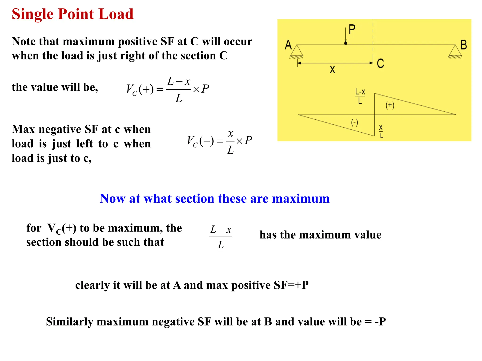
Single Point Load
Notethat maximum positive SF at C will occur
when the load is just right of the section C
( )
C
L x
V P
L
−
+ =
Max negative SF at c when
load is just left to c when
load is just to c,
( )
C
x
V P
L
− =
Now at what section these are maximum
L x
L
−
has the maximum value
clearly it will be at A and max positive SF=+P
Similarly maximum negative SF will be at B and value will be = -P
the value will be,
for VC(+) to be maximum, the
section should be such that
12.
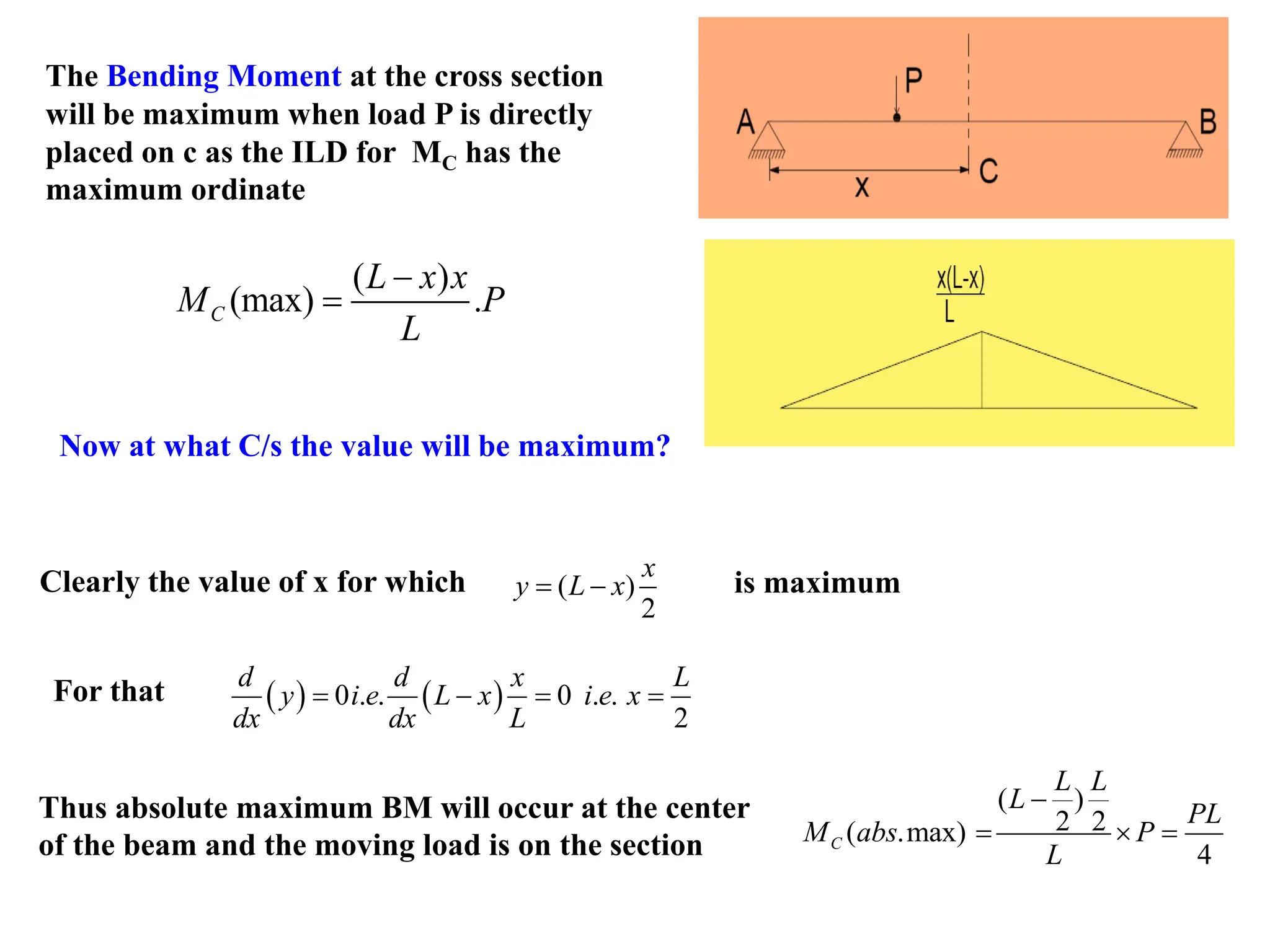
The Bending Momentat the cross section
will be maximum when load P is directly
placed on c as the ILD for MC has the
maximum ordinate
( )
(max) .
C
L x x
M P
L
−
=
Now at what C/s the value will be maximum?
Clearly the value of x for which ( )
2
x
y L x
= − is maximum
For that ( ) ( )
0 . .
2
. 0 .
d d x
y i e L x i e
dx d
L
x
x L
= =
− =
Thus absolute maximum BM will occur at the center
of the beam and the moving load is on the section
( )
2 2
( .max)
4
C
L L
L
PL
M abs P
L
−
= =
13.
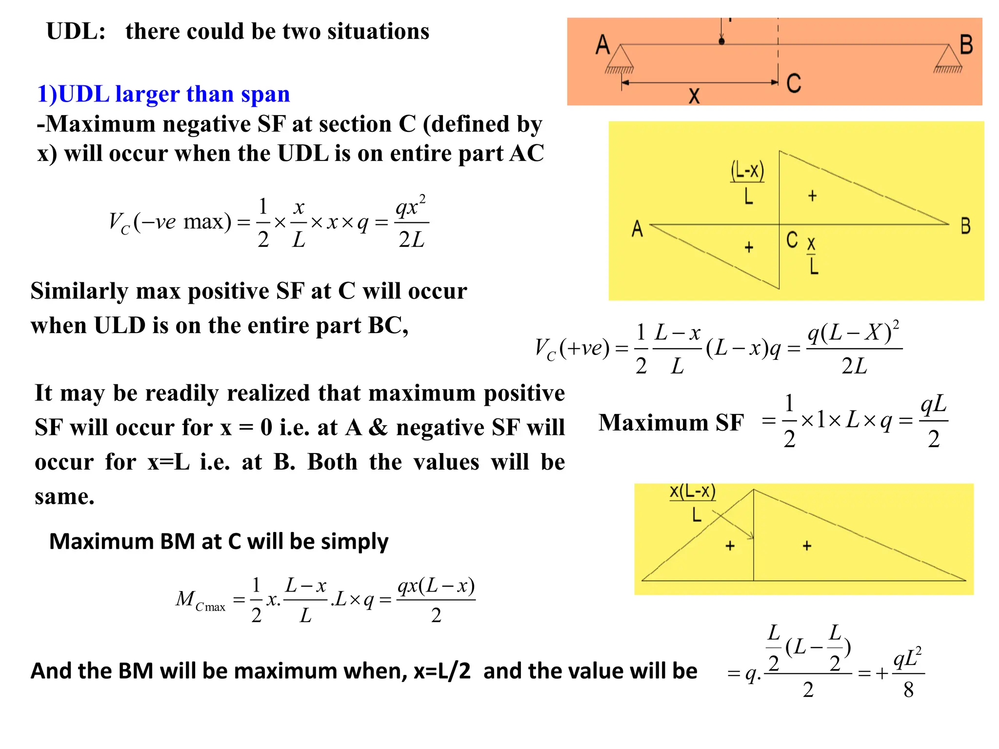
UDL: there couldbe two situations
1)UDL larger than span
-Maximum negative SF at section C (defined by
x) will occur when the UDL is on entire part AC
2
1
( max)
2 2
C
x qx
V ve x q
L L
− = =
Similarly max positive SF at C will occur
when ULD is on the entire part BC, 2
1 ( )
( ) ( )
2 2
C
L x q L X
V ve L x q
L L
− −
+ = − =
It may be readily realized that maximum positive
SF will occur for x = 0 i.e. at A & negative SF will
occur for x=L i.e. at B. Both the values will be
same.
1
1
2 2
qL
L q
= =
Maximum SF
Maximum BM at C will be simply
max
1 ( )
. .
2 2
C
L x qx L x
M x L q
L
− −
= =
And the BM will be maximum when, x=L/2
2
( )
2 2
.
2 8
L L
L
qL
q
−
= = +
and the value will be
14.
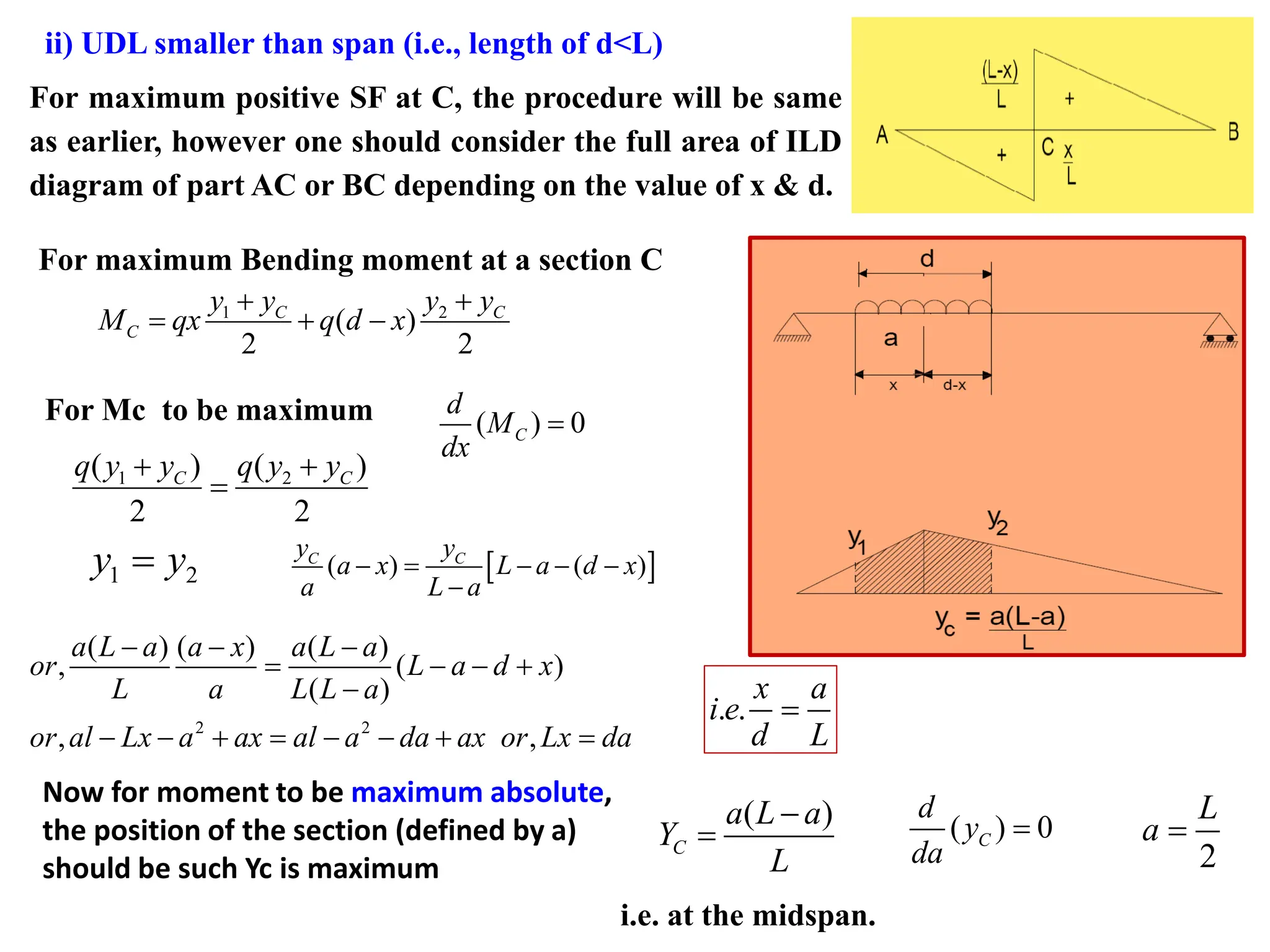
ii) UDL smallerthan span (i.e., length of d<L)
For maximum positive SF at C, the procedure will be same
as earlier, however one should consider the full area of ILD
diagram of part AC or BC depending on the value of x & d.
For maximum Bending moment at a section C
1 2
( )
2 2
C C
C
y y y y
M qx q d x
+ +
= + −
For Mc to be maximum ( ) 0
C
d
M
dx
=
1 2
( ) ( )
2 2
C C
q y y q y y
+ +
=
1 2
y y
=
( ) ( )
C C
y y
a x L a d x
a L a
− = − − −
−
2 2
( ) ( ) ( )
, ( )
( )
, ,
a L a a x a L a
or L a d x
L a L L a
or al Lx a ax al a da ax or Lx da
− − −
= − − +
−
− − + = − − + =
. .
x a
i e
d L
=
Now for moment to be maximum absolute,
the position of the section (defined by a)
should be such Yc is maximum
( )
C
a L a
Y
L
−
= ( ) 0
C
d
y
da
=
2
L
a =
i.e. at the midspan.
15.
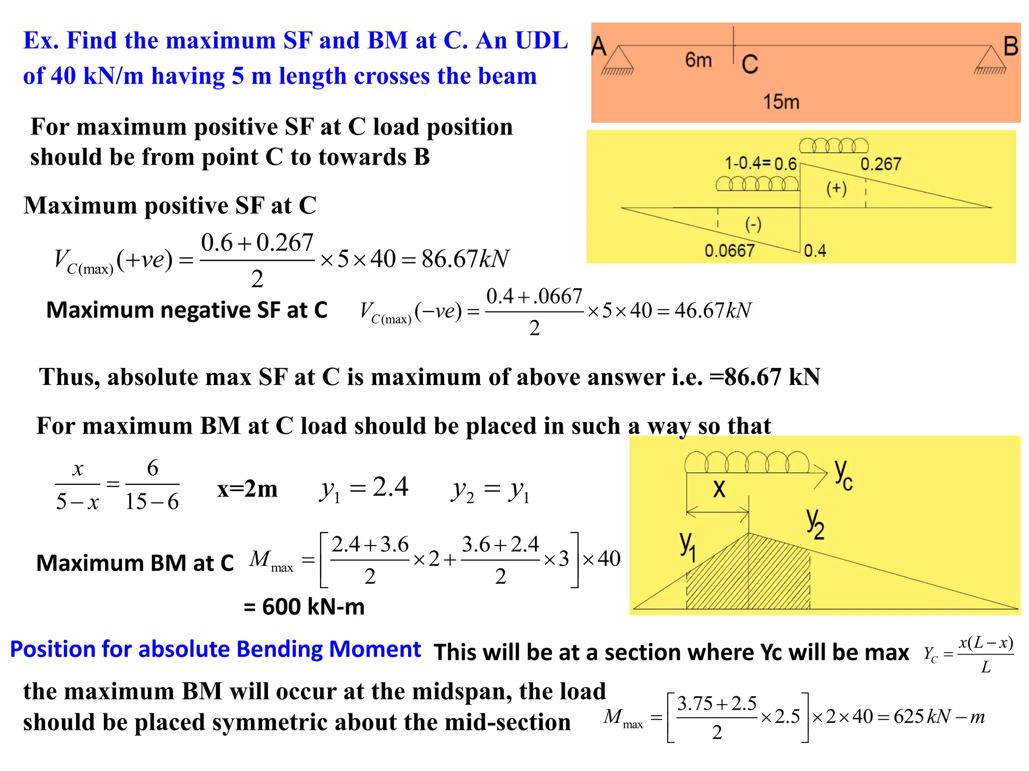
Ex. Find themaximum SF and BM at C. An UDL
of 40 kN/m having 5 m length crosses the beam
For maximum positive SF at C load position
should be from point C to towards B
Maximum positive SF at C
(max)
0.6 0.267
( ) 5 40 86.67
2
C
V ve kN
+
+ = =
(max)
0.4 .0667
( ) 5 40 46.67
2
C
V ve kN
+
− = =
Maximum negative SF at C
Thus, absolute max SF at C is maximum of above answer i.e. =86.67 kN
For maximum BM at C load should be placed in such a way so that
6
5 15 6
x
x
=
− −
x=2m 1 2 1
2.4
y y y
= =
max
2.4 3.6 3.6 2.4
2 3 40
2 2
M
+ +
= +
Maximum BM at C
= 600 kN-m
Position for absolute Bending Moment This will be at a section where Yc will be max ( )
C
x L x
Y
L
−
=
the maximum BM will occur at the midspan, the load
should be placed symmetric about the mid-section max
3.75 2.5
2.5 2 40 625
2
M kN m
+
= = −
16.
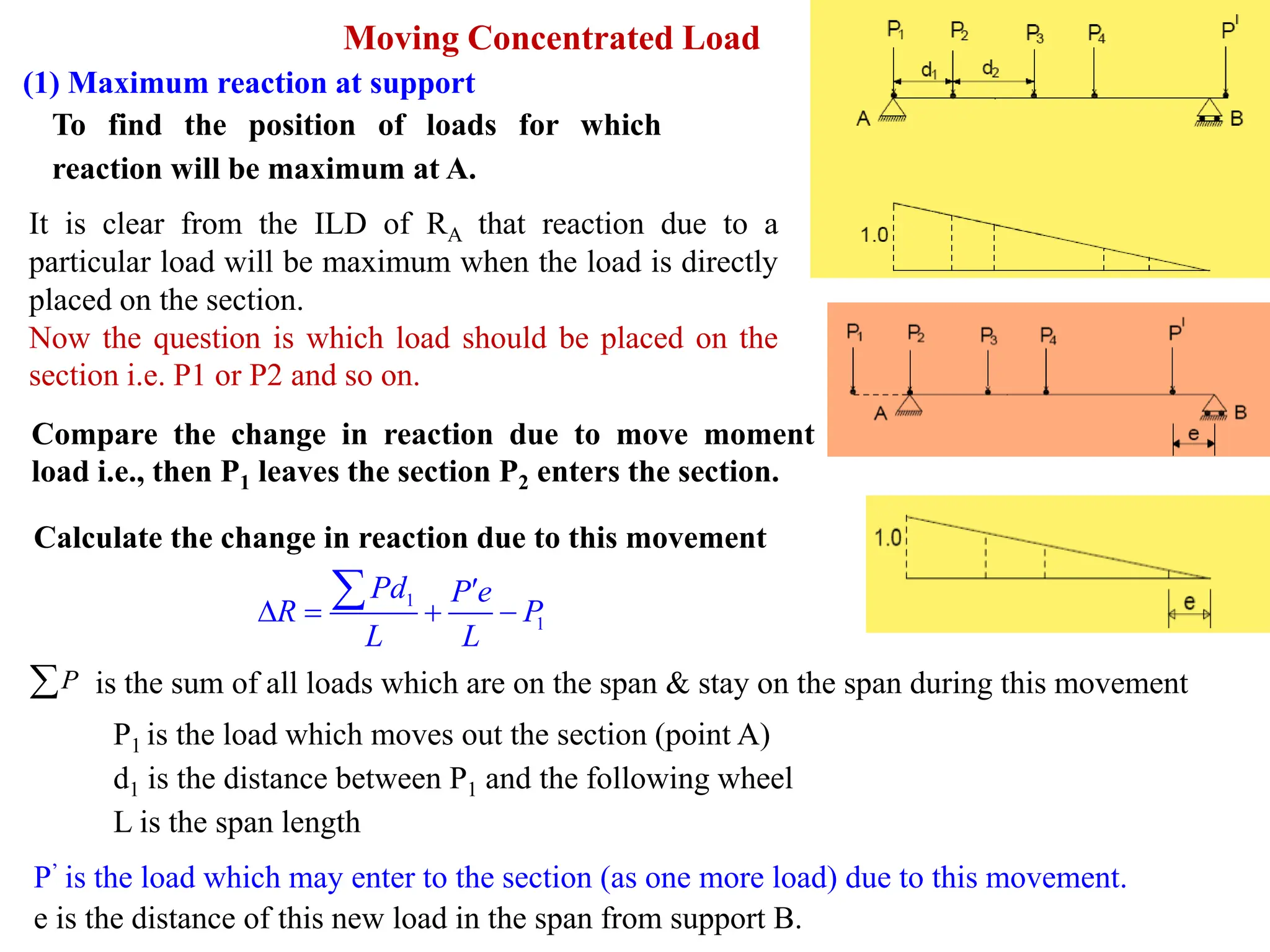
Moving Concentrated Load
(1)Maximum reaction at support
To find the position of loads for which
reaction will be maximum at A.
It is clear from the ILD of RA that reaction due to a
particular load will be maximum when the load is directly
placed on the section.
Now the question is which load should be placed on the
section i.e. P1 or P2 and so on.
Compare the change in reaction due to move moment
load i.e., then P1 leaves the section P2 enters the section.
Calculate the change in reaction due to this movement
1
1
Pd P e
R P
L L
= + −
P
is the sum of all loads which are on the span & stay on the span during this movement
P1 is the load which moves out the section (point A)
d1 is the distance between P1 and the following wheel
L is the span length
P’ is the load which may enter to the section (as one more load) due to this movement.
e is the distance of this new load in the span from support B.
17.
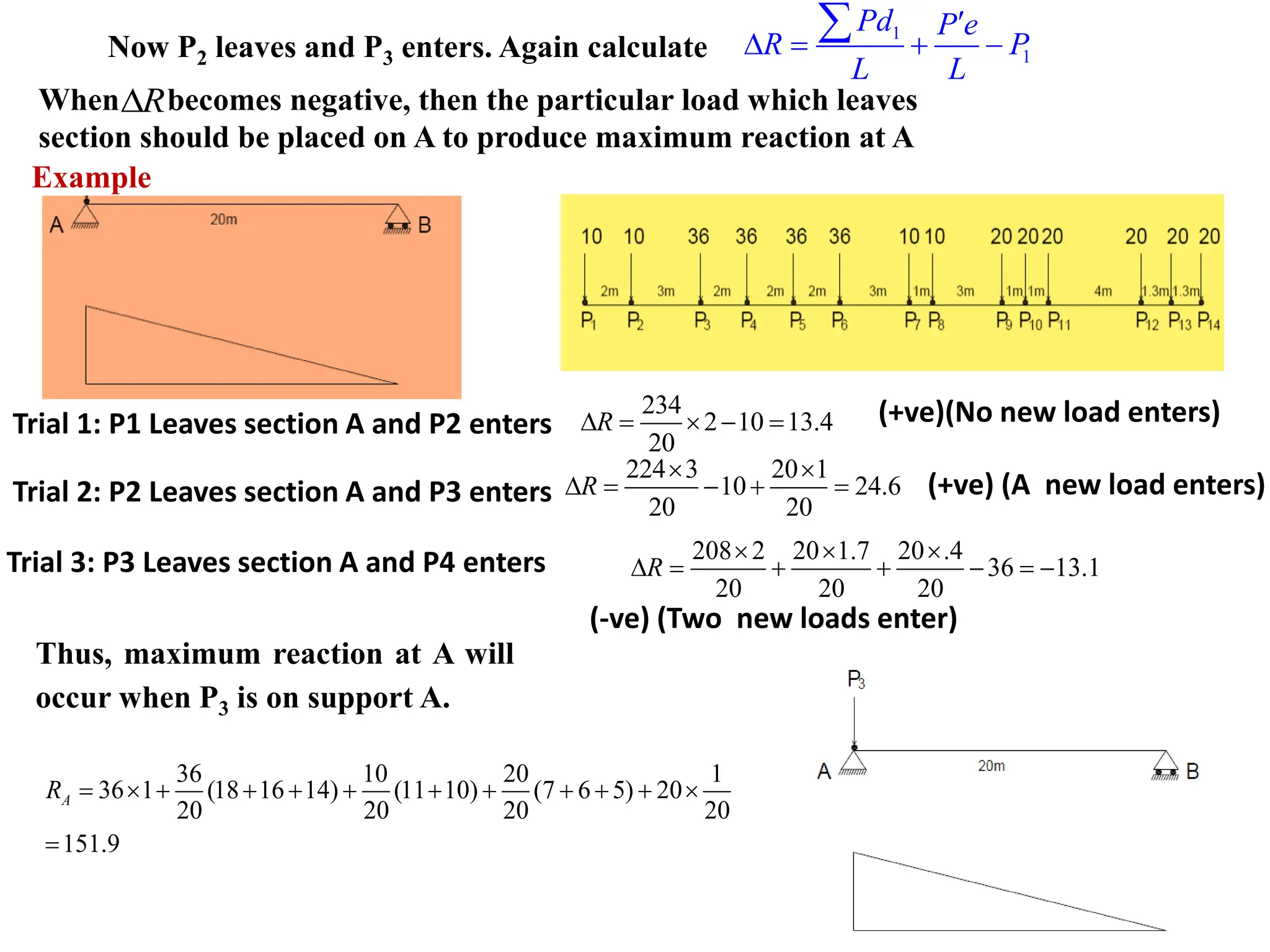
Now P2 leavesand P3 enters. Again calculate
When becomes negative, then the particular load which leaves
section should be placed on A to produce maximum reaction at A
Trial 1: P1 Leaves section A and P2 enters
234
2 10 13.4
20
R
= − =
Trial 2: P2 Leaves section A and P3 enters
224 3 20 1
10 24.6
20 20
R
= − + =
(+ve)(No new load enters)
(+ve) (A new load enters)
Trial 3: P3 Leaves section A and P4 enters 208 2 20 1.7 20 .4
36 13.1
20 20 20
R
= + + − = −
(-ve) (Two new loads enter)
Thus, maximum reaction at A will
occur when P3 is on support A.
36 10 20 1
36 1 (18 16 14) (11 10) (7 6 5) 20
20 20 20 20
151.9
A
R = + + + + + + + + +
=
Example
R
1
1
Pd P e
R P
L L
= + −
18.
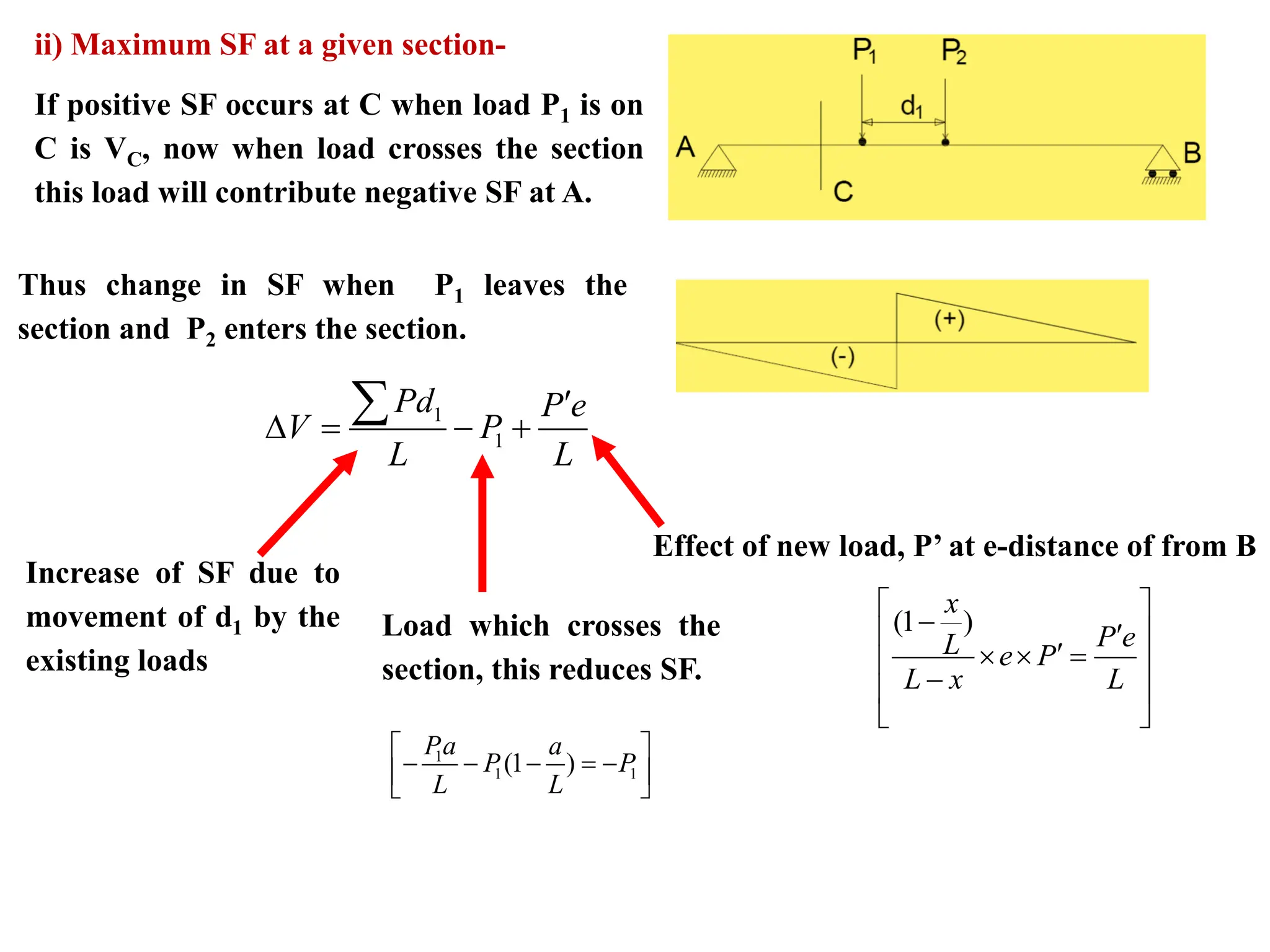
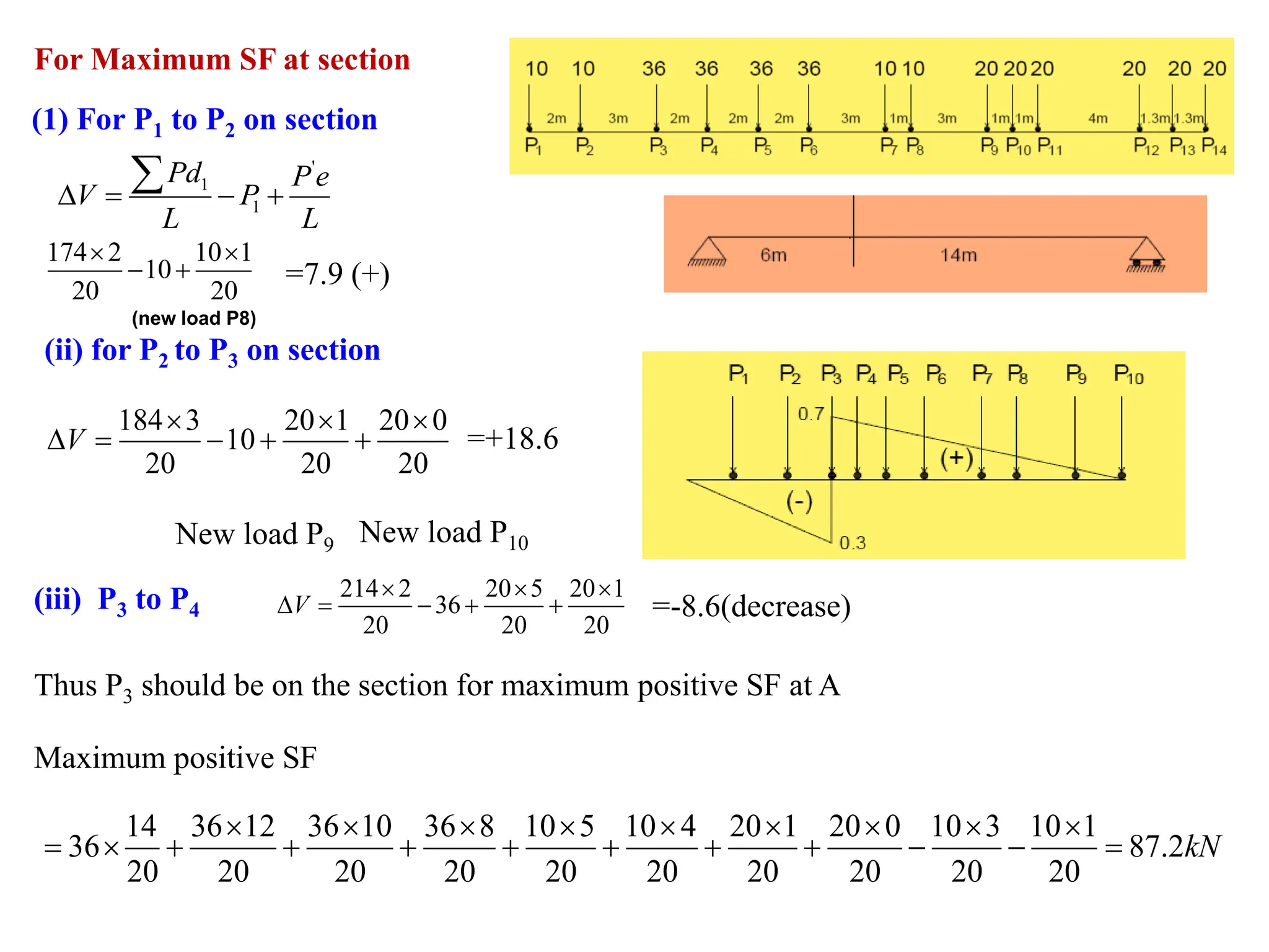
ii) Maximum SFat a given section-
If positive SF occurs at C when load P1 is on
C is VC, now when load crosses the section
this load will contribute negative SF at A.
Thus change in SF when P1 leaves the
section and P2 enters the section.
1
1
Pd P e
V P
L L
= − +
Effect of new load, P’ at e-distance of from B
(1 )
x
P e
L e P
L x L
−
=
−
Increase of SF due to
movement of d1 by the
existing loads
Load which crosses the
section, this reduces SF.
1
1 1
(1 )
Pa a
P P
L L
− − − = −
19.
(1) For P1to P2 on section
'
1
1
Pd Pe
V P
L L
= − +
174 2 10 1
10
20 20
− +
(new load P8)
=7.9 (+)
(ii) for P2 to P3 on section
184 3 20 1 20 0
10
20 20 20
= − + +
V
New load P9 New load P10
=+18.6
(iii) P3 to P4
214 2 20 5 20 1
36
20 20 20
= − + +
V =-8.6(decrease)
Thus P3 should be on the section for maximum positive SF at A
14 36 12 36 10 36 8 10 5 10 4 20 1 20 0 10 3 10 1
36 87.2
20 20 20 20 20 20 20 20 20 20
kN
= + + + + + + + − − =
Maximum positive SF
For Maximum SF at section
20.
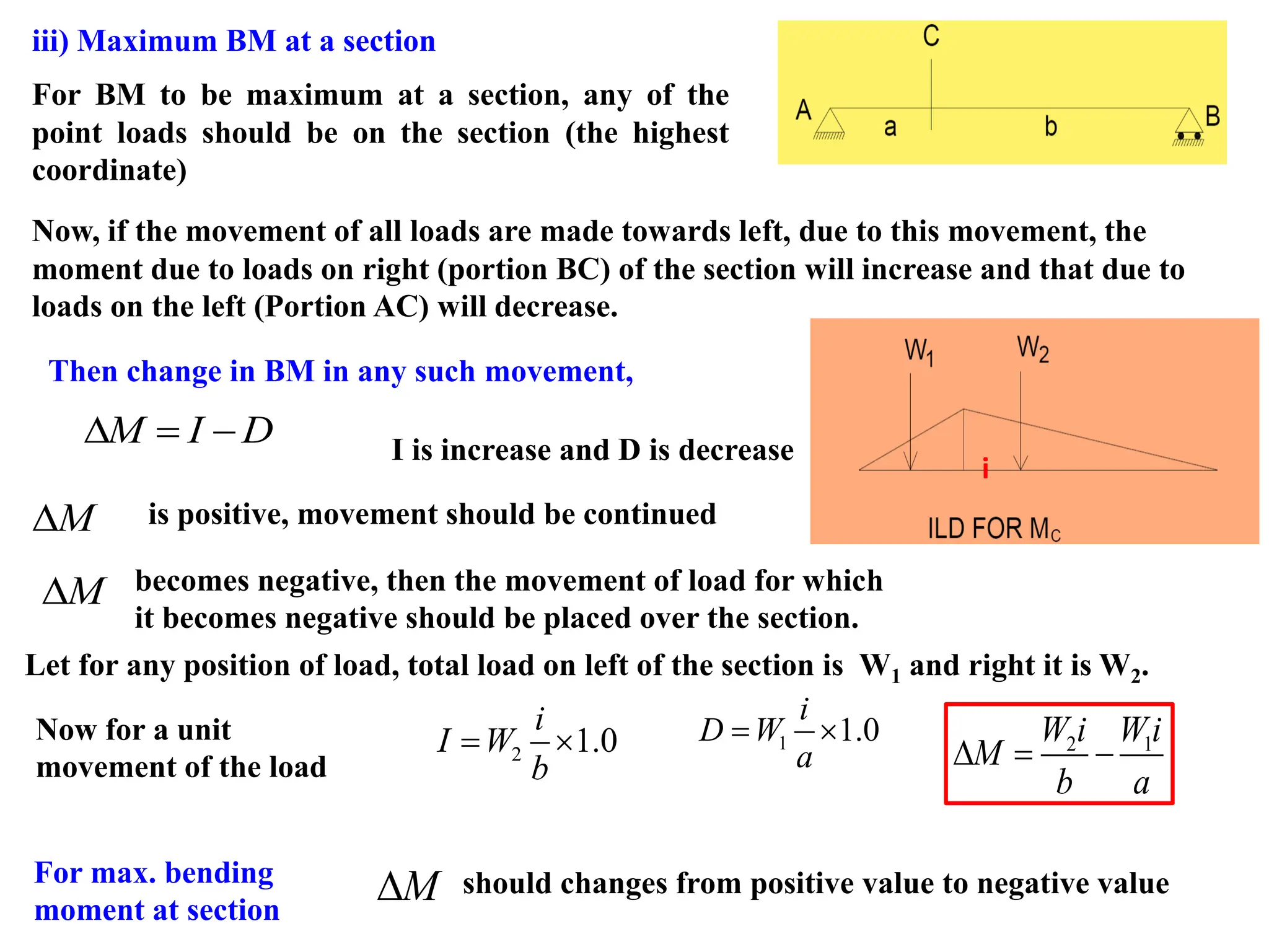
iii) Maximum BMat a section
For BM to be maximum at a section, any of the
point loads should be on the section (the highest
coordinate)
Now, if the movement of all loads are made towards left, due to this movement, the
moment due to loads on right (portion BC) of the section will increase and that due to
loads on the left (Portion AC) will decrease.
Then change in BM in any such movement,
M I D
= − I is increase and D is decrease
M
is positive, movement should be continued
becomes negative, then the movement of load for which
it becomes negative should be placed over the section.
M
Let for any position of load, total load on left of the section is W1 and right it is W2.
2 1.0
i
I W
b
= 1 1.0
i
D W
a
= 2 1
W i Wi
M
b a
= −
For max. bending
moment at section
M
should changes from positive value to negative value
Now for a unit
movement of the load
i
21.
For this tooccur at certain condition 0
M
=
For this 1 2
Wi W i
a b
= 1 2 1 2
W W W W W
a b a b L
+
= = =
+
This condition is possible to achieve exactly in case of UDL
But, for series of concentrated load it is most unlikely to exactly satisfy the condition
For crossing of one concentrated load the average load on left will increase than that
on right whereas when the crossing load was on right the situation was reverse.
This condition makes from positive to negative
M
The condition can be stated as
“The moment is maximum (at a section) when average load on the left of the section
is equal to average load on the right of the section (also overall average load on the
section)”
When one load is just to
the left of the section if
1 2
W W
a b
If the criteria are fulfilled then the corresponding load should be placed over the
section to produce maximum BM at the considered section.
when the same on the
right of the section
1 2
W W
a b
22.
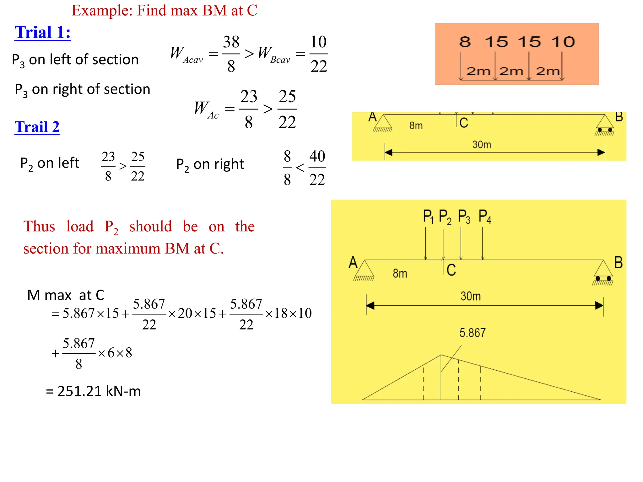
Trial 1:
38 10
822
Acav Bcav
W W
= =
P3 on right of section
23 25
8 22
Ac
W =
Trail 2
P3 on left of section
P2 on left 23 25
8 22
P2 on right 8 40
8 22
Thus load P2 should be on the
section for maximum BM at C.
M max at C
5.867 5.867
5.867 15 20 15 18 10
22 22
5.867
6 8
8
= + +
+
= 251.21 kN-m
Example: Find max BM at C
23.
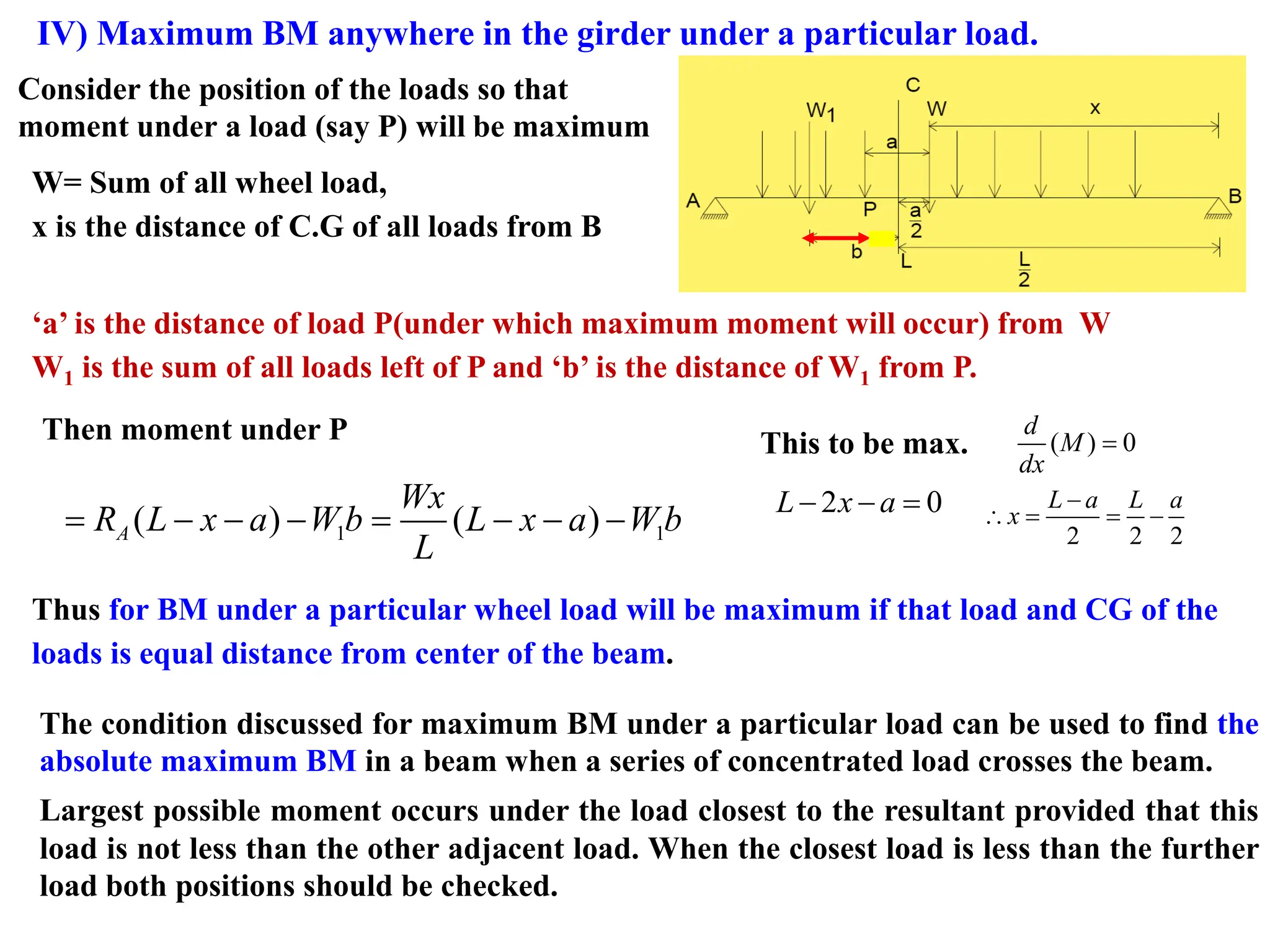
IV) Maximum BManywhere in the girder under a particular load.
Consider the position of the loads so that
moment under a load (say P) will be maximum
W= Sum of all wheel load,
x is the distance of C.G of all loads from B
‘a’ is the distance of load P(under which maximum moment will occur) from W
W1 is the sum of all loads left of P and ‘b’ is the distance of W1 from P.
Then moment under P
1 1
( ) ( )
= − − − = − − −
A
Wx
R L x a W b L x a W b
L
This to be max. ( ) 0
d
M
dx
=
2 0
L x a
− − =
2 2 2
L a L a
x
−
= = −
Thus for BM under a particular wheel load will be maximum if that load and CG of the
loads is equal distance from center of the beam.
The condition discussed for maximum BM under a particular load can be used to find the
absolute maximum BM in a beam when a series of concentrated load crosses the beam.
Largest possible moment occurs under the load closest to the resultant provided that this
load is not less than the other adjacent load. When the closest load is less than the further
load both positions should be checked.
24.
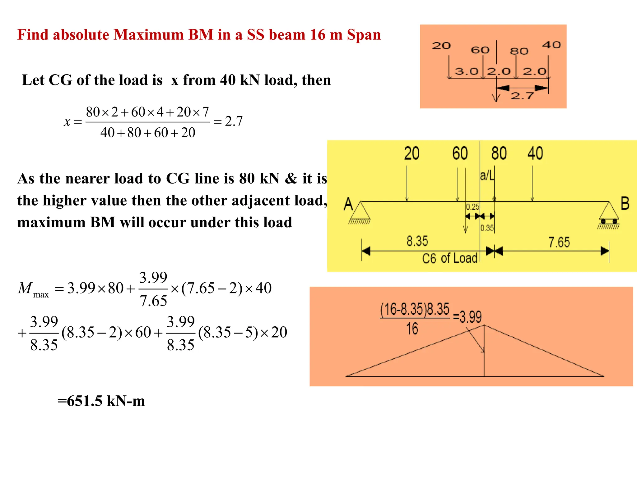
Let CG ofthe load is x from 40 kN load, then
80 2 60 4 20 7
2.7
40 80 60 20
x
+ +
= =
+ + +
As the nearer load to CG line is 80 kN & it is
the higher value then the other adjacent load,
maximum BM will occur under this load
max
3.99
3.99 80 (7.65 2) 40
7.65
3.99 3.99
(8.35 2) 60 (8.35 5) 20
8.35 8.35
M = + −
+ − + −
Find absolute Maximum BM in a SS beam 16 m Span
=651.5 kN-m