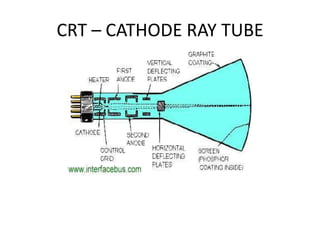
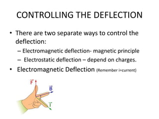
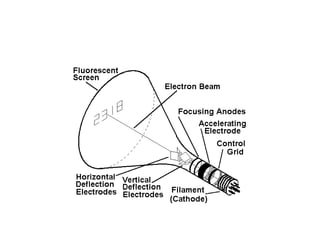
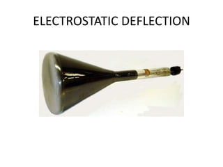
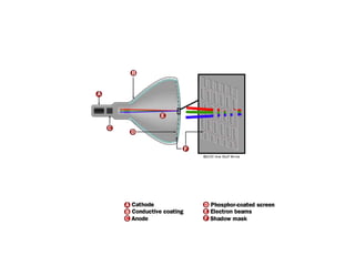
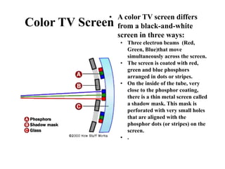
The document outlines the principles of operation for common display types in modern aircraft, including cathode ray tubes, light emitting diodes, and liquid crystal displays. It explains the methods for deflection control in CRTs and describes the differences between color and black-and-white screens. Additionally, it covers raster and stroke scanning, as well as the characteristics and operating principles of LED and LCD displays.
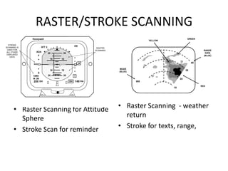
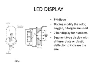


![Xc 245[1] (1)](https://cdn.slidesharecdn.com/ss_thumbnails/xc-24511-120923163558-phpapp01-thumbnail.jpg?width=640&height=640&fit=bounds)


