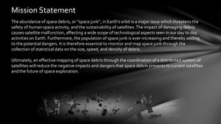
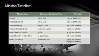
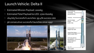
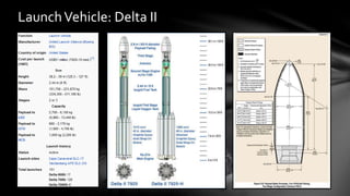
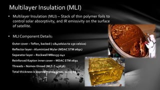
Tyler Hudgins
Yohan Kim
John Saleh
Daniel Shi
RichieTerwilliger
ME 355
Spring 2014
April 2, 2014
Critical Design Review
Mission Statement
The abundance of space debris, or “space junk”, in Earth’s orbit is a major issue which threatens the
safety of human space activity, and the sustainability of satellites.The impact of damaging debris
causes satellite malfunction, affecting a wide scope of technological aspects seen in our day to day
activities on Earth. Furthermore, the population of space junk is ever-increasing and thereby adding
to the potential dangers. It is therefore essential to monitor and map space junk through the
collection of statistical data on the size, speed, and density of debris.
Ultimately, an effective mapping of space debris through the coordination of a distributed system of
satellites will reduce the negative impacts and dangers that space debris presents to current satellites
and the future of space exploration.
Mission Objectives
Primary Objectives
• Create a more accurate and reliable catalogue of all space debris in LEO larger than 1 cm3, tracking
their orbits and velocities in an effort to protect satellites and future space missions from
potentially catastrophic damage.
Secondary Objectives
• Track space debris particles smaller than 1 cm3 in LEO, particularly ones at high velocity which could threaten
future missions.
• Collect data that could aid in the future removal of space junk.
Size of Object > 4 in .5 in – 4 in <0.5 in
Number of Objects 19,000 500,000 10,000,000
Space DebrisTracking
Focus Points of the Mission
• Many debris between 1-10 cm cannot be tracked. Impacts with objects of this size can
still result in severe damage, or complete destruction.
• Objects below 160 km undergo orbital decay. Due to residual air drag, these objects will
re-enter Earths atmosphere within a short period of time.
• A majority of manned missions as well as around 500/1000 operational satellites
operate in LEO (out to 2000 km).
• Approximately 40% of all tracked space debris is within the range 800-1100 km.
Orbit: 1000-3000 km Debris Size: 1-10 cm
Using a launch vehicle, three pairs of satellites will be
placed into low Earth orbit. Each pair will have its own
orbit, evenly spread between 1000 and 3000 km.
The six satellites will remain in their respective orbits
until sufficient data is collected on the debris within their
15 km camera range.
Each pair of satellites will then transfer to an orbit 15 km
inward, collecting new debris data until all space
between 1000km and 3000km has been catalogued.
Satellites will be disposed of through an orbital decay
trajectory, burning up on re-entry, or be placed in a
dormant orbital state.
Stage 1
Stage 2
Stage 3
Stage 4
Stag
e 1
Stage
2
Stage 3
Stage
4
3000
km
2333
km
1667
km
Concept of Operations
Vandenberg Air Force
Base, CA
July 1, 2018
MissionTimeline
Mission Stage Estimated CompletionTime Wet Mass
Launch July 1, 2018 2160 kg (All 6 sats)
Satellite Drop-Off July 1, 2018 2160 kg (All 6 sats)
SystemsTesting August , 2018 360 kg per satellite
Transfer to Initial Orbit September, 2018 357 kg per satellite
Data Collection in Orbit 30 days 357 kg per satellite
InwardTransfer to New Orbit 14-22 minutes 356 kg per satellite
Enters Dormancy September 2020 335 kg per satellite
(14 kg fuel reserve)
Launch Location:Vandenberg Air Force Base
LaunchVehicle: Delta II
• Estimated Mission Payload: 2000kg
• EstimatedTotal Payload to LEO: 2700-6100kg
• 164/165 Successful Launches: 99.4% success rate
• 96 consecutive successful launches since 1997
LaunchVehicle: Delta II
Orbital Mechanics
• V1 = 6511.9 m/s
• Vpt1 = 6509.3 m/s
• ΔV1 = 2.6 m/s
• V2 = 6517.1 m/s
• Vat1 = 6519.7 m/s
• ΔV2 = 2.6 m/s
• ΔVT1 = 5.2 m/s
• V2 = 6517.1 m/s
• Vpt2 = 6514.5 m/s
• ΔV2 = 2.6 m/s
• V3 = 6522.3 m/s
• Vat2 = 6524.9 m/s
• ΔV3 = 2.6 m/s
• ΔVT2 = 5.2 m/s
• Tsiolkovsky Rocket Equation:
• Δv=5.201855 (max)
• Ve = g * Isp = 9.8 * 236 = 2314
• M0 = Mf + M1
• Solving for Mf give us a value of .8169kg per burn
• With 22 total burns per satellite this give us a total of :
17.97 Kg
Fuel Calculations
∆𝑣 = 𝑣𝑒 ∗ ln(
𝑚 𝑜
𝑚1
)
Science PackageTechnology
• Thermal imaging camera will use Long Wave Infrared (LWIR) technology to
detect the heat of space debris against the absolute zero background of space.
• Instrumentation:
• DRS Technology has developed a LWIR camera for US military use that has
a pixel size of only 5 microns.
• Use this technology to make a light weight high resolution camera for use
in our satellite.
Estimated Specifications:
• Resolution: 5120 x 2880
(4x existing prototype)
• Dimensions: 1 cubic ft
• Power Required: 10 watts
• Mass: 10 kg
Data Processing
• Thermal Camera records the angle of the debris relative to the satellites
position.
• The angle of the debris along with the location and orientation of the satellite
are relayed to earth.
• This data is run through a Kalman filter to determine the velocity and orbit of
the particle.
• Atomic Clock
• AutoNAV
• AutoGNC
• Actuators – Reaction Wheels
General Controls:
General Electronics:
• CPU
• StarTracker
• Infrared Earth Sensor
• IMU
CPU: Mongoose-V MIPS R3000 Rad-Hard Processor
• Used in the New Horizons (Pluto Mission)
• MIPS R3000 Architecture
• 15MHz speed
• Radiation Protected
Telemetry,Tracking, and Command (TT&C)
Consist of five components:
• Transponder
• Power Amplifier
• Diplexer
• RF Network
• Antennas
• Optional -Wide BandTransceiver
• TDRSS (Tracking and Data Relay Satellite System)
• Reception Rate of 300 Mb/s in the Ka and Ku Bands
• Reception Rate of 800 Mb/s in the S band
• Transponding Rate of 25Mb/s in the Ka and Ku Bands
• Transponding Rate of 300 kb/s in the S Band
Communications Network
Antennas
• High Gain Antenna for backup emergency situations
• Parabola
• Diameter=1.6m
• PLANET-B, 1998
• Low Gain Antenna for uplink and downlink data
• Omni Directional
• Diameter= 106mm Long=1m
• ETS-VI, 1990's
Ka-Band
S-Band
Diplexer and Cables:
• Diplexer-FA27
• 19 oz
• Space Qualified
• RF Cables- Gore High Frequency 0.190” Cable
• 16 grams/foot
• Space Qualified
Transponders/Power Amplifier:
Space Qualified SGLSTT&CTransponder
Mass: 8kg
Temperature Limits: -34° C to +71° C
Data rate: up to 32 kbps on 1.7 Mhz subcarrier
Multi-Band High Rate Mission DataTransmitter (HRT-150)
Mass: 5lb
Temperature Limits: -34° C to +71° C
Radiation: 100krad
Data rate: 150Mbps
Thermal System Overview:
Components:
• Multi-Layer Insulation
• Flexible Heaters
• Louvre
Total Mass: 7.05 kg
Total Power: 415 w/h
Multilayer Insulation (MLI)
• Multilayer Insulation (MLI) – Stack of thin polymer foils to
control solar absorptivity, and IR emissivity on the surface
of satellite.
• MLI Component Details:
Outer cover – Teflon, backed (-184celsius to 150 celsius)
Reflector layer - Aluminized Mylar (MDAC STM 0691)
Separator layer – Rockwell MB0135-042
Reinforced Kapton inner cover – MDAC STM 0691
Threads – Nomex thread (MLT-T-43636)
Total thickness is approximately 5mm. 0.005 kg
KAPTON® Flexible Heaters
• Heater Component Details:
Electric heater
To maintain temperature range between -195°C and +200°C.
Dimension of 0.3m^2
5 Watts/in^2 = 7750.0155 W/m^2typical Watt Density
Power needed is 2325W.
Power needed for one hour in eclipse region: 2.4kWh
Louvres (radiator)
• Accommodates extreme variation of energy with little
temperature change, and saves heater power.
• Louvre Component Details:
Model name: 5K202 from a company called Orbital
Number of blades:10
Length: 0.2677 m
Width: 0.4050 m
Weight: 0.58 kg
Area: 0.108 m^2
Weight/Area: 5.37kg/m^2
Power: 15W
Needs 10 of them so 5.8kg for louvres.
Power System Overview
• Orbit: 2 hours, 30 min
• Maximum eclipse time (worse scenario) can be extended
to 40% of the period which is 60 min.
• In this eclipse region, only the nickel hydrogen battery will
be used to power up the satellite.
• As the satellite is out of eclipse region (1hr 30mins), the
solar panel should be able to recharge the battery (100Wh)
before reaching at the eclipse region.
Batteries: Nickel Hydrogen
• Satellite System Requires: 697.5 w
• Batteries (22 kg): 700 w
• Battery Component Details:
Model: SAR 10101
Mass: 22 kg
Length: 47 cm
Width: 33 cm
Height: 22 cm
Specific energy 33.1 Wh/kg
Volts: 28 V
Solar Panels
• Solar Panel Specs:
Intensity of the Sun: 1367 W/m^2
Solar Cell Efficiency: 22.5
Surface area of one side: 3.29m^2
Number of Solar Panels: 4
Packing Factor: 80%
Factor to accout for free rotation: ¼ [SMAD 416]
Light Induced Degradation of Si Cells per year: 3%
Operational Lifetime:
• Beginning of Life Power: 809.54 wh
• End of Life Power:When power level drops below 700wh
• This will occur 4.4 years after launch date
• After 4.4 years, the satellite could be considered
dysfunctional, as the thermal system could fail.
SatelliteThrusters and Engine System
The spacecraft propulsion system is required for 3 operations:
1. Orbit Insertion
2. Orbit Maintenance
3. Inward OrbitTransfers
The on-board propulsion system contains:
- 1x Aerojet MR-107 Monopropellant Engine
- 12x Aerojet MR-111 MonopropellantThruster
Thrusters and Engine System
Aerojet MR-107 Monopropellant Engine
Thrust (N) 275 N
Mass (kg) 1.01 kg
Aerojet MR-111 Monopropellant Engine
Thrust (N) 5 N
Mass (kg) 0.33 kg
PropellantTank
- Required Propellant: 17.97 kg (InwardTransfers),Total Estimate: 25 kg
- Density of Hydrazine (N2H4) = 1.021 kg/L
- Mission requires an estimated 25L of Hydrazine
Blowdown Monopropellant System Design
Plug and Play Satellite Design:
Air Force Research Laboratory
Internals Design
Fuel Tank
Reaction Wheels
Smart
Panels
Communications
Module
Host Computer
Signal-Processing
Module
Energy-Storage
Modules
Reaction Wheels
Host Computer
Communications Module
Signal-Processing Module
Fuel Tank
Internals Design
Exterior Design
Exterior Design
Orbital Debris Mapping

Orbital Debris Mapping

  • 1.
    Tyler Hudgins Yohan Kim JohnSaleh Daniel Shi RichieTerwilliger ME 355 Spring 2014 April 2, 2014 Critical Design Review
  • 2.
    Mission Statement The abundanceof space debris, or “space junk”, in Earth’s orbit is a major issue which threatens the safety of human space activity, and the sustainability of satellites.The impact of damaging debris causes satellite malfunction, affecting a wide scope of technological aspects seen in our day to day activities on Earth. Furthermore, the population of space junk is ever-increasing and thereby adding to the potential dangers. It is therefore essential to monitor and map space junk through the collection of statistical data on the size, speed, and density of debris. Ultimately, an effective mapping of space debris through the coordination of a distributed system of satellites will reduce the negative impacts and dangers that space debris presents to current satellites and the future of space exploration.
  • 3.
    Mission Objectives Primary Objectives •Create a more accurate and reliable catalogue of all space debris in LEO larger than 1 cm3, tracking their orbits and velocities in an effort to protect satellites and future space missions from potentially catastrophic damage. Secondary Objectives • Track space debris particles smaller than 1 cm3 in LEO, particularly ones at high velocity which could threaten future missions. • Collect data that could aid in the future removal of space junk.
  • 5.
    Size of Object> 4 in .5 in – 4 in <0.5 in Number of Objects 19,000 500,000 10,000,000 Space DebrisTracking
  • 6.
    Focus Points ofthe Mission • Many debris between 1-10 cm cannot be tracked. Impacts with objects of this size can still result in severe damage, or complete destruction. • Objects below 160 km undergo orbital decay. Due to residual air drag, these objects will re-enter Earths atmosphere within a short period of time. • A majority of manned missions as well as around 500/1000 operational satellites operate in LEO (out to 2000 km). • Approximately 40% of all tracked space debris is within the range 800-1100 km. Orbit: 1000-3000 km Debris Size: 1-10 cm
  • 7.
    Using a launchvehicle, three pairs of satellites will be placed into low Earth orbit. Each pair will have its own orbit, evenly spread between 1000 and 3000 km. The six satellites will remain in their respective orbits until sufficient data is collected on the debris within their 15 km camera range. Each pair of satellites will then transfer to an orbit 15 km inward, collecting new debris data until all space between 1000km and 3000km has been catalogued. Satellites will be disposed of through an orbital decay trajectory, burning up on re-entry, or be placed in a dormant orbital state. Stage 1 Stage 2 Stage 3 Stage 4 Stag e 1 Stage 2 Stage 3 Stage 4 3000 km 2333 km 1667 km Concept of Operations Vandenberg Air Force Base, CA July 1, 2018
  • 8.
    MissionTimeline Mission Stage EstimatedCompletionTime Wet Mass Launch July 1, 2018 2160 kg (All 6 sats) Satellite Drop-Off July 1, 2018 2160 kg (All 6 sats) SystemsTesting August , 2018 360 kg per satellite Transfer to Initial Orbit September, 2018 357 kg per satellite Data Collection in Orbit 30 days 357 kg per satellite InwardTransfer to New Orbit 14-22 minutes 356 kg per satellite Enters Dormancy September 2020 335 kg per satellite (14 kg fuel reserve)
  • 10.
  • 11.
    LaunchVehicle: Delta II •Estimated Mission Payload: 2000kg • EstimatedTotal Payload to LEO: 2700-6100kg • 164/165 Successful Launches: 99.4% success rate • 96 consecutive successful launches since 1997
  • 12.
  • 15.
    Orbital Mechanics • V1= 6511.9 m/s • Vpt1 = 6509.3 m/s • ΔV1 = 2.6 m/s • V2 = 6517.1 m/s • Vat1 = 6519.7 m/s • ΔV2 = 2.6 m/s • ΔVT1 = 5.2 m/s • V2 = 6517.1 m/s • Vpt2 = 6514.5 m/s • ΔV2 = 2.6 m/s • V3 = 6522.3 m/s • Vat2 = 6524.9 m/s • ΔV3 = 2.6 m/s • ΔVT2 = 5.2 m/s
  • 16.
    • Tsiolkovsky RocketEquation: • Δv=5.201855 (max) • Ve = g * Isp = 9.8 * 236 = 2314 • M0 = Mf + M1 • Solving for Mf give us a value of .8169kg per burn • With 22 total burns per satellite this give us a total of : 17.97 Kg Fuel Calculations ∆𝑣 = 𝑣𝑒 ∗ ln( 𝑚 𝑜 𝑚1 )
  • 18.
    Science PackageTechnology • Thermalimaging camera will use Long Wave Infrared (LWIR) technology to detect the heat of space debris against the absolute zero background of space. • Instrumentation: • DRS Technology has developed a LWIR camera for US military use that has a pixel size of only 5 microns. • Use this technology to make a light weight high resolution camera for use in our satellite. Estimated Specifications: • Resolution: 5120 x 2880 (4x existing prototype) • Dimensions: 1 cubic ft • Power Required: 10 watts • Mass: 10 kg
  • 19.
    Data Processing • ThermalCamera records the angle of the debris relative to the satellites position. • The angle of the debris along with the location and orientation of the satellite are relayed to earth. • This data is run through a Kalman filter to determine the velocity and orbit of the particle.
  • 22.
    • Atomic Clock •AutoNAV • AutoGNC • Actuators – Reaction Wheels General Controls:
  • 23.
    General Electronics: • CPU •StarTracker • Infrared Earth Sensor • IMU
  • 24.
    CPU: Mongoose-V MIPSR3000 Rad-Hard Processor • Used in the New Horizons (Pluto Mission) • MIPS R3000 Architecture • 15MHz speed • Radiation Protected
  • 26.
    Telemetry,Tracking, and Command(TT&C) Consist of five components: • Transponder • Power Amplifier • Diplexer • RF Network • Antennas • Optional -Wide BandTransceiver
  • 27.
    • TDRSS (Trackingand Data Relay Satellite System) • Reception Rate of 300 Mb/s in the Ka and Ku Bands • Reception Rate of 800 Mb/s in the S band • Transponding Rate of 25Mb/s in the Ka and Ku Bands • Transponding Rate of 300 kb/s in the S Band Communications Network
  • 28.
    Antennas • High GainAntenna for backup emergency situations • Parabola • Diameter=1.6m • PLANET-B, 1998 • Low Gain Antenna for uplink and downlink data • Omni Directional • Diameter= 106mm Long=1m • ETS-VI, 1990's Ka-Band S-Band
  • 29.
    Diplexer and Cables: •Diplexer-FA27 • 19 oz • Space Qualified • RF Cables- Gore High Frequency 0.190” Cable • 16 grams/foot • Space Qualified
  • 30.
    Transponders/Power Amplifier: Space QualifiedSGLSTT&CTransponder Mass: 8kg Temperature Limits: -34° C to +71° C Data rate: up to 32 kbps on 1.7 Mhz subcarrier Multi-Band High Rate Mission DataTransmitter (HRT-150) Mass: 5lb Temperature Limits: -34° C to +71° C Radiation: 100krad Data rate: 150Mbps
  • 32.
    Thermal System Overview: Components: •Multi-Layer Insulation • Flexible Heaters • Louvre Total Mass: 7.05 kg Total Power: 415 w/h
  • 33.
    Multilayer Insulation (MLI) •Multilayer Insulation (MLI) – Stack of thin polymer foils to control solar absorptivity, and IR emissivity on the surface of satellite. • MLI Component Details: Outer cover – Teflon, backed (-184celsius to 150 celsius) Reflector layer - Aluminized Mylar (MDAC STM 0691) Separator layer – Rockwell MB0135-042 Reinforced Kapton inner cover – MDAC STM 0691 Threads – Nomex thread (MLT-T-43636) Total thickness is approximately 5mm. 0.005 kg
  • 34.
    KAPTON® Flexible Heaters •Heater Component Details: Electric heater To maintain temperature range between -195°C and +200°C. Dimension of 0.3m^2 5 Watts/in^2 = 7750.0155 W/m^2typical Watt Density Power needed is 2325W. Power needed for one hour in eclipse region: 2.4kWh
  • 35.
    Louvres (radiator) • Accommodatesextreme variation of energy with little temperature change, and saves heater power. • Louvre Component Details: Model name: 5K202 from a company called Orbital Number of blades:10 Length: 0.2677 m Width: 0.4050 m Weight: 0.58 kg Area: 0.108 m^2 Weight/Area: 5.37kg/m^2 Power: 15W Needs 10 of them so 5.8kg for louvres.
  • 37.
    Power System Overview •Orbit: 2 hours, 30 min • Maximum eclipse time (worse scenario) can be extended to 40% of the period which is 60 min. • In this eclipse region, only the nickel hydrogen battery will be used to power up the satellite. • As the satellite is out of eclipse region (1hr 30mins), the solar panel should be able to recharge the battery (100Wh) before reaching at the eclipse region.
  • 38.
    Batteries: Nickel Hydrogen •Satellite System Requires: 697.5 w • Batteries (22 kg): 700 w • Battery Component Details: Model: SAR 10101 Mass: 22 kg Length: 47 cm Width: 33 cm Height: 22 cm Specific energy 33.1 Wh/kg Volts: 28 V
  • 39.
    Solar Panels • SolarPanel Specs: Intensity of the Sun: 1367 W/m^2 Solar Cell Efficiency: 22.5 Surface area of one side: 3.29m^2 Number of Solar Panels: 4 Packing Factor: 80% Factor to accout for free rotation: ¼ [SMAD 416] Light Induced Degradation of Si Cells per year: 3%
  • 40.
    Operational Lifetime: • Beginningof Life Power: 809.54 wh • End of Life Power:When power level drops below 700wh • This will occur 4.4 years after launch date • After 4.4 years, the satellite could be considered dysfunctional, as the thermal system could fail.
  • 42.
    SatelliteThrusters and EngineSystem The spacecraft propulsion system is required for 3 operations: 1. Orbit Insertion 2. Orbit Maintenance 3. Inward OrbitTransfers The on-board propulsion system contains: - 1x Aerojet MR-107 Monopropellant Engine - 12x Aerojet MR-111 MonopropellantThruster
  • 43.
    Thrusters and EngineSystem Aerojet MR-107 Monopropellant Engine Thrust (N) 275 N Mass (kg) 1.01 kg Aerojet MR-111 Monopropellant Engine Thrust (N) 5 N Mass (kg) 0.33 kg
  • 44.
    PropellantTank - Required Propellant:17.97 kg (InwardTransfers),Total Estimate: 25 kg - Density of Hydrazine (N2H4) = 1.021 kg/L - Mission requires an estimated 25L of Hydrazine
  • 45.
  • 47.
    Plug and PlaySatellite Design: Air Force Research Laboratory
  • 48.
    Internals Design Fuel Tank ReactionWheels Smart Panels Communications Module Host Computer Signal-Processing Module Energy-Storage Modules
  • 49.
    Reaction Wheels Host Computer CommunicationsModule Signal-Processing Module Fuel Tank Internals Design
  • 50.
  • 51.

Editor's Notes

  • #3 The abundance of space debris, or “space junk” in Earth’s orbit is a major issue for all space-fairing nations. This space debris threatens the safety of human space activity, and the sustainability of satellites. A reliable and accurate catalogue of space debris is a fundamental requirement for any effort towards debris collision avoidance. Impacts with debris causes satellite malfunction, affecting a wide scope of technological aspects seen in our day to day activities on Earth. Furthermore, the population of space junk is ever-increasing and thereby adding to the potential dangers. It is therefore essential to monitor and map space junk through the collection of statistical data on the size, speed, and orbit of debris. Ultimately, an effective mapping of space debris through the coordination of a distributed system of satellites will reduce the negative impacts and dangers that space debris presents to current satellites and the future of space exploration.