The KMEC mission involves sending two spacecraft to Saturn over 6 years to study cosmic dust, ultraviolet imaging, and space recognition between the payloads. Each spacecraft is octagonal and 6m tall, made of aluminum. The 100kg payload includes dust, UV, and ranging instruments. A chemical propulsion system will perform orbital maneuvers. Power comes from an RTG and backup battery. Thermal control uses an RTG and radiator. The spacecraft structure is sized to withstand launch stresses and the environment at Saturn.
Optimal trajectory to Saturn in ion-thruster powered spacecraftKristopherKerames
In this document, I derive the equations of motion for an ion-thruster powered spacecraft and use numerical methods to calculate its optimal trajectory to Saturn. I did this work within 48 hours for the University Physics Competition in 2020.
Orbit design for exoplanet discovery spacecraft dr dora musielak 1 april 2019Dora Musielak, Ph.D.
Most exoplanets have been discovered with space telescopes. Starting with an overview of rocket propulsion, this presentation introduces spacecraft trajectories in the Sun-Earth-Moon System, focusing especially on those appropriate for exoplanet detection spacecraft. It reviews past, present, and future exoplanet discovery missions.
The Centurion Orbit Transfer Vehicle (OTV) was part of our Aerospace Engineering Senior Design project at the University of Illinois at Urbana-Champaign. It is equipped with the latest technologies, including a nuclear thermal propulsion system. The structure weighs 89,000 kg and is capable of transporting cargo to Lagrange points L1 or L2.
Relativistic Effect in GPS Satellite and Computation of Time Error Vedant Srivastava
The satellites are the integral part of our life. In current scenario, our planet is covered with
thousands of satellites. These satellites covers every aspect of communication like- navigation,
telecommunication, television broadcasting, satellite imaginary, military communications,
Space Station, Earth's weather and climate etc. The small time delay in clock implemented in
satellites cause large delay in propagating signal and it leads to tremendous loss in
communication. This Project basically deals with detection and computation of time error on
satellite clock due to relativistic effect. The time delay is based on both special and general
relativity postulated by Albert Einstein in 1905 and 1915. The detection and computation had
been done by presenting the simulations in the MATLAB environment. The focus of project is
specially GPS satellites due to the need of better and reliable navigation system in current
scenario. Using the Simulink Environment in MATLAB a P code and C/A code have generated
and tested. These code contains timing signal and synchronization signal for GPS satellites.
Synchronizing time with precise time calculation on GPS receivers, system simulation in
MATLAB from GPS satellite transmitter to receiver will be discussed here. The atomic clock
is also discussed here which is used to measure the time delay with high level of precision
(around 10 nano-second) in satellites. Satellite Tool Kit (STK) Software a package
from Analytical Graphics, Inc. is also used in the project to model the satellite and its orbit
around the planet earth. It provides very high graphics simulation and modelling. It allows
engineers and scientists to perform complex analyses of all the physical parameters necessary
for satellite designing and communication.
S/C in Heliosynchronous Orbit - Spacecraft Environment AnalysisPau Molas Roca
Extended study of the general hazards a spacecraft
would face in a heliosynchronous orbit. Particularly, the radiation environment is deeply characterized. The main emphasis is made on the efects of radiation on two sensitivedevices projected to be on-board.
A kiloparsec scale_internal_shock_collision_in_the_jet_of_a_nearby_radio_galaxySérgio Sacani
Pesquisa feita com dados do Hubble mostram ondas de choque em colisão dentro dos chamados jatos extragalácticos emitidos pelos buracos negros supermassivos.
The SpaceDrive Project - First Results on EMDrive and Mach-Effect ThrustersSérgio Sacani
Propellantless propulsion is believed to be the best option for interstellar travel. However, photon rockets or solar sails have thrusts so low that maybe only nano-scaled spacecraft may reach the next star within our lifetime using very high-power laser beams. Following into the footsteps of earlier breakthrough propulsion programs, we are investigating different concepts based on non-classical/revolutionary propulsion ideas that claim to be at least an order of magnitude more efficient in producing thrust compared to photon rockets. Our intention is to develop an excellent research infrastructure to test new ideas and measure thrusts and/or artefacts with high confidence to determine if a concept works and if it does how to scale it up. At present, we are focusing on two possible revolutionary concepts: The EMDrive and the Mach-Effect Thruster. The first concept uses microwaves in a truncated cone-shaped cavity that is claimed to produce thrust. Although it is not clear on which theoretical basis this can work, several experimental tests have been reported in the literature, which warrants a closer examination. The second concept is believed to generate mass fluctuations in a piezo-crystal stack that creates non-zero time-averaged thrusts. Here we are reporting first results of our improved thrust balance as well as EMDrive and Mach-Effect thruster models. Special attention is given to the investigation and identification of error sources that cause false thrust signals. Our results show that the magnetic interaction from not sufficiently shielded cables or thrusters are a major factor that needs to be taken into account for proper μN thrust measurements for these type of devices.
Attitude & orbital control system, TTC & M system, Power system, Communication subsystem, Satellite antenna, Space qualification, Equipment Reliability, redundancy
1. KMEC
Mission to Saturn
ASTE 330 FALL 2016
Keyla Kolenovic, Melissa Dalton, Ethan Geipel, Christopher McDonough
2. Overall Mission Abstract
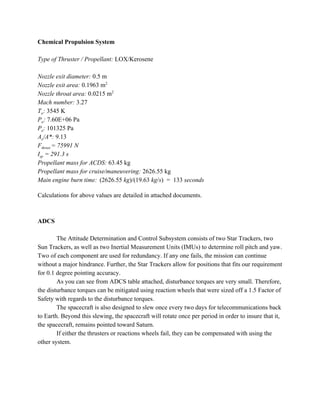
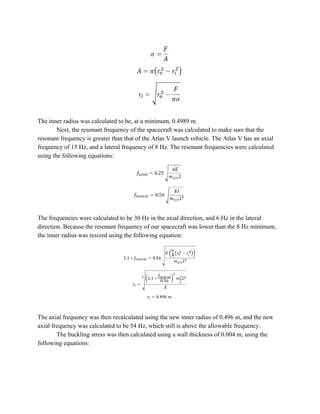
KMEC Description: The spacecraft, as pictured in Figure 1, has a octagonal cross section with a
distance of 1 m from edge to edge and a wall thickness of 0.004 m. The spacecraft is 6 m tall and
is comprised of two spacecraft that will separate upon entry to their orbit around Saturn. The
spacecraft will be made out of Aluminum, and the distribution of instruments within the frame is
shown below.
Figure 1: sketch of KMEC spacecraft. Fully assembled spacecraft
before payload deployment is on the left, the internal components of the payload
viewable in the center, and the cross sectional view of the spacecraft is on the right.
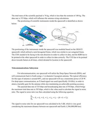
Level 1 Mission Requirements: This mission will dedicate 100 kg of payload to science, be
capable of transmitting 100 kpbs, use a chemical propulsion system, and have a backup battery
that will be capable of powering all subsystems for at least 24 hours. The 100 kg of payload
contains instruments that complete the following science objectives: cosmic dust analysis,
ultraviolet spectrometry imaging, and continuous space recognition between the main spacecraft
and deployed payload.
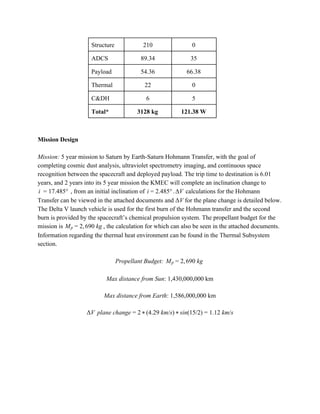
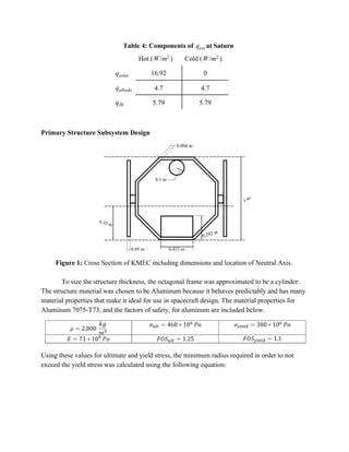
Table 1: Mass and Power Budget
Mass kg][ Power W][
Propulsion 2690 0
Power 26.5 n/a
Telecom 30 15
3. Structure 210 0
ADCS 89.34 35
Payload 54.36 66.38
Thermal 22 0
C&DH 6 5
Total* 3128 kg 121.38 W
Mission Design
Mission: 5 year mission to Saturn by Earth-Saturn Hohmann Transfer, with the goal of
completing cosmic dust analysis, ultraviolet spectrometry imaging, and continuous space
recognition between the spacecraft and deployed payload. The trip time to destination is 6.01
years, and 2 years into its 5 year mission the KMEC will complete an inclination change to
, from an initial inclination of . calculations for the Hohmann7.485°i = 1 .485°i = 2 VΔ
Transfer can be viewed in the attached documents and ΔV for the plane change is detailed below.
The Delta V launch vehicle is used for the first burn of the Hohmann transfer and the second
burn is provided by the spacecraft’s chemical propulsion system. The propellant budget for the
mission is , the calculation for which can also be seen in the attached documents., 90 kgMp = 2 6
Information regarding the thermal heat environment can be found in the Thermal Subsystem
section.
Propellant Budget: , 90 kgMp = 2 6
Max distance from Sun: 1,430,000,000 km
Max distance from Earth: 1,586,000,000 km
V plane change 4.29 km/s) in(15/2) .12 km/sΔ = 2 * ( * s = 1
4. Chemical Propulsion System
Type of Thruster / Propellant: LOX/Kerosene
Nozzle exit diameter: 0.5 m
Nozzle exit area: 0.1963 m2
Nozzle throat area: 0.0215 m2
Mach number: 3.27
To: 3545 K
Po: 7.60E+06 Pa
Pe: 101325 Pa
Ae/A*: 9.13
Fthrust = 75991 N
Isp = 291.3 s
Propellant mass for ACDS: 63.45 kg
Propellant mass for cruise/maneuvering: 2626.55 kg
Main engine burn time: 2626.55 kg)/(19.63 kg/s) 133 seconds( =
Calculations for above values are detailed in attached documents.
ADCS
The Attitude Determination and Control Subsystem consists of two Star Trackers, two
Sun Trackers, as well as two Inertial Measurement Units (IMUs) to determine roll pitch and yaw.
Two of each component are used for redundancy. If any one fails, the mission can continue
without a major hindrance. Further, the Star Trackers allow for positions that fits our requirement
for 0.1 degree pointing accuracy.
As you can see from ADCS table attached, disturbance torques are very small. Therefore,
the disturbance torques can be mitigated using reaction wheels that were sized off a 1.5 Factor of
Safety with regards to the disturbance torques.
The spacecraft is also designed to slew once every two days for telecommunications back
to Earth. Beyond this slewing, the spacecraft will rotate once per period in order to insure that it,
the spacecraft, remains pointed toward Saturn.
If either the thrusters or reactions wheels fail, they can be compensated with using the
other system.
5. C&DH
KMEC was identified to be on the higher end of a typical complexity mission, which
guided our estimates for the mass, power, and size of the C&DH subsystem. These estimates are
given below:
Mass Power Volume
6 kg 15 W 0.0085 m^3
Additionally, a C&DH flowchart was identified that is similar to the C&DH system that our
spacecraft would be based on:
This flowchart includes an IR camera as well as housekeeping data flow, which would be very
similar to the Ultraviolet Imaging System included on our spacecraft.
Power Subsystem
The power subsystem used for KMEC is a Multi-Mission Radioisotope Thermoelectric
Generator (MMRTG) of mass m = 4.06 kg with a fuel Pu-238. This was chosen as the primary
power source because it is, in part, modeled after the Cassini mission, wherein 3 RTG’s were
used. In addition, solar arrays would not have been a feasible option in terms of economy and
mass, as very little solar energy would be generated at such a large distance from the sun.
6. Thermal power generated from the MMRTG, as well as the resulting electrical power
conversion, can be seen in Table 2. This was calculated using the parameters for Pu-238 fuel
found in Table 3.
Table 2: MMRTG Sizing for Operation
Thermal (W) Electrical (W)
P,BOL 2,295.86 126.27
P,EOL 2,206.9 121.38
Table 3: Properties of Pu-238 MMRTG
As a backup power source, a LiSO2 battery was sized to provide power to all subsystems
for at least 24 hours. The size of the battery was determined to be m = 26.5 kg. There are no
solar arrays on KMEC, as due to Saturn’s distance from the sun, the little amount of solar energy
that could be produced by reasonably sized solar arrays wouldn’t merit their use, given the space,
mass, and cost of them.
Thermal Subsystem
The Thermal Subsystems is largely aided by the RTG. During the cold phase, the RTG
provides sufficient heat to keep our spacecraft within the operating temperatures of our
components.
During the hot phase, the RTG heat combined with the solar heat would warm our
spacecraft beyond our operational temperatures. Therefore, a radiator was installed with an area
of 1.420 square meters.
7. Table 4: Components of at Saturnqext
Hot ( )/mW 2 Cold ( )/mW 2
qsolar 16.92 0
qalbedo 4.7 4.7
qIR 5.79 5.79
Primary Structure Subsystem Design
Figure 1: Cross Section of KMEC including dimensions and location of Neutral Axis.
To size the structure thickness, the octagonal frame was approximated to be a cylinder.
The structure material was chosen to be Aluminum because it behaves predictably and has many
material properties that make it ideal for use in spacecraft design. The material properties for
Aluminum 7075-T73, and the factors of safety, for aluminum are included below.
Using these values for ultimate and yield stress, the minimum radius required in order to not
exceed the yield stress was calculated using the following equation:
8. The inner radius was calculated to be, at a minimum, 0.4989 m.
Next, the resonant frequency of the spacecraft was calculated to make sure that the
resonant frequency is greater than that of the Atlas V launch vehicle. The Atlas V has an axial
frequency of 15 Hz, and a lateral frequency of 8 Hz. The resonant frequencies were calculated
using the following equations:
The frequencies were calculated to be 30 Hz in the axial direction, and 6 Hz in the lateral
direction. Because the resonant frequency of our spacecraft was lower than the 8 Hz minimum,
the inner radius was resized using the following equation:
The axial frequency was then recalculated using the new inner radius of 0.496 m, and the new
axial frequency was calculated to be 54 Hz, which still is above the allowable frequency.
The buckling stress was then calculated using a wall thickness of 0.004 m, using the
following equations:
9. The buckling stress is much greater than any loads our spacecraft so it does not have to be
resized.
Finally, the mass of the structure was calculated as the following:
Payload Subsystem
The scientific payload for the KMEC mission had a limiting size of 100 kg. Our mission
focussed on obtaining data about the gravitational field, ultraviolet emissions, and cosmic dust in
the ring structure. The scientific instruments used were based on instruments from three unique
missions (GRACE, Juno, and Cassini).
The first instrument chosen was the K Band Ranging system (KBR) which was based on
the GRACE mission around Earth. This instrument tracks the distance between the two
spacecraft and uses fluctuations in that distance to map the gravitational field around the planet.
This would be the first attempt at using a KBR to map the gravitational field of a non-Earth
planet.
The second instrument is the Ultraviolet Imaging System (UVS) which was based on the
Juno mission around Jupiter. The focus of this mission was to obtain images and data regarding
the ultraviolet emissions of the planet, specifically near the aurora’s at the poles.
The third instrument is the Cosmic Dust Analyzer (DSA), which was based on the
Cassini mission around Saturn. This instrument detects and analyzes incredibly small particles
that pass through it, and then uses that information to shed light on the structure of the ring
systems around Saturn. Taking a CDA on this mission could allow for previously unknown ring
structures to be identified.
The breakdown for mass, power, volume, and data rates is given in the following table:
10. The total mass of the scientific payload is 76 kg, which is less than the restraint of 100 kg. The
data rate is 333 kbps, which will influence the antenna sizing calculations.
The positioning of scientific instruments inside the spacecraft is identified as shown
below:
The positioning of the instruments inside the spacecraft was modeled based on the GRACE
spacecraft, which utilized a semi-hexagonal frame, which was similar to our octagonal frame.
The CDA needed to be facing in the ram direction in order to collect its data, and the KBR has to
be pointed at the other spacecraft in order to collect its data correctly. The UVS has to be pointed
down towards Saturn at all times, which dictated its location in the spacecraft.
Telecommunications Subsystem
For telecommunication, our spacecraft will utilize the Deep Space Network (DSN), and
will communicate back to Earth using a 1 m diameter Cassegrain antenna. The typical efficiency
for this type of antenna is around 60%, and our spacecraft will use a transmitter power of 20 W.
For deep space communication, an X band signal was used (specifically 10 GHz), in order to
attain a tractable gain for the antenna while also maintaining an achievable pointing accuracy.
The payload data rate of 333 kbps and housekeeping data rate of 50 kbps, which brings
the maximum total data rate to 383 kbps, which is the value used to calculate the signal to noise
ratio. The signal to noise ratio was then calculated using the following equation:
The signal to noise ratio for our spacecraft was calculated to be 5 dB, which is very good
considering the maximum distance between our spacecraft and Earth (1,586,000,000 km).
11. Space Environment
Because Saturn is far from the Sun, solar radiation is not a large concern for the
spacecraft. Radiation given off by Saturn as well as the multimeroids that orbit the planet are a
concern, however. Orbiting at 2 million kilometers from Saturn’s surface, KMEC avoids the
harshest of Saturn’s radiation belt and multimeteroids. Nonetheless, KMEC was outfitted with a
half centimeter thick radiation shield made out of aluminum. Further copper shielding is added to
the instruments for extra radiation protection.
Our estimation for total radiation dose is 9000 rads, although this is likely to be higher
because it was modeled off of Earth’s radiation field which is weaker than Saturn’s.
Further Reading
https://saturn.jpl.nasa.gov/
https://www.nasa.gov/mission_pages/juno/main/index.html
http://grace.jpl.nasa.gov/mission/grace/
http://spaceflight101.com/juno/spacecraft-information/
https://directory.eoportal.org/web/eoportal/satellite-missions/g/grace
http://grace.jpl.nasa.gov/mission/grace/
http://www.engineersedge.com/calculators/section_square_case_18.htm
https://directory.eoportal.org/web/eoportal/satellite-missions/g/grail
https://saturn.jpl.nasa.gov/cosmic-dust-analyzer/
http://descanso.jpl.nasa.gov/DPSummary/Juno_DESCANSO_Post121106H--Compact.pdf