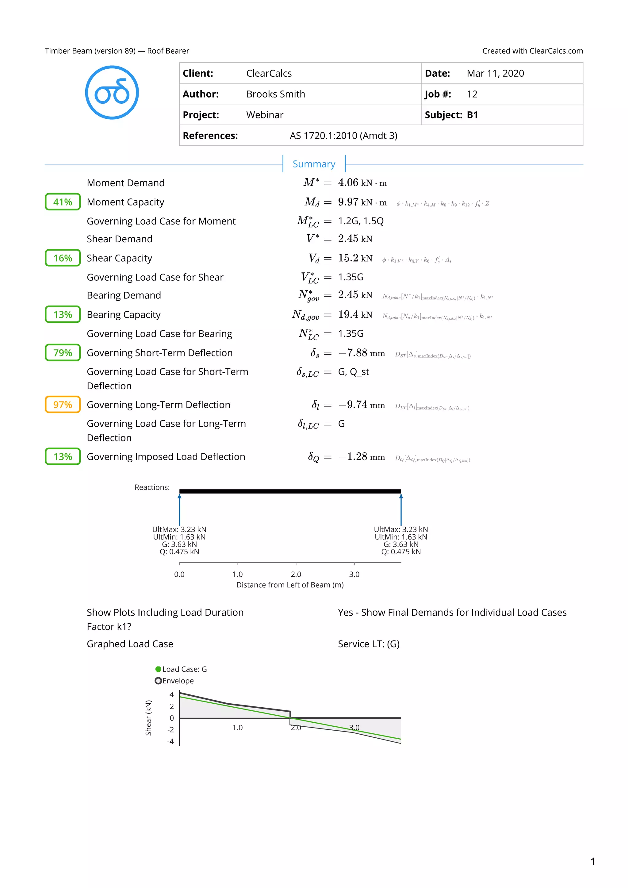
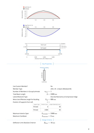
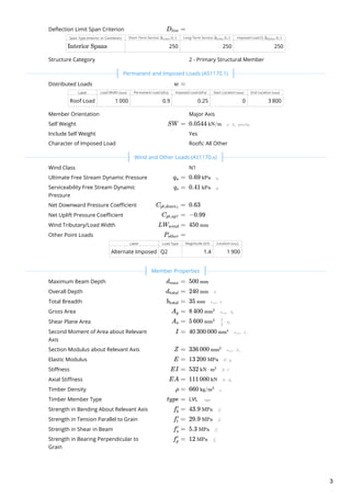
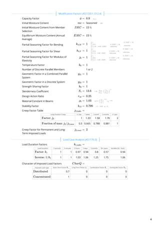
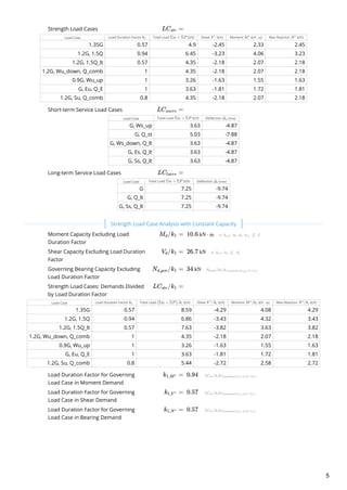
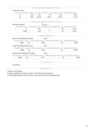
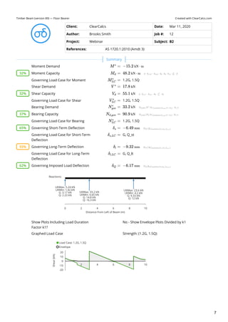
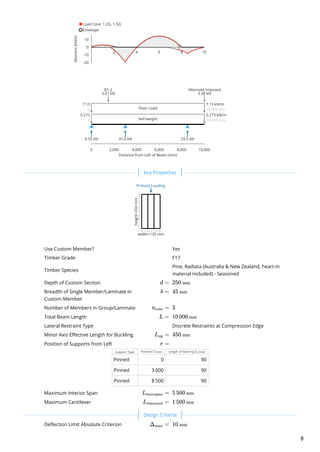
Created with ClearCalcs.comTimber Beam (version 89) — Roof Bearer
Client: ClearCalcs Date: Mar 11, 2020
Author: Brooks Smith Job #: 12
Project: Webinar Subject: B1
References: AS 1720.1:2010 (Amdt 3)
Moment Demand  
Moment Capacity  
Governing Load Case for Moment 1.2G, 1.5Q 
Shear Demand  
Shear Capacity  
Governing Load Case for Shear 1.35G 
Bearing Demand  
Bearing Capacity  
Governing Load Case for Bearing 1.35G 
Governing Short-Term Deflection  
Governing Load Case for Short-Term
Deflection
G, Q_st 
Governing Long-Term Deflection  
Governing Load Case for Long-Term
Deflection
G 
Governing Imposed Load Deflection  
Show Plots Including Load Duration
Factor k1?
Graphed Load Case
 
M =∗
4.06 kN ⋅ m
41% M ​ =d 9.97 kN ⋅ m
M ​ =LC
∗
V =∗
2.45 kN
16% V ​ =d 15.2 kN
V ​ =LC
∗
N ​ =gov
∗
2.45 kN
13% N ​ =d,gov 19.4 kN
N ​ =LC
∗
79% δ ​ =s −7.88 mm
δ ​ =s,LC
97% δ ​ =l −9.74 mm
δ ​ =l,LC
13% δ ​ =Q −1.28 mm
Reactions:
Distance from Left of Beam (m)
0.0 1.0 2.0 3.0
UltMax: 3.23 kN
UltMin: 1.63 kN
G: 3.63 kN
Q: 0.475 kN
UltMax: 3.23 kN
UltMin: 1.63 kN
G: 3.63 kN
Q: 0.475 kN
Yes - Show Final Demands for Individual Load Cases
Service LT: (G)
Load Case: G
Envelope
1.0 2.0 3.0
Shear(kN)
-4
-2
0
2
4
Summary
1
Use Custom Member?
Member Type
Number of Members in Group/Laminate  
Total Beam Length  
Lateral Restraint Type
Minor Axis Effective Length for Buckling  
Position of Supports from Left
Support Type Position ( ) Length of Bearing ( )
Pinned 0 90
Pinned 3 800 90
Maximum Interior Span  
Maximum Cantilever  
Deflection Limit Absolute Criterion  
Load Case: G
Envelope
1.0 2.0 3.0
Moment(kNm)
0.0
1.0
2.0
3.0
4.0
Long-Term LC: G
Envelope 1.0 2.0 3.0
Deflection(mm)
-10
-8
-6
-4
-2
0
Distance from Left of Beam (mm)
0 1,000 2,000 3,000
Self-weight
0.109
0 3 800 mm
0.109 kN/m
Roof Load
1.8
0 3 800 mm
1.8 kN/m
3.63 kN 3.63 kN
 
d=240mm
b=35 mm
Primary Loading
No
240 x 35 - e-beam (Wesbeam®)
n ​ =com 1
L = 3 800 mm
Discrete Restraints at Compression Edge
L ​ =ay 600 mm
r =
l mm l ​
b mm
L ​ =maxspan 3 800 mm
L ​ =maxcant 0 mm
 
Δ ​ =max 10 mm
Key Properties
Design Criteria
2
Deflection Limit Span Criterion
Span Type (Interior or Cantilever) Short-Term Service ( ) Long-Term Service ( ) Imposed Load Q ( )
250 250 250
Structure Category
Distributed Loads
Label Load Width ( ) Permanent Load ( ) Imposed Load ( ) Start Location ( ) End Location ( )
Roof Load 1 000 0.9 0.25 0 3 800
Member Orientation
Self Weight  
Include Self Weight
Character of Imposed Load
Wind Class
Ultimate Free Stream Dynamic Pressure  
Serviceability Free Stream Dynamic
Pressure
 
Net Downward Pressure Coefficient  
Net Uplift Pressure Coefficient  
Wind Tributary/Load Width  
Other Point Loads
Label Load Type Magnitude ( ) Location ( )
Alternate Imposed Q2 1.4 1 900
Maximum Beam Depth  
Overall Depth  
Total Breadth  
Gross Area  
Shear Plane Area  
Second Moment of Area about Relevant
Axis
 
Section Modulus about Relevant Axis  
Elastic Modulus  
Stiffness  
Axial Stiffness  
Timber Density  
Timber Member Type LVL 
Strength in Bending About Relevant Axis  
Strength in Tension Parallel to Grain  
Strength in Shear in Beam  
Strength in Bearing Perpendicular to
Grain
 
D ​ =lim
Δ ​
s,lim L/ Δ ​
l,lim L/ Δ ​
Q,lim L/
Interior Spans
2 - Primary Structural Member
 
w =
mm kPa kPa mm mm
Major Axis
SW = 0.0544 kN/m
Yes
Roofs: All Other
 
N1
q ​ =u 0.69 kPa
q ​ =s 0.41 kPa
C ​ =pt,down↓ 0.63
C ​ =pt,up↑ −0.99
LW ​ =wind 450 mm
P ​ =other
kN mm
 
d ​ =max 500 mm
d ​ =total 240 mm
b ​ =total 35 mm
A ​ =g 8 400 mm2
A ​ =s 5 600 mm2
I = 40 300 000 mm4
Z = 336 000 mm3
E = 13 200 MPa
EI = 532 kN ⋅ m2
EA = 111 000 kN
ρ = 660 kg/m3
type =
f ​ =b
′
43.9 MPa
f ​ =t
′
29.9 MPa
f ​ =s
′
5.3 MPa
f ​ =p
′
12 MPa
Permanent and Imposed Loads (AS1170.1)
Wind and Other Loads (AS1170.x)
Member Properties
3
Capacity Factor  
Initial Moisture Content Seasoned 
Initial Moisture Content from Member
Selection
 
Equilibrium Moisture Content (Annual
Average)
 
Partial Seasoning Factor for Bending
Partial Seasoning Factor for Shear  
Partial Seasoning Factor for Modulus of
Elasticity
 
Temperature Factor  
Number of Discrete Parallel Members
Geometric Factor in a Combined Parallel
System
 
Geometric Factor in a Discrete System  
Strength Sharing Factor  
Slenderness Coefficient  
Design Action Ratio  
Material Constant in Beams  
Stability Factor  
Creep Factor Table
Long-Duration Creep ≤1 day 1 week 1 month 3 months ≥1 year
1 1.33 1.58 1.76 2
0.5 0.665 0.788 0.881 1
Creep Factor for Permanent and Long-
Term Imposed Loads
 
Load Duration Factors
Load Duration: 5 seconds 5 minutes 5 hours 5 days 5 months 50+ years Variable (5d - 5mo)
1 1 0.97 0.94 0.8 0.57 0.94
1 1 1.03 1.06 1.25 1.75 1.06
Character of Imposed Load Factors
Imposed Load Type Short-Term Factor Long-Term Factor Combination Factor Earthquake Factor
0.7 0 0 0
1 0 0 0
 
ϕ = 0.9
mc =
IMC = 15 %
EMC = 15 %
k ​ =4,M 1
k ​ =4,V 1
j ​ =6 1
k ​ =6 1
1 or 2
g ​ =31 1
g ​ =32 1
k ​ =9 1
S ​ =1 13.6
r ​ =ub 0.25
ρ ​ =b 1.03
k ​ =12 0.799
j ​ =2,table
Factor: j ​
2
Fraction of max: j ​/j ​
2 2,max
j ​ =2,max 2
 
k ​ =1,table
Factor: k ​
1
Inverse: 1/k ​
1
CharQ =
Ψ ​
s ψ ​
l Ψ ​
c Ψ ​
E
Distributed
Concentrated
Modification Factors (AS1720.1, Cl 2.4)
Load Case Analysis (AS1170.0)
4
Strength Load Cases
Load Case Load Duration Factor Total Load ( ) Shear ( ) Moment ( ) Max Reaction ( )
1.35G 0.57 4.9 -2.45 2.33 2.45
1.2G, 1.5Q 0.94 6.45 -3.23 4.06 3.23
1.2G, 1.5Q_lt 0.57 4.35 -2.18 2.07 2.18
1.2G, Wu_down, Q_comb 1 4.35 -2.18 2.07 2.18
0.9G, Wu_up 1 3.26 -1.63 1.55 1.63
G, Eu, Q_E 1 3.63 -1.81 1.72 1.81
1.2G, Su, Q_comb 0.8 4.35 -2.18 2.07 2.18
Short-term Service Load Cases
Load Case Total Load ( ) Deflection ( )
G, Ws_up 3.63 -4.87
G, Q_st 5.03 -7.88
G, Ws_down, Q_lt 3.63 -4.87
G, Es, Q_lt 3.63 -4.87
G, Ss, Q_lt 3.63 -4.87
Long-term Service Load Cases
Load Case Total Load ( ) Deflection ( )
G 7.25 -9.74
G, Q_lt 7.25 -9.74
G, Ss, Q_lt 7.25 -9.74
Moment Capacity Excluding Load
Duration Factor
 
Shear Capacity Excluding Load Duration
Factor
 
Governing Bearing Capacity Excluding
Load Duration Factor
 
Strength Load Cases: Demands Divided
by Load Duration Factor
Load Case Load Duration Factor Total Load ( ) Shear ( ) Moment ( ) Max Reaction ( )
1.35G 0.57 8.59 -4.29 4.08 4.29
1.2G, 1.5Q 0.94 6.86 -3.43 4.32 3.43
1.2G, 1.5Q_lt 0.57 7.63 -3.82 3.63 3.82
1.2G, Wu_down, Q_comb 1 4.35 -2.18 2.07 2.18
0.9G, Wu_up 1 3.26 -1.63 1.55 1.63
G, Eu, Q_E 1 3.63 -1.81 1.72 1.81
1.2G, Su, Q_comb 0.8 5.44 -2.72 2.58 2.72
Load Duration Factor for Governing
Load Case in Moment Demand
 
Load Duration Factor for Governing
Load Case in Shear Demand
 
Load Duration Factor for Governing
Load Case in Bearing Demand
 
LC ​ =str
k ​
1 Σw + ΣP kN V ∗
kN M∗
kN ⋅ m N∗
kN
LC ​ =sserv
Σw + ΣP kN Δ ​
s mm
LC ​ =lserv
Σw + ΣP kN Δ ​
l mm
 
M ​/k ​ =d 1 10.6 kN ⋅ m
V ​/k ​ =d 1 26.7 kN
N ​/k ​ =d,gov 1 34 kN
LC ​/k ​ =str 1
k ​
1 (Σw + ΣP)/k ​
1 kN V /k ​
∗
1 kN M /k ​
∗
1 kN ⋅ m N /k ​
∗
1 kN
k ​ =1,M∗ 0.94
k ​ =1,V ∗ 0.57
k ​ =1,N∗ 0.57
Strength Load Case Analysis with Constant Capacity
5
Unfactored Load
Load Type Total Load ( ) Shear ( ) Moment ( ) Max Reaction ( ) Short-Term Deflection ( )
G 3.63 -1.81 1.72 1.81 -4.87
Q 0.95 -0.475 0.451 0.475 -1.28
Bearing Utilisation
Support Location ( ) Bearing Demand ( ) Bearing Factor Bearing Capacity ( ) Bearing Utilisation
0 4.29 1 34 0.126
3 800 4.29 1 34 0.126
Short-Term Deflection Per Span
Span Length ( ) Span Type Short-Term Deflection ( ) Short-term Deflection Limit ( ) Deflection Utilisation
3 800 Int -7.88 10 0.788
Long-Term Deflection Per Span
Span Length ( ) Span Type Long-Term Deflection ( ) Long-term Deflection Limit ( ) Deflection Utilisation
3 800 Int -9.74 10 0.974
Imposed Load Deflection Per Span
Span Length ( ) Span Type Imposed Load Deflection ( ) Imposed Load Deflection Limit ( ) Deflection Utilisation
3 800 Int -1.28 10 0.128
Comments
Beam is not notched
Default equilibrium moisture content is 15% (most non-exposed use)
Default fully-loaded moisture content is less than 25% (most non-exposed use)
 
Σw + ΣP kN V ∗
kN M∗
kN ⋅ m R∗
kN Δ ​
s mm
 
N ​ =d,table
l mm N /k ​
∗
1 kN k ​
7 N ​/k ​
d 1 kN N /N ​
∗
d
 
D ​ =ST
L mm Δ ​
s mm Δ ​
s,lim mm Δ ​/Δ ​
s s,lim
D ​ =LT
L mm Δ ​
l mm Δ ​
l,lim mm Δ ​/Δ ​
l l,lim
D ​ =Q
L mm Δ ​
Q mm Δ ​
Q,lim mm Δ ​/Δ ​
Q Q,lim
 
 
1.
2.
3.
Unfactored Load Analysis (AS1170.0)
Bearing Capacity (AS 1720.1:2010, Cl 3.2.6)
Deflection Analysis
Comments
Assumptions
6
Created with ClearCalcs.comTimber Beam (version 89) — Floor Bearer
Client: ClearCalcs Date: Mar 11, 2020
Author: Brooks Smith Job #: 12
Project: Webinar Subject: B2
References: AS 1720.1:2010 (Amdt 3)
Moment Demand  
Moment Capacity  
Governing Load Case for Moment 1.2G, 1.5Q 
Shear Demand  
Shear Capacity  
Governing Load Case for Shear 1.2G, 1.5Q 
Bearing Demand  
Bearing Capacity  
Governing Load Case for Bearing 1.2G, 1.5Q 
Governing Short-Term Deflection  
Governing Load Case for Short-Term
Deflection
G, Q_st 
Governing Long-Term Deflection  
Governing Load Case for Long-Term
Deflection
G, Q_lt 
Governing Imposed Load Deflection  
Show Plots Including Load Duration
Factor k1?
Graphed Load Case
 
M =∗
−15.2 kN ⋅ m
32% M ​ =d 48.2 kN ⋅ m
M ​ =LC
∗
V =∗
17.8 kN
32% V ​ =d 55.1 kN
V ​ =LC
∗
N ​ =gov
∗
33.2 kN
37% N ​ =d,gov 90.9 kN
N ​ =LC
∗
65% δ ​ =s −6.49 mm
δ ​ =s,LC
93% δ ​ =l −9.32 mm
δ ​ =l,LC
62% δ ​ =Q −6.17 mm
Reactions:
Distance from Left of Beam (m)
0 2 4 6 8 10
UltMax: 5.24 kN
UltMin: 1.42 kN
G: 3.17 kN
Q: 2.23 kN
UltMax: 33.2 kN
UltMin: 6.65 kN
G: 14.8 kN
Q: 16.3 kN
UltMax: 23.6 kN
UltMin: 4.2 kN
G: 9.33 kN
Q: 12 kN
No - Show Envelope Plots Divided by k1
Strength: (1.2G, 1.5Q)
Load Case: 1.2G, 1.5Q
Envelope
2 4 6 8 10
Shear(kN)
-20
-10
0
10
20
Summary
7
Use Custom Member?
Timber Grade
Timber Species
Depth of Custom Section  
Breadth of Single Member/Laminate in
Custom Member
 
Number of Members in Group/Laminate  
Total Beam Length  
Lateral Restraint Type
Minor Axis Effective Length for Buckling  
Position of Supports from Left
Support Type Position ( ) Length of Bearing ( )
Pinned 0 90
Pinned 3 000 90
Pinned 8 500 90
Maximum Interior Span  
Maximum Cantilever  
Deflection Limit Absolute Criterion  
Load Case: 1.2G, 1.5Q
Envelope
2 4 6 8 10
Moment(kNm)
-20
-10
0
10
Distance from Left of Beam (mm)
0 2,000 4,000 6,000 8,000 10,000
Self-weight
0.273
0 10 000 mm
0.273 kN/m
Floor Load
7.13
0 10 000 mm
7.13 kN/m
B1-2
3.61 kN
Alternate Imposed
3.38 kN
6.55 kN 41.6 kN 29.5 kN
 
width=135 mm
height=250mm
Primary Loading
Yes
F17
Pine, Radiata (Australia & New Zealand, heart-in
material included) - Seasoned
d = 250 mm
b = 45 mm
n ​ =com 3
L = 10 000 mm
Discrete Restraints at Compression Edge
L ​ =ay 450 mm
r =
l mm l ​
b mm
L ​ =maxspan 5 500 mm
L ​ =maxcant 1 500 mm
 
Δ ​ =max 10 mm
Key Properties
Design Criteria
8
Deflection Limit Span Criterion
Span Type (Interior or Cantilever) Short-Term Service ( ) Long-Term Service ( ) Imposed Load Q ( )
300 300 300
150 150 150
Structure Category
Distributed Loads
Label Load Width ( ) Permanent Load ( ) Imposed Load ( ) Start Location ( ) End Location ( )
Floor Load 2 000 0.5 1.5 0 10 000
Point Loads
Label Permanent Load ( ) Imposed Load ( ) Location ( )
B1-2 1.81 0.475 1 500
Member Orientation
Self Weight  
Include Self Weight
Character of Imposed Load
Wind Class
Ultimate Free Stream Dynamic Pressure  
Serviceability Free Stream Dynamic
Pressure
 
Net Downward Pressure Coefficient  
Net Uplift Pressure Coefficient  
Wind Tributary/Load Width  
Other Point Loads
Label Load Type Magnitude ( ) Location ( )
Alternate Imposed Q2 1.8 10 000
Maximum Beam Depth  
Overall Depth  
Total Breadth  
Gross Area  
Shear Plane Area  
Second Moment of Area about Relevant
Axis
 
Section Modulus about Relevant Axis  
Elastic Modulus  
Stiffness  
Axial Stiffness  
Timber Density  
Timber Member Type Sawn High Grade 
Strength in Bending About Relevant Axis  
Strength in Tension Parallel to Grain  
D ​ =lim
Δ ​
s,lim L/ Δ ​
l,lim L/ Δ ​
Q,lim L/
Interior Spans
Cantilevers
2 - Primary Structural Member
 
w =
mm kPa kPa mm mm
P =
kN kN mm
Major Axis
SW = 0.182 kN/m
Yes
Floors: Residential and Domestic
 
N1
q ​ =u 0.69 kPa
q ​ =s 0.41 kPa
C ​ =pt,down↓ 0
C ​ =pt,up↑ 0
LW ​ =wind 450 mm
P ​ =other
kN mm
 
d ​ =max 500 mm
d ​ =total 250 mm
b ​ =total 135 mm
A =g 33 800 mm2
A ​ =s 22 500 mm2
I = 176 000 000 mm4
Z = 1 410 000 mm3
E = 14 000 MPa
EI = 2 460 kN ⋅ m2
EA = 473 000 kN
ρ = 550 kg/m3
type =
f ​ =b
′
42 MPa
f ​ =t
′
22 MPa
Permanent and Imposed Loads (AS1170.1)
Wind and Other Loads (AS1170.x)
Member Properties
9
Strength in Shear in Beam  
Strength in Bearing Perpendicular to
Grain
 
Capacity Factor  
Initial Moisture Content Seasoned 
Initial Moisture Content from Member
Selection
 
Equilibrium Moisture Content (Annual
Average)
 
Partial Seasoning Factor for Bending  
Partial Seasoning Factor for Shear  
Partial Seasoning Factor for Modulus of
Elasticity
 
Temperature Factor  
Number of Discrete Parallel Members
Geometric Factor in a Combined Parallel
System
 
Geometric Factor in a Discrete System  
Strength Sharing Factor  
Slenderness Coefficient  
Design Action Ratio  
Material Constant in Beams  
Stability Factor  
Creep Factor Table
Long-Duration Creep ≤1 day 1 week 1 month 3 months ≥1 year
1 1.33 1.58 1.76 2
0.5 0.665 0.788 0.881 1
Creep Factor for Permanent and Long-
Term Imposed Loads
 
Load Duration Factors
Load Duration: 5 seconds 5 minutes 5 hours 5 days 5 months 50+ years Variable (5d - 5mo)
1 1 0.97 0.94 0.8 0.57 0.8
1 1 1.03 1.06 1.25 1.75 1.25
Character of Imposed Load Factors
Imposed Load Type Short-Term Factor Long-Term Factor Combination Factor Earthquake Factor
0.7 0.4 0.4 0.3
1 0.4 0.4 0.3
f ​ =s
′
3.6 MPa
f ​ =p
′
10 MPa
 
ϕ = 0.85
mc =
IMC = 15 %
EMC = 15 %
k ​ =4,M 1
k ​ =4,V 1
j ​ =6 1
k ​ =6 1
1 or 2
g ​ =31 1.2
g ​ =32 1.2
k ​ =9 1.2
S ​ =1 3.11
r ​ =ub 0.25
ρ ​ =b 0.985
k ​ =12 1
j ​ =2,table
Factor: j ​
2
Fraction of max: j ​/j ​
2 2,max
j ​ =2,max 2
 
k ​ =1,table
Factor: k ​
1
Inverse: 1/k ​
1
CharQ =
Ψ ​
s ψ ​
l Ψ ​
c Ψ ​
E
Distributed
Concentrated
Modification Factors (AS1720.1, Cl 2.4)
Load Case Analysis (AS1170.0)
10
Strength Load Cases
Load Case Load Duration Factor Total Load ( ) Shear ( ) Moment ( ) Max Reaction ( )
1.35G 0.57 18.4 -5.1 -4.44 9.97
1.2G, 1.5Q 0.8 62.1 17.8 -15.2 33.2
1.2G, 1.5Q_lt 0.57 34.6 9.73 -8.47 18.6
1.2G, Wu_down, Q_comb 1 28.6 7.93 -6.96 15.4
0.9G, Wu_up 1 12.3 -3.4 -2.96 6.65
G, Eu, Q_E 1 22.8 6.31 -5.55 12.3
1.2G, Su, Q_comb 0.8 28.6 7.93 -6.96 15.4
Short-term Service Load Cases
Load Case Total Load ( ) Deflection ( )
G, Ws_up 13.6 -2.19
G, Q_st 35.1 -6.49
G, Ws_down, Q_lt 25.8 -4.66
G, Es, Q_lt 25.8 -4.66
G, Ss, Q_lt 25.8 -4.66
Long-term Service Load Cases
Load Case Total Load ( ) Deflection ( )
G 27.3 -4.38
G, Q_lt 51.6 -9.32
G, Ss, Q_lt 51.6 -9.32
Moment Capacity Excluding Load
Duration Factor
 
Shear Capacity Excluding Load Duration
Factor
 
Governing Bearing Capacity Excluding
Load Duration Factor
 
Strength Load Cases: Demands Divided
by Load Duration Factor
Load Case Load Duration Factor Total Load ( ) Shear ( ) Moment ( ) Max Reaction ( )
1.35G 0.57 32.3 -8.94 -7.79 17.5
1.2G, 1.5Q 0.8 77.6 22.3 -19.1 41.6
1.2G, 1.5Q_lt 0.57 60.8 17.1 -14.9 32.7
1.2G, Wu_down, Q_comb 1 28.6 7.93 -6.96 15.4
0.9G, Wu_up 1 12.3 -3.4 -2.96 6.65
G, Eu, Q_E 1 22.8 6.31 -5.55 12.3
1.2G, Su, Q_comb 0.8 35.7 9.91 -8.7 19.2
Load Duration Factor for Governing
Load Case in Moment Demand
 
Load Duration Factor for Governing
Load Case in Shear Demand
 
Load Duration Factor for Governing
Load Case in Bearing Demand
 
LC ​ =str
k ​
1 Σw + ΣP kN V ∗
kN M∗
kN ⋅ m N∗
kN
LC ​ =sserv
Σw + ΣP kN Δ ​
s mm
LC ​ =lserv
Σw + ΣP kN Δ ​
l mm
 
M ​/k ​ =d 1 60.2 kN ⋅ m
V ​/k ​ =d 1 68.9 kN
N ​/k ​ =d,gov 1 114 kN
LC ​/k ​ =str 1
k ​
1 (Σw + ΣP)/k ​
1 kN V /k ​
∗
1 kN M /k ​
∗
1 kN ⋅ m N /k ​
∗
1 kN
k ​ =1,M∗ 0.8
k ​ =1,V ∗ 0.8
k ​ =1,N∗ 0.8
Strength Load Case Analysis with Constant Capacity
11
Unfactored Load
Load Type Total Load ( ) Shear ( ) Moment ( ) Max Reaction ( ) Short-Term Deflection ( )
G 13.6 -3.78 -3.29 7.38 -2.19
Q 30.5 9.01 -7.53 16.3 -6.17
Bearing Utilisation
Support Location ( ) Bearing Demand ( ) Bearing Factor Bearing Capacity ( ) Bearing Utilisation
0 6.55 1 103 0.0634
3 000 41.6 1.1 114 0.366
8 500 29.5 1.1 114 0.26
Short-Term Deflection Per Span
Span Length ( ) Span Type Short-Term Deflection ( ) Short-term Deflection Limit ( ) Deflection Utilisation
3 000 Int -0.381 10 0.0381
5 500 Int -6.49 10 0.649
1 500 Cant 4.1 10 0.41
Long-Term Deflection Per Span
Span Length ( ) Span Type Long-Term Deflection ( ) Long-term Deflection Limit ( ) Deflection Utilisation
3 000 Int -0.542 10 0.0542
5 500 Int -9.32 10 0.932
1 500 Cant 5.87 10 0.587
Imposed Load Deflection Per Span
Span Length ( ) Span Type Imposed Load Deflection ( ) Imposed Load Deflection Limit ( ) Deflection Utilisation
3 000 Int 0.516 10 0.0516
5 500 Int -6.17 10 0.617
1 500 Cant 3.92 10 0.392
Comments
Beam is not notched
Default equilibrium moisture content is 15% (most non-exposed use)
Default fully-loaded moisture content is less than 25% (most non-exposed use)
 
Σw + ΣP kN V ∗
kN M∗
kN ⋅ m R∗
kN Δ ​
s mm
 
N ​ =d,table
l mm N /k ​
∗
1 kN k ​
7 N ​/k ​
d 1 kN N /N ​
∗
d
 
D ​ =ST
L mm Δ ​
s mm Δ ​
s,lim mm Δ ​/Δ ​
s s,lim
D ​ =LT
L mm Δ ​
l mm Δ ​
l,lim mm Δ ​/Δ ​
l l,lim
D ​ =Q
L mm Δ ​
Q mm Δ ​
Q,lim mm Δ ​/Δ ​
Q Q,lim
 
 
1.
2.
3.
Unfactored Load Analysis (AS1170.0)
Bearing Capacity (AS 1720.1:2010, Cl 3.2.6)
Deflection Analysis
Comments
Assumptions
12

Worked Examples for Timber Beam Design to AS1720.1 Webinar

  • 1.
    Created with ClearCalcs.comTimberBeam (version 89) — Roof Bearer Client: ClearCalcs Date: Mar 11, 2020 Author: Brooks Smith Job #: 12 Project: Webinar Subject: B1 References: AS 1720.1:2010 (Amdt 3) Moment Demand   Moment Capacity   Governing Load Case for Moment 1.2G, 1.5Q  Shear Demand   Shear Capacity   Governing Load Case for Shear 1.35G  Bearing Demand   Bearing Capacity   Governing Load Case for Bearing 1.35G  Governing Short-Term Deflection   Governing Load Case for Short-Term Deflection G, Q_st  Governing Long-Term Deflection   Governing Load Case for Long-Term Deflection G  Governing Imposed Load Deflection   Show Plots Including Load Duration Factor k1? Graphed Load Case   M =∗ 4.06 kN ⋅ m 41% M ​ =d 9.97 kN ⋅ m M ​ =LC ∗ V =∗ 2.45 kN 16% V ​ =d 15.2 kN V ​ =LC ∗ N ​ =gov ∗ 2.45 kN 13% N ​ =d,gov 19.4 kN N ​ =LC ∗ 79% δ ​ =s −7.88 mm δ ​ =s,LC 97% δ ​ =l −9.74 mm δ ​ =l,LC 13% δ ​ =Q −1.28 mm Reactions: Distance from Left of Beam (m) 0.0 1.0 2.0 3.0 UltMax: 3.23 kN UltMin: 1.63 kN G: 3.63 kN Q: 0.475 kN UltMax: 3.23 kN UltMin: 1.63 kN G: 3.63 kN Q: 0.475 kN Yes - Show Final Demands for Individual Load Cases Service LT: (G) Load Case: G Envelope 1.0 2.0 3.0 Shear(kN) -4 -2 0 2 4 Summary 1
  • 2.
    Use Custom Member? MemberType Number of Members in Group/Laminate   Total Beam Length   Lateral Restraint Type Minor Axis Effective Length for Buckling   Position of Supports from Left Support Type Position ( ) Length of Bearing ( ) Pinned 0 90 Pinned 3 800 90 Maximum Interior Span   Maximum Cantilever   Deflection Limit Absolute Criterion   Load Case: G Envelope 1.0 2.0 3.0 Moment(kNm) 0.0 1.0 2.0 3.0 4.0 Long-Term LC: G Envelope 1.0 2.0 3.0 Deflection(mm) -10 -8 -6 -4 -2 0 Distance from Left of Beam (mm) 0 1,000 2,000 3,000 Self-weight 0.109 0 3 800 mm 0.109 kN/m Roof Load 1.8 0 3 800 mm 1.8 kN/m 3.63 kN 3.63 kN   d=240mm b=35 mm Primary Loading No 240 x 35 - e-beam (Wesbeam®) n ​ =com 1 L = 3 800 mm Discrete Restraints at Compression Edge L ​ =ay 600 mm r = l mm l ​ b mm L ​ =maxspan 3 800 mm L ​ =maxcant 0 mm   Δ ​ =max 10 mm Key Properties Design Criteria 2
  • 3.
    Deflection Limit SpanCriterion Span Type (Interior or Cantilever) Short-Term Service ( ) Long-Term Service ( ) Imposed Load Q ( ) 250 250 250 Structure Category Distributed Loads Label Load Width ( ) Permanent Load ( ) Imposed Load ( ) Start Location ( ) End Location ( ) Roof Load 1 000 0.9 0.25 0 3 800 Member Orientation Self Weight   Include Self Weight Character of Imposed Load Wind Class Ultimate Free Stream Dynamic Pressure   Serviceability Free Stream Dynamic Pressure   Net Downward Pressure Coefficient   Net Uplift Pressure Coefficient   Wind Tributary/Load Width   Other Point Loads Label Load Type Magnitude ( ) Location ( ) Alternate Imposed Q2 1.4 1 900 Maximum Beam Depth   Overall Depth   Total Breadth   Gross Area   Shear Plane Area   Second Moment of Area about Relevant Axis   Section Modulus about Relevant Axis   Elastic Modulus   Stiffness   Axial Stiffness   Timber Density   Timber Member Type LVL  Strength in Bending About Relevant Axis   Strength in Tension Parallel to Grain   Strength in Shear in Beam   Strength in Bearing Perpendicular to Grain   D ​ =lim Δ ​ s,lim L/ Δ ​ l,lim L/ Δ ​ Q,lim L/ Interior Spans 2 - Primary Structural Member   w = mm kPa kPa mm mm Major Axis SW = 0.0544 kN/m Yes Roofs: All Other   N1 q ​ =u 0.69 kPa q ​ =s 0.41 kPa C ​ =pt,down↓ 0.63 C ​ =pt,up↑ −0.99 LW ​ =wind 450 mm P ​ =other kN mm   d ​ =max 500 mm d ​ =total 240 mm b ​ =total 35 mm A ​ =g 8 400 mm2 A ​ =s 5 600 mm2 I = 40 300 000 mm4 Z = 336 000 mm3 E = 13 200 MPa EI = 532 kN ⋅ m2 EA = 111 000 kN ρ = 660 kg/m3 type = f ​ =b ′ 43.9 MPa f ​ =t ′ 29.9 MPa f ​ =s ′ 5.3 MPa f ​ =p ′ 12 MPa Permanent and Imposed Loads (AS1170.1) Wind and Other Loads (AS1170.x) Member Properties 3
  • 4.
    Capacity Factor   InitialMoisture Content Seasoned  Initial Moisture Content from Member Selection   Equilibrium Moisture Content (Annual Average)   Partial Seasoning Factor for Bending Partial Seasoning Factor for Shear   Partial Seasoning Factor for Modulus of Elasticity   Temperature Factor   Number of Discrete Parallel Members Geometric Factor in a Combined Parallel System   Geometric Factor in a Discrete System   Strength Sharing Factor   Slenderness Coefficient   Design Action Ratio   Material Constant in Beams   Stability Factor   Creep Factor Table Long-Duration Creep ≤1 day 1 week 1 month 3 months ≥1 year 1 1.33 1.58 1.76 2 0.5 0.665 0.788 0.881 1 Creep Factor for Permanent and Long- Term Imposed Loads   Load Duration Factors Load Duration: 5 seconds 5 minutes 5 hours 5 days 5 months 50+ years Variable (5d - 5mo) 1 1 0.97 0.94 0.8 0.57 0.94 1 1 1.03 1.06 1.25 1.75 1.06 Character of Imposed Load Factors Imposed Load Type Short-Term Factor Long-Term Factor Combination Factor Earthquake Factor 0.7 0 0 0 1 0 0 0   ϕ = 0.9 mc = IMC = 15 % EMC = 15 % k ​ =4,M 1 k ​ =4,V 1 j ​ =6 1 k ​ =6 1 1 or 2 g ​ =31 1 g ​ =32 1 k ​ =9 1 S ​ =1 13.6 r ​ =ub 0.25 ρ ​ =b 1.03 k ​ =12 0.799 j ​ =2,table Factor: j ​ 2 Fraction of max: j ​/j ​ 2 2,max j ​ =2,max 2   k ​ =1,table Factor: k ​ 1 Inverse: 1/k ​ 1 CharQ = Ψ ​ s ψ ​ l Ψ ​ c Ψ ​ E Distributed Concentrated Modification Factors (AS1720.1, Cl 2.4) Load Case Analysis (AS1170.0) 4
  • 5.
    Strength Load Cases LoadCase Load Duration Factor Total Load ( ) Shear ( ) Moment ( ) Max Reaction ( ) 1.35G 0.57 4.9 -2.45 2.33 2.45 1.2G, 1.5Q 0.94 6.45 -3.23 4.06 3.23 1.2G, 1.5Q_lt 0.57 4.35 -2.18 2.07 2.18 1.2G, Wu_down, Q_comb 1 4.35 -2.18 2.07 2.18 0.9G, Wu_up 1 3.26 -1.63 1.55 1.63 G, Eu, Q_E 1 3.63 -1.81 1.72 1.81 1.2G, Su, Q_comb 0.8 4.35 -2.18 2.07 2.18 Short-term Service Load Cases Load Case Total Load ( ) Deflection ( ) G, Ws_up 3.63 -4.87 G, Q_st 5.03 -7.88 G, Ws_down, Q_lt 3.63 -4.87 G, Es, Q_lt 3.63 -4.87 G, Ss, Q_lt 3.63 -4.87 Long-term Service Load Cases Load Case Total Load ( ) Deflection ( ) G 7.25 -9.74 G, Q_lt 7.25 -9.74 G, Ss, Q_lt 7.25 -9.74 Moment Capacity Excluding Load Duration Factor   Shear Capacity Excluding Load Duration Factor   Governing Bearing Capacity Excluding Load Duration Factor   Strength Load Cases: Demands Divided by Load Duration Factor Load Case Load Duration Factor Total Load ( ) Shear ( ) Moment ( ) Max Reaction ( ) 1.35G 0.57 8.59 -4.29 4.08 4.29 1.2G, 1.5Q 0.94 6.86 -3.43 4.32 3.43 1.2G, 1.5Q_lt 0.57 7.63 -3.82 3.63 3.82 1.2G, Wu_down, Q_comb 1 4.35 -2.18 2.07 2.18 0.9G, Wu_up 1 3.26 -1.63 1.55 1.63 G, Eu, Q_E 1 3.63 -1.81 1.72 1.81 1.2G, Su, Q_comb 0.8 5.44 -2.72 2.58 2.72 Load Duration Factor for Governing Load Case in Moment Demand   Load Duration Factor for Governing Load Case in Shear Demand   Load Duration Factor for Governing Load Case in Bearing Demand   LC ​ =str k ​ 1 Σw + ΣP kN V ∗ kN M∗ kN ⋅ m N∗ kN LC ​ =sserv Σw + ΣP kN Δ ​ s mm LC ​ =lserv Σw + ΣP kN Δ ​ l mm   M ​/k ​ =d 1 10.6 kN ⋅ m V ​/k ​ =d 1 26.7 kN N ​/k ​ =d,gov 1 34 kN LC ​/k ​ =str 1 k ​ 1 (Σw + ΣP)/k ​ 1 kN V /k ​ ∗ 1 kN M /k ​ ∗ 1 kN ⋅ m N /k ​ ∗ 1 kN k ​ =1,M∗ 0.94 k ​ =1,V ∗ 0.57 k ​ =1,N∗ 0.57 Strength Load Case Analysis with Constant Capacity 5
  • 6.
    Unfactored Load Load TypeTotal Load ( ) Shear ( ) Moment ( ) Max Reaction ( ) Short-Term Deflection ( ) G 3.63 -1.81 1.72 1.81 -4.87 Q 0.95 -0.475 0.451 0.475 -1.28 Bearing Utilisation Support Location ( ) Bearing Demand ( ) Bearing Factor Bearing Capacity ( ) Bearing Utilisation 0 4.29 1 34 0.126 3 800 4.29 1 34 0.126 Short-Term Deflection Per Span Span Length ( ) Span Type Short-Term Deflection ( ) Short-term Deflection Limit ( ) Deflection Utilisation 3 800 Int -7.88 10 0.788 Long-Term Deflection Per Span Span Length ( ) Span Type Long-Term Deflection ( ) Long-term Deflection Limit ( ) Deflection Utilisation 3 800 Int -9.74 10 0.974 Imposed Load Deflection Per Span Span Length ( ) Span Type Imposed Load Deflection ( ) Imposed Load Deflection Limit ( ) Deflection Utilisation 3 800 Int -1.28 10 0.128 Comments Beam is not notched Default equilibrium moisture content is 15% (most non-exposed use) Default fully-loaded moisture content is less than 25% (most non-exposed use)   Σw + ΣP kN V ∗ kN M∗ kN ⋅ m R∗ kN Δ ​ s mm   N ​ =d,table l mm N /k ​ ∗ 1 kN k ​ 7 N ​/k ​ d 1 kN N /N ​ ∗ d   D ​ =ST L mm Δ ​ s mm Δ ​ s,lim mm Δ ​/Δ ​ s s,lim D ​ =LT L mm Δ ​ l mm Δ ​ l,lim mm Δ ​/Δ ​ l l,lim D ​ =Q L mm Δ ​ Q mm Δ ​ Q,lim mm Δ ​/Δ ​ Q Q,lim     1. 2. 3. Unfactored Load Analysis (AS1170.0) Bearing Capacity (AS 1720.1:2010, Cl 3.2.6) Deflection Analysis Comments Assumptions 6
  • 7.
    Created with ClearCalcs.comTimberBeam (version 89) — Floor Bearer Client: ClearCalcs Date: Mar 11, 2020 Author: Brooks Smith Job #: 12 Project: Webinar Subject: B2 References: AS 1720.1:2010 (Amdt 3) Moment Demand   Moment Capacity   Governing Load Case for Moment 1.2G, 1.5Q  Shear Demand   Shear Capacity   Governing Load Case for Shear 1.2G, 1.5Q  Bearing Demand   Bearing Capacity   Governing Load Case for Bearing 1.2G, 1.5Q  Governing Short-Term Deflection   Governing Load Case for Short-Term Deflection G, Q_st  Governing Long-Term Deflection   Governing Load Case for Long-Term Deflection G, Q_lt  Governing Imposed Load Deflection   Show Plots Including Load Duration Factor k1? Graphed Load Case   M =∗ −15.2 kN ⋅ m 32% M ​ =d 48.2 kN ⋅ m M ​ =LC ∗ V =∗ 17.8 kN 32% V ​ =d 55.1 kN V ​ =LC ∗ N ​ =gov ∗ 33.2 kN 37% N ​ =d,gov 90.9 kN N ​ =LC ∗ 65% δ ​ =s −6.49 mm δ ​ =s,LC 93% δ ​ =l −9.32 mm δ ​ =l,LC 62% δ ​ =Q −6.17 mm Reactions: Distance from Left of Beam (m) 0 2 4 6 8 10 UltMax: 5.24 kN UltMin: 1.42 kN G: 3.17 kN Q: 2.23 kN UltMax: 33.2 kN UltMin: 6.65 kN G: 14.8 kN Q: 16.3 kN UltMax: 23.6 kN UltMin: 4.2 kN G: 9.33 kN Q: 12 kN No - Show Envelope Plots Divided by k1 Strength: (1.2G, 1.5Q) Load Case: 1.2G, 1.5Q Envelope 2 4 6 8 10 Shear(kN) -20 -10 0 10 20 Summary 7
  • 8.
    Use Custom Member? TimberGrade Timber Species Depth of Custom Section   Breadth of Single Member/Laminate in Custom Member   Number of Members in Group/Laminate   Total Beam Length   Lateral Restraint Type Minor Axis Effective Length for Buckling   Position of Supports from Left Support Type Position ( ) Length of Bearing ( ) Pinned 0 90 Pinned 3 000 90 Pinned 8 500 90 Maximum Interior Span   Maximum Cantilever   Deflection Limit Absolute Criterion   Load Case: 1.2G, 1.5Q Envelope 2 4 6 8 10 Moment(kNm) -20 -10 0 10 Distance from Left of Beam (mm) 0 2,000 4,000 6,000 8,000 10,000 Self-weight 0.273 0 10 000 mm 0.273 kN/m Floor Load 7.13 0 10 000 mm 7.13 kN/m B1-2 3.61 kN Alternate Imposed 3.38 kN 6.55 kN 41.6 kN 29.5 kN   width=135 mm height=250mm Primary Loading Yes F17 Pine, Radiata (Australia & New Zealand, heart-in material included) - Seasoned d = 250 mm b = 45 mm n ​ =com 3 L = 10 000 mm Discrete Restraints at Compression Edge L ​ =ay 450 mm r = l mm l ​ b mm L ​ =maxspan 5 500 mm L ​ =maxcant 1 500 mm   Δ ​ =max 10 mm Key Properties Design Criteria 8
  • 9.
    Deflection Limit SpanCriterion Span Type (Interior or Cantilever) Short-Term Service ( ) Long-Term Service ( ) Imposed Load Q ( ) 300 300 300 150 150 150 Structure Category Distributed Loads Label Load Width ( ) Permanent Load ( ) Imposed Load ( ) Start Location ( ) End Location ( ) Floor Load 2 000 0.5 1.5 0 10 000 Point Loads Label Permanent Load ( ) Imposed Load ( ) Location ( ) B1-2 1.81 0.475 1 500 Member Orientation Self Weight   Include Self Weight Character of Imposed Load Wind Class Ultimate Free Stream Dynamic Pressure   Serviceability Free Stream Dynamic Pressure   Net Downward Pressure Coefficient   Net Uplift Pressure Coefficient   Wind Tributary/Load Width   Other Point Loads Label Load Type Magnitude ( ) Location ( ) Alternate Imposed Q2 1.8 10 000 Maximum Beam Depth   Overall Depth   Total Breadth   Gross Area   Shear Plane Area   Second Moment of Area about Relevant Axis   Section Modulus about Relevant Axis   Elastic Modulus   Stiffness   Axial Stiffness   Timber Density   Timber Member Type Sawn High Grade  Strength in Bending About Relevant Axis   Strength in Tension Parallel to Grain   D ​ =lim Δ ​ s,lim L/ Δ ​ l,lim L/ Δ ​ Q,lim L/ Interior Spans Cantilevers 2 - Primary Structural Member   w = mm kPa kPa mm mm P = kN kN mm Major Axis SW = 0.182 kN/m Yes Floors: Residential and Domestic   N1 q ​ =u 0.69 kPa q ​ =s 0.41 kPa C ​ =pt,down↓ 0 C ​ =pt,up↑ 0 LW ​ =wind 450 mm P ​ =other kN mm   d ​ =max 500 mm d ​ =total 250 mm b ​ =total 135 mm A =g 33 800 mm2 A ​ =s 22 500 mm2 I = 176 000 000 mm4 Z = 1 410 000 mm3 E = 14 000 MPa EI = 2 460 kN ⋅ m2 EA = 473 000 kN ρ = 550 kg/m3 type = f ​ =b ′ 42 MPa f ​ =t ′ 22 MPa Permanent and Imposed Loads (AS1170.1) Wind and Other Loads (AS1170.x) Member Properties 9
  • 10.
    Strength in Shearin Beam   Strength in Bearing Perpendicular to Grain   Capacity Factor   Initial Moisture Content Seasoned  Initial Moisture Content from Member Selection   Equilibrium Moisture Content (Annual Average)   Partial Seasoning Factor for Bending   Partial Seasoning Factor for Shear   Partial Seasoning Factor for Modulus of Elasticity   Temperature Factor   Number of Discrete Parallel Members Geometric Factor in a Combined Parallel System   Geometric Factor in a Discrete System   Strength Sharing Factor   Slenderness Coefficient   Design Action Ratio   Material Constant in Beams   Stability Factor   Creep Factor Table Long-Duration Creep ≤1 day 1 week 1 month 3 months ≥1 year 1 1.33 1.58 1.76 2 0.5 0.665 0.788 0.881 1 Creep Factor for Permanent and Long- Term Imposed Loads   Load Duration Factors Load Duration: 5 seconds 5 minutes 5 hours 5 days 5 months 50+ years Variable (5d - 5mo) 1 1 0.97 0.94 0.8 0.57 0.8 1 1 1.03 1.06 1.25 1.75 1.25 Character of Imposed Load Factors Imposed Load Type Short-Term Factor Long-Term Factor Combination Factor Earthquake Factor 0.7 0.4 0.4 0.3 1 0.4 0.4 0.3 f ​ =s ′ 3.6 MPa f ​ =p ′ 10 MPa   ϕ = 0.85 mc = IMC = 15 % EMC = 15 % k ​ =4,M 1 k ​ =4,V 1 j ​ =6 1 k ​ =6 1 1 or 2 g ​ =31 1.2 g ​ =32 1.2 k ​ =9 1.2 S ​ =1 3.11 r ​ =ub 0.25 ρ ​ =b 0.985 k ​ =12 1 j ​ =2,table Factor: j ​ 2 Fraction of max: j ​/j ​ 2 2,max j ​ =2,max 2   k ​ =1,table Factor: k ​ 1 Inverse: 1/k ​ 1 CharQ = Ψ ​ s ψ ​ l Ψ ​ c Ψ ​ E Distributed Concentrated Modification Factors (AS1720.1, Cl 2.4) Load Case Analysis (AS1170.0) 10
  • 11.
    Strength Load Cases LoadCase Load Duration Factor Total Load ( ) Shear ( ) Moment ( ) Max Reaction ( ) 1.35G 0.57 18.4 -5.1 -4.44 9.97 1.2G, 1.5Q 0.8 62.1 17.8 -15.2 33.2 1.2G, 1.5Q_lt 0.57 34.6 9.73 -8.47 18.6 1.2G, Wu_down, Q_comb 1 28.6 7.93 -6.96 15.4 0.9G, Wu_up 1 12.3 -3.4 -2.96 6.65 G, Eu, Q_E 1 22.8 6.31 -5.55 12.3 1.2G, Su, Q_comb 0.8 28.6 7.93 -6.96 15.4 Short-term Service Load Cases Load Case Total Load ( ) Deflection ( ) G, Ws_up 13.6 -2.19 G, Q_st 35.1 -6.49 G, Ws_down, Q_lt 25.8 -4.66 G, Es, Q_lt 25.8 -4.66 G, Ss, Q_lt 25.8 -4.66 Long-term Service Load Cases Load Case Total Load ( ) Deflection ( ) G 27.3 -4.38 G, Q_lt 51.6 -9.32 G, Ss, Q_lt 51.6 -9.32 Moment Capacity Excluding Load Duration Factor   Shear Capacity Excluding Load Duration Factor   Governing Bearing Capacity Excluding Load Duration Factor   Strength Load Cases: Demands Divided by Load Duration Factor Load Case Load Duration Factor Total Load ( ) Shear ( ) Moment ( ) Max Reaction ( ) 1.35G 0.57 32.3 -8.94 -7.79 17.5 1.2G, 1.5Q 0.8 77.6 22.3 -19.1 41.6 1.2G, 1.5Q_lt 0.57 60.8 17.1 -14.9 32.7 1.2G, Wu_down, Q_comb 1 28.6 7.93 -6.96 15.4 0.9G, Wu_up 1 12.3 -3.4 -2.96 6.65 G, Eu, Q_E 1 22.8 6.31 -5.55 12.3 1.2G, Su, Q_comb 0.8 35.7 9.91 -8.7 19.2 Load Duration Factor for Governing Load Case in Moment Demand   Load Duration Factor for Governing Load Case in Shear Demand   Load Duration Factor for Governing Load Case in Bearing Demand   LC ​ =str k ​ 1 Σw + ΣP kN V ∗ kN M∗ kN ⋅ m N∗ kN LC ​ =sserv Σw + ΣP kN Δ ​ s mm LC ​ =lserv Σw + ΣP kN Δ ​ l mm   M ​/k ​ =d 1 60.2 kN ⋅ m V ​/k ​ =d 1 68.9 kN N ​/k ​ =d,gov 1 114 kN LC ​/k ​ =str 1 k ​ 1 (Σw + ΣP)/k ​ 1 kN V /k ​ ∗ 1 kN M /k ​ ∗ 1 kN ⋅ m N /k ​ ∗ 1 kN k ​ =1,M∗ 0.8 k ​ =1,V ∗ 0.8 k ​ =1,N∗ 0.8 Strength Load Case Analysis with Constant Capacity 11
  • 12.
    Unfactored Load Load TypeTotal Load ( ) Shear ( ) Moment ( ) Max Reaction ( ) Short-Term Deflection ( ) G 13.6 -3.78 -3.29 7.38 -2.19 Q 30.5 9.01 -7.53 16.3 -6.17 Bearing Utilisation Support Location ( ) Bearing Demand ( ) Bearing Factor Bearing Capacity ( ) Bearing Utilisation 0 6.55 1 103 0.0634 3 000 41.6 1.1 114 0.366 8 500 29.5 1.1 114 0.26 Short-Term Deflection Per Span Span Length ( ) Span Type Short-Term Deflection ( ) Short-term Deflection Limit ( ) Deflection Utilisation 3 000 Int -0.381 10 0.0381 5 500 Int -6.49 10 0.649 1 500 Cant 4.1 10 0.41 Long-Term Deflection Per Span Span Length ( ) Span Type Long-Term Deflection ( ) Long-term Deflection Limit ( ) Deflection Utilisation 3 000 Int -0.542 10 0.0542 5 500 Int -9.32 10 0.932 1 500 Cant 5.87 10 0.587 Imposed Load Deflection Per Span Span Length ( ) Span Type Imposed Load Deflection ( ) Imposed Load Deflection Limit ( ) Deflection Utilisation 3 000 Int 0.516 10 0.0516 5 500 Int -6.17 10 0.617 1 500 Cant 3.92 10 0.392 Comments Beam is not notched Default equilibrium moisture content is 15% (most non-exposed use) Default fully-loaded moisture content is less than 25% (most non-exposed use)   Σw + ΣP kN V ∗ kN M∗ kN ⋅ m R∗ kN Δ ​ s mm   N ​ =d,table l mm N /k ​ ∗ 1 kN k ​ 7 N ​/k ​ d 1 kN N /N ​ ∗ d   D ​ =ST L mm Δ ​ s mm Δ ​ s,lim mm Δ ​/Δ ​ s s,lim D ​ =LT L mm Δ ​ l mm Δ ​ l,lim mm Δ ​/Δ ​ l l,lim D ​ =Q L mm Δ ​ Q mm Δ ​ Q,lim mm Δ ​/Δ ​ Q Q,lim     1. 2. 3. Unfactored Load Analysis (AS1170.0) Bearing Capacity (AS 1720.1:2010, Cl 3.2.6) Deflection Analysis Comments Assumptions 12