This document provides details on the planning, design, and analysis of a reinforced concrete box culvert. It includes the following key information:
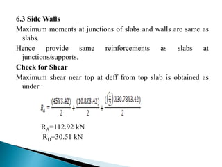
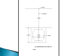
- The box culvert dimensions are 3m x 3m with a total cushion height of 5m above the top slab.
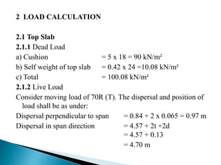
- Load calculations are presented for dead loads, live loads, earth pressures, and base pressure. Moments are then calculated.
- Distribution factors and moment distribution are determined for the fixed end moments on the top and bottom slabs and walls.
- The box culvert design is analyzed using STAAD Pro and drawings are created using AutoCAD.


![ PLAN OF BOX CULVERT
size of box culvert is 3mx3m.For box[1/3 x
3/0]and[1/3 x 3/5]
DESIGN OF BOX CULVERT
Load calculation
Moment calculation
Distribution factor
Moment distribution
Design of section](https://image.slidesharecdn.com/rccboxculvert-200209121543/85/Rcc-box-culvert-12-320.jpg)

![4.1 RCC BOX CULVERT, SPECIFICATION:
[1/3 x 3/0]
Design a box culvert size of [1/3 x 3/0] , except
the cushion which is 5.0 m total height above top
slab which is constructed in embankment which
come in the way of natural flow of storm water and
refer the given data below.
SPECIFICATION
Clear span = 3 m
Concrete grade M25 = 25 Mpa
Clear height = 3 m](https://image.slidesharecdn.com/rccboxculvert-200209121543/85/Rcc-box-culvert-15-320.jpg)


![Design a box culvert size of [1/3 x 3/5] ,except the
cushion which is 5.0 m total height above top slab which is
constructed in embankment which come in the way of
natural flow of storm water and refer the given data below.
SPECIFICATION
Clear span = 3 m
Concrete grade M25 = 25 Mpa
Clear height = 3 m
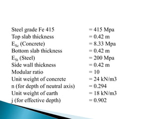
Steel grade Fe 415 = 415 Mpa
Top slab thickness = 0.42 m
ESc (Concrete) = 8.33 Mpa
Bottom slab thickness = 0.42 m](https://image.slidesharecdn.com/rccboxculvert-200209121543/85/Rcc-box-culvert-48-320.jpg)


![6.1 Top Slab
Maximum moment support/mid span = 83.0 kN.m
Depth required =274 mm ,
provided =362mm
(420-50-8=362) is ok
Ast =1271mm²
CHECK FOR SHEAR
Shear force at d eff from face of wall113.80 kN
Shear stress =0.3144 N/mm²
Permissible shear stress =0.2623 N/mm²
% of steel =0.351
[Refer IRC : 21:2000 Table 12 B]](https://image.slidesharecdn.com/rccboxculvert-200209121543/85/Rcc-box-culvert-70-320.jpg)