SlideShare a Scribd company logo
Created with ClearCalcs.comSteel Beam (version 69) — Floor Bearer
Client: My Client Date: Sep 18, 2019
Author: Brooks Smith Job #: 1
Project: Webinar Subject: B1
References: AS4100-1998
Moment Demand  
Moment Capacity  
Governing Load Case for Moment 1.2G, 1.5Q 
Shear Demand  
Shear Capacity  
Governing Load Case for Shear 1.2G, 1.5Q 
Shear and Moment Interaction  
Bearing Demand  
Bearing Capacity  
Governing Load Case for Bearing 1.2G, 1.5Q 
Bending and Bearing Interaction  
Max Short-Term Deflection  
Governing Load Case for Short-Term
Deflection
G, Q_st 
Max Long-Term Deflection  
Governing Load Case for Long-Term
Deflection
G, Q_lt 
Max Imposed Load Deflection  
Graphed Load Case
 
M ​ =gov
∗ 18.6 kNm
33% ϕM ​ =gov 56.2 kNm
M ​ =LC
∗
V =∗ 14.9 kN
9% ϕV ​ =v 165 kN
V ​ =LC
∗
9% int ​ =MV 0.0904
R ​ =gov
∗ 14.9 kN
9% ϕR ​ =gov 170 kN
R ​ =LC
∗
0% int ​ =MR 0
88% δ ​ =s −8.82 mm
δ ​ =s,LC
64% δ ​ =l −6.43 mm
δ ​ =l,LC
80% δ ​ =Q −7.98 mm
(Q) Unfactored Load
Load Case: Q
Envelope
1.0 2.0 3.0 4.0 5.0
Shear(kN)
-15
-10
-5
0
5
10
15
Load Case: Q
Envelope
1.0 2.0 3.0 4.0 5.0
Moment(kNm)
0
5
10
15
Summary
1
Member Type
Beam Orientation / Loading Direction
Total Beam Length  
Deflection Limit Span Criterion
Span Type (Interior or Cantilever) Short-Term Service ( ) Long-Term Service ( ) Imposed Load Q ( )
300 300 300
Deflection Limit Absolute Criterion  
Maximum Spacing of Lateral Restraints  
Position of Supports from Left
Support Type Position ( ) Length of Bearing ( ) Restraint Type
Pinned 0 150 P: Partial (Lateral at Non-critical Flange + Partial Torsional)
Pinned 5000 150 P: Partial (Lateral at Non-critical Flange + Partial Torsional)
Maximum Interior Span  
Maximum Cantilever  
Distributed Loads
Label Load Width ( ) Permanent Load ( ) Imposed Load ( ) Start Location ( ) End Location ( )
Floor Load 2000 0.5 1.5 0 5000
Height of Loads Application
Include Self Weight
Self Weight  
Character of Imposed Load
Wind Class
Ultimate Free Stream Dynamic Pressure  
Serviceability Free Stream Dynamic
Pressure
 
Net Downward Pressure Coefficient  
Net Uplift Pressure Coefficient  
Short-Term LC: Q
Envelope
1.0 2.0 3.0 4.0 5.0
Deflection(mm)
-8
-6
-4
-2
0
Distance from Left of Beam (m)
0.0 1.0 2.0 3.0 4.0 5.0
Floor Load
3
0 5 m
3 kN/m
7.5 kN 7.5 kN
 
180 UB 22.2 - Gr.300PLUS
Major Axis / Loaded from Top
L = 5000 mm
D =lim
L/ L/ L/
Interior Spans
Δ ​ =max 10 mm
L ​ =L 600 mm
r =
mm mm
L ​ =maxspan 5000 mm
L ​ =maxcant 0 mm
 
w =
mm kPa kPa mm mm
Top Flange
Yes
SW = 0.218 kN/m
Floors: Offices
 
N1
q ​ =u 0.69 kPa
q ​ =s 0.41 kPa
C ​ =pt,down↓ 0
C ​ =pt,up↑ 0
Key Properties
Permanent & Imposed Loads (AS1170.1)
Wind and Other Loads (AS1170.x)
2
Wind Tributary/Load Width  
Other Distributed Loads
Label Load Type Start Magnitude ( ) End Magnitude ( ) Start Location ( ) End Location ( )
Downward Wind Wu,dn 0 0 0 5000
Uplift Wind Wu,up 0 0 0 5000
Service Wind Ws 0 0 0 5000
Overall Breadth  
Maximum Beam Depth  
Overall Depth  
Number of Webs  
Depth Between Flanges  
Thickness of Web  
Web Slenderness Factor  
Web Yield Stress
Breadth of Flange  
Thickness of Flange  
Flange Slenderness Factor  
Flange Yield Stress  
Ultimate Stress  
Gross Second Moment of Area  
Gross Elastic Section Modulus  
Gross Plastic Section Modulus  
Effective Section Modulus (per
manufacturer)
 
Modulus of Elasticity  
Gross Axial Stiffness  
Gross Member Stiffness  
Shear Modulus of Elasticity  
Character of Imposed Load Factors
Imposed Load Type Short-Term Factor Long-Term Factor Combination Factor Earthquake Factor
0.7 0.4 0.4 0.3
1 0.6 0.4 0.3
LW ​ =wind 450 mm
w ​ =other
kN/m kN/m mm mm
 
b = 90 mm
d ​ =max 500 mm
d = 179 mm
n ​ =w 1
d ​ =l 159 mm
t ​ =w 6 mm
d ​/t ​ =l w 26.5
f =y,w 320 MPa
b ​ =f 90 mm
t ​ =f 10 mm
b ​/t ​ =f1 f 4.2
f ​ =y,f 320 MPa
f ​ =u 440 MPa
I = 15300000 mm3
I ​ =perp 1220000 mm3
Z = 171000 mm3
S = 195000 mm3
Z ​ =e 195000 mm3
E = 200000 MPa
EA = 564000 kN ∗ mm/mm
EI = 3060 kNm2
G ​ =S 80000 MPa
 
CharQ =
Distributed
Concentrated
Member Properties
Load Case Analysis (AS1170.0)
3
Strength Load Cases
Load Case Total Load ( ) Shear ( ) Moment ( ) Max Reaction ( )
1.35G 8.22 -4.11 5.14 4.11
1.2G, 1.5Q 29.8 14.9 18.6 14.9
1.2G, 1.5Q_lt 16.3 8.15 10.2 8.15
1.2G, Wu_down, Q_comb 13.3 -6.65 8.32 6.65
0.9G, Wu_up 5.48 -2.74 3.42 2.74
G, Eu, Q_E 10.6 -5.29 6.62 5.29
1.2G, Su, Q_comb 13.3 -6.65 8.32 6.65
Short-term Service Load Cases
Load Case Total Load ( ) Deflection ( )
G, Ws 6.09 -3.24
G, Q_st 16.6 -8.82
G, Ws, Q_lt 12.1 -6.43
G, Es, Q_lt 12.1 -6.43
G, Ss, Q_lt 12.1 -6.43
Long-term Service Load Cases
Load Case Total Load ( ) Deflection ( )
G 6.09 -3.24
G, Q_lt 12.1 -6.43
G, Ss, Q_lt 12.1 -6.43
Unfactored Load
Load Type Total Load ( ) Shear ( ) Moment ( ) Max Reaction ( ) Short-Term Deflection ( )
G 6.09 -3.04 3.81 3.04 -3.24
Q_dist 15 7.5 9.37 7.5 -7.98
Shear Capacity Factor  
Nominal Shear Yield Capacity  
Shear Buckling Coefficient  
Nominal Shear Buckling Capacity  
Nominal Shear Capacity in Uniform
Stress Distribution
 
Nominal Shear Capacity  
Capacity Factor  
Flange Element Slenderness  
Flange Element Yield Slenderness Limit  
Flange Element Plastic Slenderness Limit  
Section Compactness in Bending Compact 
Effective Section Modulus  
Section Moment Capacity  
Maximum Flange Area Reduction By
Holes
 
kN kN kNm kN
kN mm
kN mm
 
kN kN kNm kN mm
 
ϕ = 0.9
V ​ =w 183 kN
α ​ =v 7.48
V ​ =b 183 kN
V ​ =u 183 kN
V ​ =v 183 kN
 
ϕ = 0.9
λ ​ =e,f 4.75
λ ​ =ey,f 14
λ ​ =ep,f 8
compact ​ =f
Z ​ =e 195000 kNm
M ​ =s 62.4 kNm
A ​ =f,holes 14.4 %
Unfactored Load Analysis (AS1170.0)
Shear Capacity (AS4100-1998, Section 5.11)
Moment Section Capacity (AS4100-1998, Cl 5.3)
4
Moment Modification Factor Calculation
Span Length ( ) Span Type Maximum Moment ( ) Q1 Moment ( ) Q2 Moment ( ) Q3 Moment ( ) M Mod. Factor
5000 Int 18.6 13.9 18.6 13.9 1.17
Slenderness Reduction Factor
Span Length
 ( )
Span
Type
Twist Restraint
Factor
Lateral Rotation
Restraint Factor
Load Height
Factor
Effective
Length ( )
Reference Buckling
Moment ( )
Slenderness
Reduction Factor
5000 PP 1.15 1 1.4 969 252 0.901
Nominal Moment Utilisation
Span Length
 ( )
Span
Type
Moment Demand
 ( )
Member Moment Capacity
 ( )
Factored Moment Capacity
 ( )
Moment
Utilisation
5000 PP 18.6 65.7 56.2 0.332
Consider Proportioning Method? Yes 
Flange Element Slenderness  
Flange Element Yield Slenderness Limit  
Compression Flange Effective Width  
Compression Flange Effective Area  
Flange Gross Area  
Minimum Flange Net Area  
Tension Flange Effective Area  
Minimum Flange Effective Area  
Distance Between Flange Centroids  
Moment Capacity of Flanges Alone  
Factored Moment Capacity of Flanges
Alone
 
Bending & Shear Capacity Per Support
Position
 ( )
Moment Demand
 ( )
Factored Section Moment
Capacity ( )
Shear Demand
 ( )
Shear Capacity Given Moment
Interaction ( )
Shear Capacity Given
Moment Utilisation
0 0 56.2 14.9 165 0.0904
5000 0 56.2 -14.9 165 0.0904
Capacity Factor  
Interior Bearing Criteria  
Flange Lateral Restraint
Member Section Constant for Web
Buckling
 
Form Factor for Web Buckling  
Member Slenderness Reduction Factor
for Web
Position ( ) Geometric Slenderness Factor Factor Factor Factor Factor Slenderness Reduction
0 133 150 12.9 156 0.466 0.743 0.273
5 133 150 12.9 156 0.466 0.743 0.273
 
α ​ =m
mm kNm kNm kNm kNm
α ​ =s
mm mm kNm
M ​ =table
mm kNm kNm kNm
 
PM ​ =flag
λ ​ =e 4.75
λ ​ =ey 14
b ​∣d ​ =fe e 90 mm
A ​ =fc 8100 mm2
A ​ =fg 900 mm2
A ​ =fn,min 770 mm2
A ​ =ft 900 mm2
A ​ =fm 900 mm2
d ​ =f 169 mm
M ​ =f 48.7 kNm
ϕM ​ =f 43.8 kNm
r =
mm kNm kNm kN kN
 
ϕ = 0.9
B ​ =d 105 mm
One Flange Only
α ​ =b 0.5
k ​ =f 1 mm
α ​ =c,table
mm
Moment Capacity (AS4100-1998, Cl 5.1 & 5.6.1-2)
Shear - Bending Moment Interaction (AS4100, Cl 5.12)
Bearing Capacity (AS4100, Cl 5.13)
5
Bearing Capacity Per Support
Position
 ( )
Interior Location?
 ( )
Reaction
 ( )
Bearing Yield
Capacity ( )
Bearing Buckling
Capacity ( )
Factored Bearing
Capacity ( )
Bearing Utilisation
 ( )
0 1 14.9 480 188 170 0.0879
5000 1 14.9 480 188 170 0.0879
Bending & Bearing Capacity Per Support
Position
 ( )
Reaction
 ( )
Factored Bearing
Capacity ( )
Governing Moment Demand
 ( )
Factored Moment Capacity
 ( )
Bending & Bearing
Utilisation
0 14.9 170 0 56.2 0
5000 14.9 170 0 56.2 0
Short-Term Deflection Per Span
Span Length ( ) Span Type Short-Term Deflection ( ) Short-term Deflection Limit ( ) Deflection Utilisation
5000 Int -8.82 10 0.882
Long-Term Deflection Per Span
Span Length ( ) Span Type Long-Term Deflection ( ) Long-term Deflection Limit ( ) Deflection Utilisation
5000 Int -6.43 10 0.643
Imposed Load Deflection Per Span
Span Length ( ) Span Type Imposed Load Deflection ( ) Imposed Load Deflection Limit ( ) Deflection Utilisation
5000 Int -7.98 10 0.798
Comments
Steel Beam Analysis and Design to AS4100-1998 (R2016). Assumes: (1) Beam is of uniform cross-section along its full
length, (2) Detailing requirements are checked separately, (3) Net areas are equal to the gross area with maximum
allowed holes.
R ​ =table
mm kN kN kN kN kN kN
 
r =
mm kN kN kNm kNm
 
D ​ =ST
mm mm mm
D ​ =LT
mm mm mm
D ​ =Q
mm mm mm
 
 
Bending & Bearing Capacity (AS4100, Cl 5.13.5)
Deflection Analysis
Comments
Assumptions
6
Created with ClearCalcs.comSteel Beam (version 69) — Floor Bearer
Client: My Client Date: Sep 18, 2019
Author: Brooks Smith Job #: 1
Project: Webinar Subject: B2
References: AS4100-1998
Moment Demand  
Moment Capacity  
Governing Load Case for Moment 1.2G, 1.5Q 
Shear Demand  
Shear Capacity  
Governing Load Case for Shear 1.2G, 1.5Q 
Shear and Moment Interaction  
Bearing Demand  
Bearing Capacity  
Governing Load Case for Bearing 1.2G, 1.5Q 
Bending and Bearing Interaction  
Max Short-Term Deflection  
Governing Load Case for Short-Term
Deflection
G, Q_st 
Max Long-Term Deflection  
Governing Load Case for Long-Term
Deflection
G, Q_lt 
Max Imposed Load Deflection  
Graphed Load Case
 
M ​ =gov
∗ −79.1 kNm
26% ϕM ​ =gov 300 kNm
M ​ =LC
∗
V =∗ −38 kN
8% ϕV ​ =v 500 kN
V ​ =LC
∗
8% int ​ =MV 0.0759
R ​ =gov
∗ 69.6 kN
61% ϕR ​ =gov 115 kN
R ​ =LC
∗
0% int ​ =MR 0
91% δ ​ =s −9.12 mm
δ ​ =s,LC
69% δ ​ =l −6.86 mm
δ ​ =l,LC
75% δ ​ =Q −7.54 mm
(Q) Unfactored Load
Load Case: Q
Envelope
5 10 15 20
Shear(kN)
-40
-20
0
20
Load Case: Q
Envelope
5 10 15 20
Moment(kNm)
-80
-60
-40
-20
0
20
40
Summary
7
Member Type
Beam Orientation / Loading Direction
Total Beam Length  
Deflection Limit Span Criterion
Span Type (Interior or Cantilever) Short-Term Service ( ) Long-Term Service ( ) Imposed Load Q ( )
300 300 300
150 150 150
Deflection Limit Absolute Criterion  
Maximum Spacing of Lateral Restraints  
Position of Supports from Left
Support Type Position ( ) Length of Bearing ( ) Restraint Type
Pinned 0 150 P: Partial (Lateral at Non-critical Flange + Partial Torsional)
Pinned 4000 150 L: Lateral at Critical Flange Only
Pinned 15000 150 P: Partial (Lateral at Non-critical Flange + Partial Torsional)
Maximum Interior Span  
Maximum Cantilever  
Distributed Loads
Label Load Width ( ) Permanent Load ( ) Imposed Load ( ) Start Location ( ) End Location ( )
Floor Load 2000 0.5 1.5 0 20000
Height of Loads Application
Include Self Weight
Self Weight  
Character of Imposed Load
Wind Class
Ultimate Free Stream Dynamic Pressure  
Serviceability Free Stream Dynamic
Pressure
 
Short-Term LC: Q
Envelope
5 10 15 20
Deflection(mm)
-8
-6
-4
-2
0
Distance from Left of Beam (m)
0 5 10 15 20
Floor Load
3
0 20 m
3 kN/m
0.719 kN 26.3 kN 33 kN
 
410 UB 53.7 - Gr.300PLUS
Major Axis / Loaded from Top
L = 20000 mm
D =lim
L/ L/ L/
Interior Spans
Cantilevers
Δ ​ =max 10 mm
L ​ =L 600 mm
r =
mm mm
L ​ =maxspan 11000 mm
L ​ =maxcant 5000 mm
 
w =
mm kPa kPa mm mm
Top Flange
Yes
SW = 0.527 kN/m
Floors: Offices
 
N1
q ​ =u 0.69 kPa
q ​ =s 0.41 kPa
Key Properties
Permanent & Imposed Loads (AS1170.1)
Wind and Other Loads (AS1170.x)
8
Net Downward Pressure Coefficient  
Net Uplift Pressure Coefficient  
Wind Tributary/Load Width  
Other Distributed Loads
Label Load Type Start Magnitude ( ) End Magnitude ( ) Start Location ( ) End Location ( )
Downward Wind Wu,dn 0 0 0 20000
Uplift Wind Wu,up 0 0 0 20000
Service Wind Ws 0 0 0 20000
Overall Breadth  
Maximum Beam Depth  
Overall Depth  
Number of Webs  
Depth Between Flanges  
Thickness of Web
Web Slenderness Factor  
Web Yield Stress  
Breadth of Flange  
Thickness of Flange  
Flange Slenderness Factor  
Flange Yield Stress  
Ultimate Stress  
Gross Second Moment of Area  
Gross Elastic Section Modulus  
Gross Plastic Section Modulus  
Effective Section Modulus (per
manufacturer)
 
Modulus of Elasticity  
Gross Axial Stiffness  
Gross Member Stiffness  
Shear Modulus of Elasticity  
Character of Imposed Load Factors
Imposed Load Type Short-Term Factor Long-Term Factor Combination Factor Earthquake Factor
0.7 0.4 0.4 0.3
1 0.6 0.4 0.3
C ​ =pt,down↓ 0
C ​ =pt,up↑ 0
LW ​ =wind 450 mm
w ​ =other
kN/m kN/m mm mm
 
b = 178 mm
d ​ =max 500 mm
d = 403 mm
n ​ =w 1
d ​ =l 381 mm
t =w 7.6 mm
d ​/t ​ =l w 50.1
f ​ =y,w 320 MPa
b ​ =f 178 mm
t ​ =f 10.9 mm
b ​/t ​ =f1 f 7.82
f ​ =y,f 320 MPa
f ​ =u 440 MPa
I = 188000000 mm3
I ​ =perp 10300000 mm3
Z = 933000 mm3
S = 1060000 mm3
Z ​ =e 1060000 mm3
E = 200000 MPa
EA = 1380000 kN ∗ mm/mm
EI = 37600 kNm2
G ​ =S 80000 MPa
 
CharQ =
Distributed
Concentrated
Member Properties
Load Case Analysis (AS1170.0)
9
Strength Load Cases
Load Case Total Load ( ) Shear ( ) Moment ( ) Max Reaction ( )
1.35G 41.2 -12.4 -25.8 22.7
1.2G, 1.5Q 127 -38 -79.1 69.6
1.2G, 1.5Q_lt 72.6 -21.8 -45.4 39.9
1.2G, Wu_down, Q_comb 60.6 -18.2 -37.9 33.3
0.9G, Wu_up 27.5 -8.24 -17.2 15.1
G, Eu, Q_E 48.5 -14.6 -30.3 26.7
1.2G, Su, Q_comb 60.6 -18.2 -37.9 33.3
Short-term Service Load Cases
Load Case Total Load ( ) Deflection ( )
G, Ws 30.5 -3.84
G, Q_st 72.5 -9.12
G, Ws, Q_lt 54.5 -6.86
G, Es, Q_lt 54.5 -6.86
G, Ss, Q_lt 54.5 -6.86
Long-term Service Load Cases
Load Case Total Load ( ) Deflection ( )
G 30.5 -3.84
G, Q_lt 54.5 -6.86
G, Ss, Q_lt 54.5 -6.86
Unfactored Load
Load Type Total Load ( ) Shear ( ) Moment ( ) Max Reaction ( ) Short-Term Deflection ( )
G 30.5 -9.15 -19.1 16.8 -3.84
Q_dist 60 -18 -37.5 33 -7.54
Shear Capacity Factor  
Nominal Shear Yield Capacity  
Shear Buckling Coefficient  
Nominal Shear Buckling Capacity  
Nominal Shear Capacity in Uniform
Stress Distribution
 
Nominal Shear Capacity  
Capacity Factor  
Flange Element Slenderness  
Flange Element Yield Slenderness Limit  
Flange Element Plastic Slenderness Limit  
Section Compactness in Bending Non-compact 
Effective Section Modulus  
Section Moment Capacity  
Maximum Flange Area Reduction By
Holes
 
kN kN kNm kN
kN mm
kN mm
 
kN kN kNm kN mm
 
ϕ = 0.9
V ​ =w 556 kN
α ​ =v 2.09
V ​ =b 556 kN
V ​ =u 556 kN
V ​ =v 556 kN
 
ϕ = 0.9
λ ​ =e,f 8.85
λ ​ =ey,f 14
λ ​ =ep,f 8
compact ​ =f
Z ​ =e 1040000 kNm
M ​ =s 333 kNm
A ​ =f,holes 14.4 %
Unfactored Load Analysis (AS1170.0)
Shear Capacity (AS4100-1998, Section 5.11)
Moment Section Capacity (AS4100-1998, Cl 5.3)
10
Moment Modification Factor Calculation
Span Length ( ) Span Type Maximum Moment ( ) Q1 Moment ( ) Q2 Moment ( ) Q3 Moment ( ) M Mod. Factor
4000 Int -44.6 -1.63 -9.72 -24 2.5
11000 Int -79.1 17.8 34.1 2 2.5
5000 Cant -79.1 -45.6 -20.6 -5.23 1.25
Slenderness Reduction Factor
Span Length
 ( )
Span
Type
Twist Restraint
Factor
Lateral Rotation
Restraint Factor
Load Height
Factor
Effective
Length ( )
Reference Buckling
Moment ( )
Slenderness
Reduction Factor
4000 PL 1.47 1 1.4 1230 2660 0.967
11000 PL 1.47 1 1.4 1230 2660 0.967
5000 PP 1.23 1 1.4 1040 3750 0.987
Nominal Moment Utilisation
Span Length
 ( )
Span
Type
Moment Demand
 ( )
Member Moment Capacity
 ( )
Factored Moment Capacity
 ( )
Moment
Utilisation
4000 PL -44.6 806 300 0.149
11000 PL -79.1 806 300 0.264
5000 PP -79.1 411 300 0.264
Consider Proportioning Method? Yes 
Flange Element Slenderness  
Flange Element Yield Slenderness Limit  
Compression Flange Effective Width  
Compression Flange Effective Area  
Flange Gross Area  
Minimum Flange Net Area  
Tension Flange Effective Area  
Minimum Flange Effective Area  
Distance Between Flange Centroids  
Moment Capacity of Flanges Alone  
Factored Moment Capacity of Flanges
Alone
 
Bending & Shear Capacity Per Support
Position
 ( )
Moment Demand
 ( )
Factored Section Moment
Capacity ( )
Shear Demand
 ( )
Shear Capacity Given Moment
Interaction ( )
Shear Capacity Given
Moment Utilisation
0 0 300 1.52 500 0.00303
4000 -44.6 300 31.7 500 0.0633
15000 -79.1 300 -38 500 0.0759
Capacity Factor  
Interior Bearing Criteria  
Flange Lateral Restraint
Member Section Constant for Web
Buckling
 
Form Factor for Web Buckling  
 
α ​ =m
mm kNm kNm kNm kNm
α ​ =s
mm mm kNm
M ​ =table
mm kNm kNm kNm
 
PM ​ =flag
λ ​ =e 8.85
λ ​ =ey 14
b ​∣d ​ =fe e 178 mm
A ​ =fc 31700 mm2
A ​ =fg 1940 mm2
A ​ =fn,min 1660 mm2
A ​ =ft 1940 mm2
A ​ =fm 1940 mm2
d ​ =f 392 mm
M ​ =f 243 kNm
ϕM ​ =f 219 kNm
r =
mm kNm kNm kN kN
 
ϕ = 0.9
B ​ =d 218 mm
One Flange Only
α ​ =b 0.5
k ​ =f 1 mm
Moment Capacity (AS4100-1998, Cl 5.1 & 5.6.1-2)
Shear - Bending Moment Interaction (AS4100, Cl 5.12)
Bearing Capacity (AS4100, Cl 5.13)
11
Member Slenderness Reduction Factor
for Web
Position ( ) Geometric Slenderness Factor Factor Factor Factor Factor Slenderness Reduction
0 251 284 7.26 287 0.892 0.593 0.0896
4 251 284 7.26 287 0.892 0.593 0.0896
15 251 284 7.26 287 0.892 0.593 0.0896
Bearing Capacity Per Support
Position
 ( )
Interior Location?
 ( )
Reaction
 ( )
Bearing Yield
Capacity ( )
Bearing Buckling
Capacity ( )
Factored Bearing
Capacity ( )
Bearing Utilisation
 ( )
0 1 1.52 622 128 115 0.0132
4000 1 55.5 622 128 115 0.483
15000 1 69.6 622 128 115 0.607
Bending & Bearing Capacity Per Support
Position
 ( )
Reaction
 ( )
Factored Bearing
Capacity ( )
Governing Moment Demand
 ( )
Factored Moment Capacity
 ( )
Bending & Bearing
Utilisation
0 1.52 115 0 300 0
4000 55.5 115 -44.6 300 0
15000 69.6 115 -79.1 300 0
Short-Term Deflection Per Span
Span Length ( ) Span Type Short-Term Deflection ( ) Short-term Deflection Limit ( ) Deflection Utilisation
4000 Int 0.358 10 0.0358
11000 Int -4.13 10 0.413
5000 Cant -9.12 10 0.912
Long-Term Deflection Per Span
Span Length ( ) Span Type Long-Term Deflection ( ) Long-term Deflection Limit ( ) Deflection Utilisation
4000 Int 0.269 10 0.0269
11000 Int -3.11 10 0.311
5000 Cant -6.86 10 0.686
Imposed Load Deflection Per Span
Span Length ( ) Span Type Imposed Load Deflection ( ) Imposed Load Deflection Limit ( ) Deflection Utilisation
4000 Int 0.296 10 0.0296
11000 Int -3.42 10 0.342
5000 Cant -7.54 10 0.754
Comments
Steel Beam Analysis and Design to AS4100-1998 (R2016). Assumes: (1) Beam is of uniform cross-section along its full
length, (2) Detailing requirements are checked separately, (3) Net areas are equal to the gross area with maximum
allowed holes.
α ​ =c,table
mm
R ​ =table
mm kN kN kN kN kN kN
 
r =
mm kN kN kNm kNm
 
D ​ =ST
mm mm mm
D ​ =LT
mm mm mm
D ​ =Q
mm mm mm
 
 
Bending & Bearing Capacity (AS4100, Cl 5.13.5)
Deflection Analysis
Comments
Assumptions
12

More Related Content

What's hot

Concrete bridge-design-to-bs5400
Concrete bridge-design-to-bs5400Concrete bridge-design-to-bs5400
Concrete bridge-design-to-bs5400
Abhilash Chandra Dey
 
CE 72.52 - Lecture 7 - Strut and Tie Models
CE 72.52 - Lecture 7 - Strut and Tie ModelsCE 72.52 - Lecture 7 - Strut and Tie Models
CE 72.52 - Lecture 7 - Strut and Tie Models
Fawad Najam
 
Padeye calculation example
Padeye calculation examplePadeye calculation example
Padeye calculation example
Jhon Keliat
 
ASCE/SEI 7-10
ASCE/SEI 7-10ASCE/SEI 7-10
ASCE/SEI 7-10
TheJamez
 
23-Design of Column Base Plates (Steel Structural Design & Prof. Shehab Mourad)
23-Design of Column Base Plates (Steel Structural Design & Prof. Shehab Mourad)23-Design of Column Base Plates (Steel Structural Design & Prof. Shehab Mourad)
23-Design of Column Base Plates (Steel Structural Design & Prof. Shehab Mourad)
Hossam Shafiq II
 
Rectangular beam design by WSD method (singly & doubly reinforcement)
Rectangular beam design by WSD method (singly & doubly reinforcement)Rectangular beam design by WSD method (singly & doubly reinforcement)
Rectangular beam design by WSD method (singly & doubly reinforcement)
Md. Shahadat Hossain
 
Wind Design to AS/NZ 1170.2 Webinar Slides - ClearCalcs
Wind Design to AS/NZ 1170.2 Webinar Slides - ClearCalcsWind Design to AS/NZ 1170.2 Webinar Slides - ClearCalcs
Wind Design to AS/NZ 1170.2 Webinar Slides - ClearCalcs
ClearCalcs
 
Designing a Concrete Beam Using the New AS3600:2018 - Webinar Slides - ClearC...
Designing a Concrete Beam Using the New AS3600:2018 - Webinar Slides - ClearC...Designing a Concrete Beam Using the New AS3600:2018 - Webinar Slides - ClearC...
Designing a Concrete Beam Using the New AS3600:2018 - Webinar Slides - ClearC...
ClearCalcs
 
Designing a Cold-Formed Steel Beam Using AISI S100-16
Designing a Cold-Formed Steel Beam Using AISI S100-16Designing a Cold-Formed Steel Beam Using AISI S100-16
Designing a Cold-Formed Steel Beam Using AISI S100-16
ClearCalcs
 
Development length
Development length Development length
Development length
Toe Myint Naing
 
Column Interaction Diagram construction
Column Interaction Diagram constructionColumn Interaction Diagram construction
Column Interaction Diagram construction
Pritesh Parmar
 
21-Design of Simple Shear Connections (Steel Structural Design & Prof. Shehab...
21-Design of Simple Shear Connections (Steel Structural Design & Prof. Shehab...21-Design of Simple Shear Connections (Steel Structural Design & Prof. Shehab...
21-Design of Simple Shear Connections (Steel Structural Design & Prof. Shehab...
Hossam Shafiq II
 
Doubly reinforced beam design
Doubly reinforced beam   designDoubly reinforced beam   design
Doubly reinforced beam design
Selvakumar Palanisamy
 
Timber Design to AS1720.1 (+Amdt 3, 2010) Webinar - ClearCalcs
Timber Design to AS1720.1 (+Amdt 3, 2010) Webinar - ClearCalcsTimber Design to AS1720.1 (+Amdt 3, 2010) Webinar - ClearCalcs
Timber Design to AS1720.1 (+Amdt 3, 2010) Webinar - ClearCalcs
ClearCalcs
 
Soil pressure in etabs
Soil pressure in etabsSoil pressure in etabs
Soil pressure in etabs
Jacob shah
 
Prestress loss due to friction & anchorage take up
Prestress loss due to friction & anchorage take upPrestress loss due to friction & anchorage take up
Prestress loss due to friction & anchorage take up
Ayaz Malik
 
Etabs (atkins)
Etabs (atkins)Etabs (atkins)
Etabs (atkins)
Albert deGuzman
 
Structural engineering ii
Structural engineering iiStructural engineering ii
Structural engineering ii
Shekh Muhsen Uddin Ahmed
 
Footfall vibration analysis
Footfall vibration analysisFootfall vibration analysis
Footfall vibration analysis
Konstantinos Vazouras
 

What's hot (20)

Concrete bridge-design-to-bs5400
Concrete bridge-design-to-bs5400Concrete bridge-design-to-bs5400
Concrete bridge-design-to-bs5400
 
CE 72.52 - Lecture 7 - Strut and Tie Models
CE 72.52 - Lecture 7 - Strut and Tie ModelsCE 72.52 - Lecture 7 - Strut and Tie Models
CE 72.52 - Lecture 7 - Strut and Tie Models
 
Padeye calculation example
Padeye calculation examplePadeye calculation example
Padeye calculation example
 
ASCE/SEI 7-10
ASCE/SEI 7-10ASCE/SEI 7-10
ASCE/SEI 7-10
 
23-Design of Column Base Plates (Steel Structural Design & Prof. Shehab Mourad)
23-Design of Column Base Plates (Steel Structural Design & Prof. Shehab Mourad)23-Design of Column Base Plates (Steel Structural Design & Prof. Shehab Mourad)
23-Design of Column Base Plates (Steel Structural Design & Prof. Shehab Mourad)
 
Rectangular beam design by WSD method (singly & doubly reinforcement)
Rectangular beam design by WSD method (singly & doubly reinforcement)Rectangular beam design by WSD method (singly & doubly reinforcement)
Rectangular beam design by WSD method (singly & doubly reinforcement)
 
Wind Design to AS/NZ 1170.2 Webinar Slides - ClearCalcs
Wind Design to AS/NZ 1170.2 Webinar Slides - ClearCalcsWind Design to AS/NZ 1170.2 Webinar Slides - ClearCalcs
Wind Design to AS/NZ 1170.2 Webinar Slides - ClearCalcs
 
Designing a Concrete Beam Using the New AS3600:2018 - Webinar Slides - ClearC...
Designing a Concrete Beam Using the New AS3600:2018 - Webinar Slides - ClearC...Designing a Concrete Beam Using the New AS3600:2018 - Webinar Slides - ClearC...
Designing a Concrete Beam Using the New AS3600:2018 - Webinar Slides - ClearC...
 
Designing a Cold-Formed Steel Beam Using AISI S100-16
Designing a Cold-Formed Steel Beam Using AISI S100-16Designing a Cold-Formed Steel Beam Using AISI S100-16
Designing a Cold-Formed Steel Beam Using AISI S100-16
 
Development length
Development length Development length
Development length
 
Column Interaction Diagram construction
Column Interaction Diagram constructionColumn Interaction Diagram construction
Column Interaction Diagram construction
 
21-Design of Simple Shear Connections (Steel Structural Design & Prof. Shehab...
21-Design of Simple Shear Connections (Steel Structural Design & Prof. Shehab...21-Design of Simple Shear Connections (Steel Structural Design & Prof. Shehab...
21-Design of Simple Shear Connections (Steel Structural Design & Prof. Shehab...
 
Wind_Load
Wind_LoadWind_Load
Wind_Load
 
Doubly reinforced beam design
Doubly reinforced beam   designDoubly reinforced beam   design
Doubly reinforced beam design
 
Timber Design to AS1720.1 (+Amdt 3, 2010) Webinar - ClearCalcs
Timber Design to AS1720.1 (+Amdt 3, 2010) Webinar - ClearCalcsTimber Design to AS1720.1 (+Amdt 3, 2010) Webinar - ClearCalcs
Timber Design to AS1720.1 (+Amdt 3, 2010) Webinar - ClearCalcs
 
Soil pressure in etabs
Soil pressure in etabsSoil pressure in etabs
Soil pressure in etabs
 
Prestress loss due to friction & anchorage take up
Prestress loss due to friction & anchorage take upPrestress loss due to friction & anchorage take up
Prestress loss due to friction & anchorage take up
 
Etabs (atkins)
Etabs (atkins)Etabs (atkins)
Etabs (atkins)
 
Structural engineering ii
Structural engineering iiStructural engineering ii
Structural engineering ii
 
Footfall vibration analysis
Footfall vibration analysisFootfall vibration analysis
Footfall vibration analysis
 

Similar to AS4100 Steel Design Webinar Worked Examples

PLASTIC BEAM in design of stell beam design
PLASTIC BEAM in design of stell beam designPLASTIC BEAM in design of stell beam design
PLASTIC BEAM in design of stell beam design
vijaykumar925207
 
gantry girders in india
gantry girders in indiagantry girders in india
gantry girders in india
IJCMESJOURNAL
 
MAIN CANOPY BAJAJ HR(22.09.2016)
MAIN CANOPY BAJAJ HR(22.09.2016)MAIN CANOPY BAJAJ HR(22.09.2016)
MAIN CANOPY BAJAJ HR(22.09.2016)sufiyan shaikh
 
diff_bwt_is_800_101.ppt
diff_bwt_is_800_101.pptdiff_bwt_is_800_101.ppt
diff_bwt_is_800_101.ppt
M RAVI KUMAR
 
Guntry girder
Guntry girderGuntry girder
Guntry girder
kajol panchal
 
project ppt 2 pdf.pdf
project ppt 2 pdf.pdfproject ppt 2 pdf.pdf
project ppt 2 pdf.pdf
KarthikMasky
 
Gantry girder Analyse & design
Gantry girder Analyse & designGantry girder Analyse & design
Gantry girder Analyse & design
Ghawsudin
 
INDUSTRIAL BUILDING GANTRY GIRDER
INDUSTRIAL BUILDING  GANTRY GIRDERINDUSTRIAL BUILDING  GANTRY GIRDER
INDUSTRIAL BUILDING GANTRY GIRDER
Harsh Shani
 
3F TO 5F BEAM DESIGN SUMMARY.pdf
3F TO 5F BEAM DESIGN SUMMARY.pdf3F TO 5F BEAM DESIGN SUMMARY.pdf
3F TO 5F BEAM DESIGN SUMMARY.pdf
NicolasGeotina
 
3F TO 5F BEAM DESIGN SUMMARY.pdf
3F TO 5F BEAM DESIGN SUMMARY.pdf3F TO 5F BEAM DESIGN SUMMARY.pdf
3F TO 5F BEAM DESIGN SUMMARY.pdf
NicolasGeotina
 
unit-3.ppt
unit-3.pptunit-3.ppt
unit-3.ppt
sabishanu
 
DESIGN OF DECK SLAB AND GIRDERS- BRIDGE ENGINEERING
DESIGN OF DECK SLAB AND GIRDERS- BRIDGE ENGINEERINGDESIGN OF DECK SLAB AND GIRDERS- BRIDGE ENGINEERING
DESIGN OF DECK SLAB AND GIRDERS- BRIDGE ENGINEERING
LiyaWilson4
 
74CD7287-9848-426D-966F-ADE2BF37611C.ppt
74CD7287-9848-426D-966F-ADE2BF37611C.ppt74CD7287-9848-426D-966F-ADE2BF37611C.ppt
74CD7287-9848-426D-966F-ADE2BF37611C.ppt
GEOMScGroup2016
 
96729556 hoja-de-calculo-para-zapatas
96729556 hoja-de-calculo-para-zapatas96729556 hoja-de-calculo-para-zapatas
96729556 hoja-de-calculo-para-zapatas
Walther Castro
 
Presentation_Abdul Aziz Zantout_UP706051
Presentation_Abdul Aziz Zantout_UP706051Presentation_Abdul Aziz Zantout_UP706051
Presentation_Abdul Aziz Zantout_UP706051Abdul Aziz Zantout
 
Ref F2F Week 4 - Solution_unlocked.pdf
Ref F2F Week 4 - Solution_unlocked.pdfRef F2F Week 4 - Solution_unlocked.pdf
Ref F2F Week 4 - Solution_unlocked.pdf
Robin Arthur Flores
 
Ship design project & presentation 3
Ship design project &  presentation 3Ship design project &  presentation 3
Ship design project & presentation 3
Kifayath Chowdhury
 
IRJET- Planning, Analysis and Designing of Cantilever Residential Building
IRJET- Planning, Analysis and Designing of Cantilever Residential BuildingIRJET- Planning, Analysis and Designing of Cantilever Residential Building
IRJET- Planning, Analysis and Designing of Cantilever Residential Building
IRJET Journal
 
Bridge loading
Bridge loadingBridge loading
Bridge loading
kapilpant12
 
Construction Aspects of Rigid Pavements.ppt
Construction Aspects of Rigid Pavements.pptConstruction Aspects of Rigid Pavements.ppt
Construction Aspects of Rigid Pavements.ppt
bala506586
 

Similar to AS4100 Steel Design Webinar Worked Examples (20)

PLASTIC BEAM in design of stell beam design
PLASTIC BEAM in design of stell beam designPLASTIC BEAM in design of stell beam design
PLASTIC BEAM in design of stell beam design
 
gantry girders in india
gantry girders in indiagantry girders in india
gantry girders in india
 
MAIN CANOPY BAJAJ HR(22.09.2016)
MAIN CANOPY BAJAJ HR(22.09.2016)MAIN CANOPY BAJAJ HR(22.09.2016)
MAIN CANOPY BAJAJ HR(22.09.2016)
 
diff_bwt_is_800_101.ppt
diff_bwt_is_800_101.pptdiff_bwt_is_800_101.ppt
diff_bwt_is_800_101.ppt
 
Guntry girder
Guntry girderGuntry girder
Guntry girder
 
project ppt 2 pdf.pdf
project ppt 2 pdf.pdfproject ppt 2 pdf.pdf
project ppt 2 pdf.pdf
 
Gantry girder Analyse & design
Gantry girder Analyse & designGantry girder Analyse & design
Gantry girder Analyse & design
 
INDUSTRIAL BUILDING GANTRY GIRDER
INDUSTRIAL BUILDING  GANTRY GIRDERINDUSTRIAL BUILDING  GANTRY GIRDER
INDUSTRIAL BUILDING GANTRY GIRDER
 
3F TO 5F BEAM DESIGN SUMMARY.pdf
3F TO 5F BEAM DESIGN SUMMARY.pdf3F TO 5F BEAM DESIGN SUMMARY.pdf
3F TO 5F BEAM DESIGN SUMMARY.pdf
 
3F TO 5F BEAM DESIGN SUMMARY.pdf
3F TO 5F BEAM DESIGN SUMMARY.pdf3F TO 5F BEAM DESIGN SUMMARY.pdf
3F TO 5F BEAM DESIGN SUMMARY.pdf
 
unit-3.ppt
unit-3.pptunit-3.ppt
unit-3.ppt
 
DESIGN OF DECK SLAB AND GIRDERS- BRIDGE ENGINEERING
DESIGN OF DECK SLAB AND GIRDERS- BRIDGE ENGINEERINGDESIGN OF DECK SLAB AND GIRDERS- BRIDGE ENGINEERING
DESIGN OF DECK SLAB AND GIRDERS- BRIDGE ENGINEERING
 
74CD7287-9848-426D-966F-ADE2BF37611C.ppt
74CD7287-9848-426D-966F-ADE2BF37611C.ppt74CD7287-9848-426D-966F-ADE2BF37611C.ppt
74CD7287-9848-426D-966F-ADE2BF37611C.ppt
 
96729556 hoja-de-calculo-para-zapatas
96729556 hoja-de-calculo-para-zapatas96729556 hoja-de-calculo-para-zapatas
96729556 hoja-de-calculo-para-zapatas
 
Presentation_Abdul Aziz Zantout_UP706051
Presentation_Abdul Aziz Zantout_UP706051Presentation_Abdul Aziz Zantout_UP706051
Presentation_Abdul Aziz Zantout_UP706051
 
Ref F2F Week 4 - Solution_unlocked.pdf
Ref F2F Week 4 - Solution_unlocked.pdfRef F2F Week 4 - Solution_unlocked.pdf
Ref F2F Week 4 - Solution_unlocked.pdf
 
Ship design project & presentation 3
Ship design project &  presentation 3Ship design project &  presentation 3
Ship design project & presentation 3
 
IRJET- Planning, Analysis and Designing of Cantilever Residential Building
IRJET- Planning, Analysis and Designing of Cantilever Residential BuildingIRJET- Planning, Analysis and Designing of Cantilever Residential Building
IRJET- Planning, Analysis and Designing of Cantilever Residential Building
 
Bridge loading
Bridge loadingBridge loading
Bridge loading
 
Construction Aspects of Rigid Pavements.ppt
Construction Aspects of Rigid Pavements.pptConstruction Aspects of Rigid Pavements.ppt
Construction Aspects of Rigid Pavements.ppt
 

Recently uploaded

Railway Signalling Principles Edition 3.pdf
Railway Signalling Principles Edition 3.pdfRailway Signalling Principles Edition 3.pdf
Railway Signalling Principles Edition 3.pdf
TeeVichai
 
6th International Conference on Machine Learning & Applications (CMLA 2024)
6th International Conference on Machine Learning & Applications (CMLA 2024)6th International Conference on Machine Learning & Applications (CMLA 2024)
6th International Conference on Machine Learning & Applications (CMLA 2024)
ClaraZara1
 
Nuclear Power Economics and Structuring 2024
Nuclear Power Economics and Structuring 2024Nuclear Power Economics and Structuring 2024
Nuclear Power Economics and Structuring 2024
Massimo Talia
 
weather web application report.pdf
weather web application report.pdfweather web application report.pdf
weather web application report.pdf
Pratik Pawar
 
一比一原版(IIT毕业证)伊利诺伊理工大学毕业证成绩单专业办理
一比一原版(IIT毕业证)伊利诺伊理工大学毕业证成绩单专业办理一比一原版(IIT毕业证)伊利诺伊理工大学毕业证成绩单专业办理
一比一原版(IIT毕业证)伊利诺伊理工大学毕业证成绩单专业办理
zwunae
 
Gen AI Study Jams _ For the GDSC Leads in India.pdf
Gen AI Study Jams _ For the GDSC Leads in India.pdfGen AI Study Jams _ For the GDSC Leads in India.pdf
Gen AI Study Jams _ For the GDSC Leads in India.pdf
gdsczhcet
 
NO1 Uk best vashikaran specialist in delhi vashikaran baba near me online vas...
NO1 Uk best vashikaran specialist in delhi vashikaran baba near me online vas...NO1 Uk best vashikaran specialist in delhi vashikaran baba near me online vas...
NO1 Uk best vashikaran specialist in delhi vashikaran baba near me online vas...
Amil Baba Dawood bangali
 
Tutorial for 16S rRNA Gene Analysis with QIIME2.pdf
Tutorial for 16S rRNA Gene Analysis with QIIME2.pdfTutorial for 16S rRNA Gene Analysis with QIIME2.pdf
Tutorial for 16S rRNA Gene Analysis with QIIME2.pdf
aqil azizi
 
Industrial Training at Shahjalal Fertilizer Company Limited (SFCL)
Industrial Training at Shahjalal Fertilizer Company Limited (SFCL)Industrial Training at Shahjalal Fertilizer Company Limited (SFCL)
Industrial Training at Shahjalal Fertilizer Company Limited (SFCL)
MdTanvirMahtab2
 
Heap Sort (SS).ppt FOR ENGINEERING GRADUATES, BCA, MCA, MTECH, BSC STUDENTS
Heap Sort (SS).ppt FOR ENGINEERING GRADUATES, BCA, MCA, MTECH, BSC STUDENTSHeap Sort (SS).ppt FOR ENGINEERING GRADUATES, BCA, MCA, MTECH, BSC STUDENTS
Heap Sort (SS).ppt FOR ENGINEERING GRADUATES, BCA, MCA, MTECH, BSC STUDENTS
Soumen Santra
 
Basic Industrial Engineering terms for apparel
Basic Industrial Engineering terms for apparelBasic Industrial Engineering terms for apparel
Basic Industrial Engineering terms for apparel
top1002
 
Planning Of Procurement o different goods and services
Planning Of Procurement o different goods and servicesPlanning Of Procurement o different goods and services
Planning Of Procurement o different goods and services
JoytuBarua2
 
CME397 Surface Engineering- Professional Elective
CME397 Surface Engineering- Professional ElectiveCME397 Surface Engineering- Professional Elective
CME397 Surface Engineering- Professional Elective
karthi keyan
 
Hybrid optimization of pumped hydro system and solar- Engr. Abdul-Azeez.pdf
Hybrid optimization of pumped hydro system and solar- Engr. Abdul-Azeez.pdfHybrid optimization of pumped hydro system and solar- Engr. Abdul-Azeez.pdf
Hybrid optimization of pumped hydro system and solar- Engr. Abdul-Azeez.pdf
fxintegritypublishin
 
Pile Foundation by Venkatesh Taduvai (Sub Geotechnical Engineering II)-conver...
Pile Foundation by Venkatesh Taduvai (Sub Geotechnical Engineering II)-conver...Pile Foundation by Venkatesh Taduvai (Sub Geotechnical Engineering II)-conver...
Pile Foundation by Venkatesh Taduvai (Sub Geotechnical Engineering II)-conver...
AJAYKUMARPUND1
 
English lab ppt no titlespecENG PPTt.pdf
English lab ppt no titlespecENG PPTt.pdfEnglish lab ppt no titlespecENG PPTt.pdf
English lab ppt no titlespecENG PPTt.pdf
BrazilAccount1
 
AP LAB PPT.pdf ap lab ppt no title specific
AP LAB PPT.pdf ap lab ppt no title specificAP LAB PPT.pdf ap lab ppt no title specific
AP LAB PPT.pdf ap lab ppt no title specific
BrazilAccount1
 
RAT: Retrieval Augmented Thoughts Elicit Context-Aware Reasoning in Long-Hori...
RAT: Retrieval Augmented Thoughts Elicit Context-Aware Reasoning in Long-Hori...RAT: Retrieval Augmented Thoughts Elicit Context-Aware Reasoning in Long-Hori...
RAT: Retrieval Augmented Thoughts Elicit Context-Aware Reasoning in Long-Hori...
thanhdowork
 
14 Template Contractual Notice - EOT Application
14 Template Contractual Notice - EOT Application14 Template Contractual Notice - EOT Application
14 Template Contractual Notice - EOT Application
SyedAbiiAzazi1
 
一比一原版(UofT毕业证)多伦多大学毕业证成绩单如何办理
一比一原版(UofT毕业证)多伦多大学毕业证成绩单如何办理一比一原版(UofT毕业证)多伦多大学毕业证成绩单如何办理
一比一原版(UofT毕业证)多伦多大学毕业证成绩单如何办理
ydteq
 

Recently uploaded (20)

Railway Signalling Principles Edition 3.pdf
Railway Signalling Principles Edition 3.pdfRailway Signalling Principles Edition 3.pdf
Railway Signalling Principles Edition 3.pdf
 
6th International Conference on Machine Learning & Applications (CMLA 2024)
6th International Conference on Machine Learning & Applications (CMLA 2024)6th International Conference on Machine Learning & Applications (CMLA 2024)
6th International Conference on Machine Learning & Applications (CMLA 2024)
 
Nuclear Power Economics and Structuring 2024
Nuclear Power Economics and Structuring 2024Nuclear Power Economics and Structuring 2024
Nuclear Power Economics and Structuring 2024
 
weather web application report.pdf
weather web application report.pdfweather web application report.pdf
weather web application report.pdf
 
一比一原版(IIT毕业证)伊利诺伊理工大学毕业证成绩单专业办理
一比一原版(IIT毕业证)伊利诺伊理工大学毕业证成绩单专业办理一比一原版(IIT毕业证)伊利诺伊理工大学毕业证成绩单专业办理
一比一原版(IIT毕业证)伊利诺伊理工大学毕业证成绩单专业办理
 
Gen AI Study Jams _ For the GDSC Leads in India.pdf
Gen AI Study Jams _ For the GDSC Leads in India.pdfGen AI Study Jams _ For the GDSC Leads in India.pdf
Gen AI Study Jams _ For the GDSC Leads in India.pdf
 
NO1 Uk best vashikaran specialist in delhi vashikaran baba near me online vas...
NO1 Uk best vashikaran specialist in delhi vashikaran baba near me online vas...NO1 Uk best vashikaran specialist in delhi vashikaran baba near me online vas...
NO1 Uk best vashikaran specialist in delhi vashikaran baba near me online vas...
 
Tutorial for 16S rRNA Gene Analysis with QIIME2.pdf
Tutorial for 16S rRNA Gene Analysis with QIIME2.pdfTutorial for 16S rRNA Gene Analysis with QIIME2.pdf
Tutorial for 16S rRNA Gene Analysis with QIIME2.pdf
 
Industrial Training at Shahjalal Fertilizer Company Limited (SFCL)
Industrial Training at Shahjalal Fertilizer Company Limited (SFCL)Industrial Training at Shahjalal Fertilizer Company Limited (SFCL)
Industrial Training at Shahjalal Fertilizer Company Limited (SFCL)
 
Heap Sort (SS).ppt FOR ENGINEERING GRADUATES, BCA, MCA, MTECH, BSC STUDENTS
Heap Sort (SS).ppt FOR ENGINEERING GRADUATES, BCA, MCA, MTECH, BSC STUDENTSHeap Sort (SS).ppt FOR ENGINEERING GRADUATES, BCA, MCA, MTECH, BSC STUDENTS
Heap Sort (SS).ppt FOR ENGINEERING GRADUATES, BCA, MCA, MTECH, BSC STUDENTS
 
Basic Industrial Engineering terms for apparel
Basic Industrial Engineering terms for apparelBasic Industrial Engineering terms for apparel
Basic Industrial Engineering terms for apparel
 
Planning Of Procurement o different goods and services
Planning Of Procurement o different goods and servicesPlanning Of Procurement o different goods and services
Planning Of Procurement o different goods and services
 
CME397 Surface Engineering- Professional Elective
CME397 Surface Engineering- Professional ElectiveCME397 Surface Engineering- Professional Elective
CME397 Surface Engineering- Professional Elective
 
Hybrid optimization of pumped hydro system and solar- Engr. Abdul-Azeez.pdf
Hybrid optimization of pumped hydro system and solar- Engr. Abdul-Azeez.pdfHybrid optimization of pumped hydro system and solar- Engr. Abdul-Azeez.pdf
Hybrid optimization of pumped hydro system and solar- Engr. Abdul-Azeez.pdf
 
Pile Foundation by Venkatesh Taduvai (Sub Geotechnical Engineering II)-conver...
Pile Foundation by Venkatesh Taduvai (Sub Geotechnical Engineering II)-conver...Pile Foundation by Venkatesh Taduvai (Sub Geotechnical Engineering II)-conver...
Pile Foundation by Venkatesh Taduvai (Sub Geotechnical Engineering II)-conver...
 
English lab ppt no titlespecENG PPTt.pdf
English lab ppt no titlespecENG PPTt.pdfEnglish lab ppt no titlespecENG PPTt.pdf
English lab ppt no titlespecENG PPTt.pdf
 
AP LAB PPT.pdf ap lab ppt no title specific
AP LAB PPT.pdf ap lab ppt no title specificAP LAB PPT.pdf ap lab ppt no title specific
AP LAB PPT.pdf ap lab ppt no title specific
 
RAT: Retrieval Augmented Thoughts Elicit Context-Aware Reasoning in Long-Hori...
RAT: Retrieval Augmented Thoughts Elicit Context-Aware Reasoning in Long-Hori...RAT: Retrieval Augmented Thoughts Elicit Context-Aware Reasoning in Long-Hori...
RAT: Retrieval Augmented Thoughts Elicit Context-Aware Reasoning in Long-Hori...
 
14 Template Contractual Notice - EOT Application
14 Template Contractual Notice - EOT Application14 Template Contractual Notice - EOT Application
14 Template Contractual Notice - EOT Application
 
一比一原版(UofT毕业证)多伦多大学毕业证成绩单如何办理
一比一原版(UofT毕业证)多伦多大学毕业证成绩单如何办理一比一原版(UofT毕业证)多伦多大学毕业证成绩单如何办理
一比一原版(UofT毕业证)多伦多大学毕业证成绩单如何办理
 

AS4100 Steel Design Webinar Worked Examples

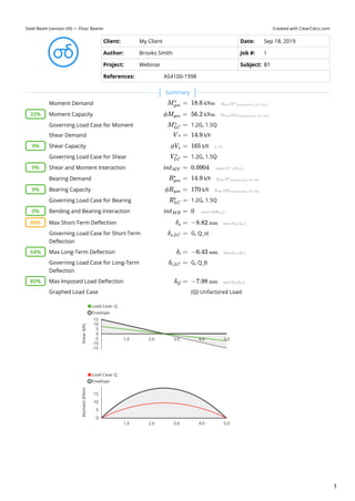
  • 1. Created with ClearCalcs.comSteel Beam (version 69) — Floor Bearer Client: My Client Date: Sep 18, 2019 Author: Brooks Smith Job #: 1 Project: Webinar Subject: B1 References: AS4100-1998 Moment Demand   Moment Capacity   Governing Load Case for Moment 1.2G, 1.5Q  Shear Demand   Shear Capacity   Governing Load Case for Shear 1.2G, 1.5Q  Shear and Moment Interaction   Bearing Demand   Bearing Capacity   Governing Load Case for Bearing 1.2G, 1.5Q  Bending and Bearing Interaction   Max Short-Term Deflection   Governing Load Case for Short-Term Deflection G, Q_st  Max Long-Term Deflection   Governing Load Case for Long-Term Deflection G, Q_lt  Max Imposed Load Deflection   Graphed Load Case   M ​ =gov ∗ 18.6 kNm 33% ϕM ​ =gov 56.2 kNm M ​ =LC ∗ V =∗ 14.9 kN 9% ϕV ​ =v 165 kN V ​ =LC ∗ 9% int ​ =MV 0.0904 R ​ =gov ∗ 14.9 kN 9% ϕR ​ =gov 170 kN R ​ =LC ∗ 0% int ​ =MR 0 88% δ ​ =s −8.82 mm δ ​ =s,LC 64% δ ​ =l −6.43 mm δ ​ =l,LC 80% δ ​ =Q −7.98 mm (Q) Unfactored Load Load Case: Q Envelope 1.0 2.0 3.0 4.0 5.0 Shear(kN) -15 -10 -5 0 5 10 15 Load Case: Q Envelope 1.0 2.0 3.0 4.0 5.0 Moment(kNm) 0 5 10 15 Summary 1
  • 2. Member Type Beam Orientation / Loading Direction Total Beam Length   Deflection Limit Span Criterion Span Type (Interior or Cantilever) Short-Term Service ( ) Long-Term Service ( ) Imposed Load Q ( ) 300 300 300 Deflection Limit Absolute Criterion   Maximum Spacing of Lateral Restraints   Position of Supports from Left Support Type Position ( ) Length of Bearing ( ) Restraint Type Pinned 0 150 P: Partial (Lateral at Non-critical Flange + Partial Torsional) Pinned 5000 150 P: Partial (Lateral at Non-critical Flange + Partial Torsional) Maximum Interior Span   Maximum Cantilever   Distributed Loads Label Load Width ( ) Permanent Load ( ) Imposed Load ( ) Start Location ( ) End Location ( ) Floor Load 2000 0.5 1.5 0 5000 Height of Loads Application Include Self Weight Self Weight   Character of Imposed Load Wind Class Ultimate Free Stream Dynamic Pressure   Serviceability Free Stream Dynamic Pressure   Net Downward Pressure Coefficient   Net Uplift Pressure Coefficient   Short-Term LC: Q Envelope 1.0 2.0 3.0 4.0 5.0 Deflection(mm) -8 -6 -4 -2 0 Distance from Left of Beam (m) 0.0 1.0 2.0 3.0 4.0 5.0 Floor Load 3 0 5 m 3 kN/m 7.5 kN 7.5 kN   180 UB 22.2 - Gr.300PLUS Major Axis / Loaded from Top L = 5000 mm D =lim L/ L/ L/ Interior Spans Δ ​ =max 10 mm L ​ =L 600 mm r = mm mm L ​ =maxspan 5000 mm L ​ =maxcant 0 mm   w = mm kPa kPa mm mm Top Flange Yes SW = 0.218 kN/m Floors: Offices   N1 q ​ =u 0.69 kPa q ​ =s 0.41 kPa C ​ =pt,down↓ 0 C ​ =pt,up↑ 0 Key Properties Permanent & Imposed Loads (AS1170.1) Wind and Other Loads (AS1170.x) 2
  • 3. Wind Tributary/Load Width   Other Distributed Loads Label Load Type Start Magnitude ( ) End Magnitude ( ) Start Location ( ) End Location ( ) Downward Wind Wu,dn 0 0 0 5000 Uplift Wind Wu,up 0 0 0 5000 Service Wind Ws 0 0 0 5000 Overall Breadth   Maximum Beam Depth   Overall Depth   Number of Webs   Depth Between Flanges   Thickness of Web   Web Slenderness Factor   Web Yield Stress Breadth of Flange   Thickness of Flange   Flange Slenderness Factor   Flange Yield Stress   Ultimate Stress   Gross Second Moment of Area   Gross Second Moment of Area   Gross Elastic Section Modulus   Gross Plastic Section Modulus   Effective Section Modulus (per manufacturer)   Modulus of Elasticity   Gross Axial Stiffness   Gross Member Stiffness   Shear Modulus of Elasticity   Character of Imposed Load Factors Imposed Load Type Short-Term Factor Long-Term Factor Combination Factor Earthquake Factor 0.7 0.4 0.4 0.3 1 0.6 0.4 0.3 LW ​ =wind 450 mm w ​ =other kN/m kN/m mm mm   b = 90 mm d ​ =max 500 mm d = 179 mm n ​ =w 1 d ​ =l 159 mm t ​ =w 6 mm d ​/t ​ =l w 26.5 f =y,w 320 MPa b ​ =f 90 mm t ​ =f 10 mm b ​/t ​ =f1 f 4.2 f ​ =y,f 320 MPa f ​ =u 440 MPa I = 15300000 mm3 I ​ =perp 1220000 mm3 Z = 171000 mm3 S = 195000 mm3 Z ​ =e 195000 mm3 E = 200000 MPa EA = 564000 kN ∗ mm/mm EI = 3060 kNm2 G ​ =S 80000 MPa   CharQ = Distributed Concentrated Member Properties Load Case Analysis (AS1170.0) 3
  • 4. Strength Load Cases Load Case Total Load ( ) Shear ( ) Moment ( ) Max Reaction ( ) 1.35G 8.22 -4.11 5.14 4.11 1.2G, 1.5Q 29.8 14.9 18.6 14.9 1.2G, 1.5Q_lt 16.3 8.15 10.2 8.15 1.2G, Wu_down, Q_comb 13.3 -6.65 8.32 6.65 0.9G, Wu_up 5.48 -2.74 3.42 2.74 G, Eu, Q_E 10.6 -5.29 6.62 5.29 1.2G, Su, Q_comb 13.3 -6.65 8.32 6.65 Short-term Service Load Cases Load Case Total Load ( ) Deflection ( ) G, Ws 6.09 -3.24 G, Q_st 16.6 -8.82 G, Ws, Q_lt 12.1 -6.43 G, Es, Q_lt 12.1 -6.43 G, Ss, Q_lt 12.1 -6.43 Long-term Service Load Cases Load Case Total Load ( ) Deflection ( ) G 6.09 -3.24 G, Q_lt 12.1 -6.43 G, Ss, Q_lt 12.1 -6.43 Unfactored Load Load Type Total Load ( ) Shear ( ) Moment ( ) Max Reaction ( ) Short-Term Deflection ( ) G 6.09 -3.04 3.81 3.04 -3.24 Q_dist 15 7.5 9.37 7.5 -7.98 Shear Capacity Factor   Nominal Shear Yield Capacity   Shear Buckling Coefficient   Nominal Shear Buckling Capacity   Nominal Shear Capacity in Uniform Stress Distribution   Nominal Shear Capacity   Capacity Factor   Flange Element Slenderness   Flange Element Yield Slenderness Limit   Flange Element Plastic Slenderness Limit   Section Compactness in Bending Compact  Effective Section Modulus   Section Moment Capacity   Maximum Flange Area Reduction By Holes   kN kN kNm kN kN mm kN mm   kN kN kNm kN mm   ϕ = 0.9 V ​ =w 183 kN α ​ =v 7.48 V ​ =b 183 kN V ​ =u 183 kN V ​ =v 183 kN   ϕ = 0.9 λ ​ =e,f 4.75 λ ​ =ey,f 14 λ ​ =ep,f 8 compact ​ =f Z ​ =e 195000 kNm M ​ =s 62.4 kNm A ​ =f,holes 14.4 % Unfactored Load Analysis (AS1170.0) Shear Capacity (AS4100-1998, Section 5.11) Moment Section Capacity (AS4100-1998, Cl 5.3) 4
  • 5. Moment Modification Factor Calculation Span Length ( ) Span Type Maximum Moment ( ) Q1 Moment ( ) Q2 Moment ( ) Q3 Moment ( ) M Mod. Factor 5000 Int 18.6 13.9 18.6 13.9 1.17 Slenderness Reduction Factor Span Length  ( ) Span Type Twist Restraint Factor Lateral Rotation Restraint Factor Load Height Factor Effective Length ( ) Reference Buckling Moment ( ) Slenderness Reduction Factor 5000 PP 1.15 1 1.4 969 252 0.901 Nominal Moment Utilisation Span Length  ( ) Span Type Moment Demand  ( ) Member Moment Capacity  ( ) Factored Moment Capacity  ( ) Moment Utilisation 5000 PP 18.6 65.7 56.2 0.332 Consider Proportioning Method? Yes  Flange Element Slenderness   Flange Element Yield Slenderness Limit   Compression Flange Effective Width   Compression Flange Effective Area   Flange Gross Area   Minimum Flange Net Area   Tension Flange Effective Area   Minimum Flange Effective Area   Distance Between Flange Centroids   Moment Capacity of Flanges Alone   Factored Moment Capacity of Flanges Alone   Bending & Shear Capacity Per Support Position  ( ) Moment Demand  ( ) Factored Section Moment Capacity ( ) Shear Demand  ( ) Shear Capacity Given Moment Interaction ( ) Shear Capacity Given Moment Utilisation 0 0 56.2 14.9 165 0.0904 5000 0 56.2 -14.9 165 0.0904 Capacity Factor   Interior Bearing Criteria   Flange Lateral Restraint Member Section Constant for Web Buckling   Form Factor for Web Buckling   Member Slenderness Reduction Factor for Web Position ( ) Geometric Slenderness Factor Factor Factor Factor Factor Slenderness Reduction 0 133 150 12.9 156 0.466 0.743 0.273 5 133 150 12.9 156 0.466 0.743 0.273   α ​ =m mm kNm kNm kNm kNm α ​ =s mm mm kNm M ​ =table mm kNm kNm kNm   PM ​ =flag λ ​ =e 4.75 λ ​ =ey 14 b ​∣d ​ =fe e 90 mm A ​ =fc 8100 mm2 A ​ =fg 900 mm2 A ​ =fn,min 770 mm2 A ​ =ft 900 mm2 A ​ =fm 900 mm2 d ​ =f 169 mm M ​ =f 48.7 kNm ϕM ​ =f 43.8 kNm r = mm kNm kNm kN kN   ϕ = 0.9 B ​ =d 105 mm One Flange Only α ​ =b 0.5 k ​ =f 1 mm α ​ =c,table mm Moment Capacity (AS4100-1998, Cl 5.1 & 5.6.1-2) Shear - Bending Moment Interaction (AS4100, Cl 5.12) Bearing Capacity (AS4100, Cl 5.13) 5
  • 6. Bearing Capacity Per Support Position  ( ) Interior Location?  ( ) Reaction  ( ) Bearing Yield Capacity ( ) Bearing Buckling Capacity ( ) Factored Bearing Capacity ( ) Bearing Utilisation  ( ) 0 1 14.9 480 188 170 0.0879 5000 1 14.9 480 188 170 0.0879 Bending & Bearing Capacity Per Support Position  ( ) Reaction  ( ) Factored Bearing Capacity ( ) Governing Moment Demand  ( ) Factored Moment Capacity  ( ) Bending & Bearing Utilisation 0 14.9 170 0 56.2 0 5000 14.9 170 0 56.2 0 Short-Term Deflection Per Span Span Length ( ) Span Type Short-Term Deflection ( ) Short-term Deflection Limit ( ) Deflection Utilisation 5000 Int -8.82 10 0.882 Long-Term Deflection Per Span Span Length ( ) Span Type Long-Term Deflection ( ) Long-term Deflection Limit ( ) Deflection Utilisation 5000 Int -6.43 10 0.643 Imposed Load Deflection Per Span Span Length ( ) Span Type Imposed Load Deflection ( ) Imposed Load Deflection Limit ( ) Deflection Utilisation 5000 Int -7.98 10 0.798 Comments Steel Beam Analysis and Design to AS4100-1998 (R2016). Assumes: (1) Beam is of uniform cross-section along its full length, (2) Detailing requirements are checked separately, (3) Net areas are equal to the gross area with maximum allowed holes. R ​ =table mm kN kN kN kN kN kN   r = mm kN kN kNm kNm   D ​ =ST mm mm mm D ​ =LT mm mm mm D ​ =Q mm mm mm     Bending & Bearing Capacity (AS4100, Cl 5.13.5) Deflection Analysis Comments Assumptions 6
  • 7. Created with ClearCalcs.comSteel Beam (version 69) — Floor Bearer Client: My Client Date: Sep 18, 2019 Author: Brooks Smith Job #: 1 Project: Webinar Subject: B2 References: AS4100-1998 Moment Demand   Moment Capacity   Governing Load Case for Moment 1.2G, 1.5Q  Shear Demand   Shear Capacity   Governing Load Case for Shear 1.2G, 1.5Q  Shear and Moment Interaction   Bearing Demand   Bearing Capacity   Governing Load Case for Bearing 1.2G, 1.5Q  Bending and Bearing Interaction   Max Short-Term Deflection   Governing Load Case for Short-Term Deflection G, Q_st  Max Long-Term Deflection   Governing Load Case for Long-Term Deflection G, Q_lt  Max Imposed Load Deflection   Graphed Load Case   M ​ =gov ∗ −79.1 kNm 26% ϕM ​ =gov 300 kNm M ​ =LC ∗ V =∗ −38 kN 8% ϕV ​ =v 500 kN V ​ =LC ∗ 8% int ​ =MV 0.0759 R ​ =gov ∗ 69.6 kN 61% ϕR ​ =gov 115 kN R ​ =LC ∗ 0% int ​ =MR 0 91% δ ​ =s −9.12 mm δ ​ =s,LC 69% δ ​ =l −6.86 mm δ ​ =l,LC 75% δ ​ =Q −7.54 mm (Q) Unfactored Load Load Case: Q Envelope 5 10 15 20 Shear(kN) -40 -20 0 20 Load Case: Q Envelope 5 10 15 20 Moment(kNm) -80 -60 -40 -20 0 20 40 Summary 7
  • 8. Member Type Beam Orientation / Loading Direction Total Beam Length   Deflection Limit Span Criterion Span Type (Interior or Cantilever) Short-Term Service ( ) Long-Term Service ( ) Imposed Load Q ( ) 300 300 300 150 150 150 Deflection Limit Absolute Criterion   Maximum Spacing of Lateral Restraints   Position of Supports from Left Support Type Position ( ) Length of Bearing ( ) Restraint Type Pinned 0 150 P: Partial (Lateral at Non-critical Flange + Partial Torsional) Pinned 4000 150 L: Lateral at Critical Flange Only Pinned 15000 150 P: Partial (Lateral at Non-critical Flange + Partial Torsional) Maximum Interior Span   Maximum Cantilever   Distributed Loads Label Load Width ( ) Permanent Load ( ) Imposed Load ( ) Start Location ( ) End Location ( ) Floor Load 2000 0.5 1.5 0 20000 Height of Loads Application Include Self Weight Self Weight   Character of Imposed Load Wind Class Ultimate Free Stream Dynamic Pressure   Serviceability Free Stream Dynamic Pressure   Short-Term LC: Q Envelope 5 10 15 20 Deflection(mm) -8 -6 -4 -2 0 Distance from Left of Beam (m) 0 5 10 15 20 Floor Load 3 0 20 m 3 kN/m 0.719 kN 26.3 kN 33 kN   410 UB 53.7 - Gr.300PLUS Major Axis / Loaded from Top L = 20000 mm D =lim L/ L/ L/ Interior Spans Cantilevers Δ ​ =max 10 mm L ​ =L 600 mm r = mm mm L ​ =maxspan 11000 mm L ​ =maxcant 5000 mm   w = mm kPa kPa mm mm Top Flange Yes SW = 0.527 kN/m Floors: Offices   N1 q ​ =u 0.69 kPa q ​ =s 0.41 kPa Key Properties Permanent & Imposed Loads (AS1170.1) Wind and Other Loads (AS1170.x) 8
  • 9. Net Downward Pressure Coefficient   Net Uplift Pressure Coefficient   Wind Tributary/Load Width   Other Distributed Loads Label Load Type Start Magnitude ( ) End Magnitude ( ) Start Location ( ) End Location ( ) Downward Wind Wu,dn 0 0 0 20000 Uplift Wind Wu,up 0 0 0 20000 Service Wind Ws 0 0 0 20000 Overall Breadth   Maximum Beam Depth   Overall Depth   Number of Webs   Depth Between Flanges   Thickness of Web Web Slenderness Factor   Web Yield Stress   Breadth of Flange   Thickness of Flange   Flange Slenderness Factor   Flange Yield Stress   Ultimate Stress   Gross Second Moment of Area   Gross Second Moment of Area   Gross Elastic Section Modulus   Gross Plastic Section Modulus   Effective Section Modulus (per manufacturer)   Modulus of Elasticity   Gross Axial Stiffness   Gross Member Stiffness   Shear Modulus of Elasticity   Character of Imposed Load Factors Imposed Load Type Short-Term Factor Long-Term Factor Combination Factor Earthquake Factor 0.7 0.4 0.4 0.3 1 0.6 0.4 0.3 C ​ =pt,down↓ 0 C ​ =pt,up↑ 0 LW ​ =wind 450 mm w ​ =other kN/m kN/m mm mm   b = 178 mm d ​ =max 500 mm d = 403 mm n ​ =w 1 d ​ =l 381 mm t =w 7.6 mm d ​/t ​ =l w 50.1 f ​ =y,w 320 MPa b ​ =f 178 mm t ​ =f 10.9 mm b ​/t ​ =f1 f 7.82 f ​ =y,f 320 MPa f ​ =u 440 MPa I = 188000000 mm3 I ​ =perp 10300000 mm3 Z = 933000 mm3 S = 1060000 mm3 Z ​ =e 1060000 mm3 E = 200000 MPa EA = 1380000 kN ∗ mm/mm EI = 37600 kNm2 G ​ =S 80000 MPa   CharQ = Distributed Concentrated Member Properties Load Case Analysis (AS1170.0) 9
  • 10. Strength Load Cases Load Case Total Load ( ) Shear ( ) Moment ( ) Max Reaction ( ) 1.35G 41.2 -12.4 -25.8 22.7 1.2G, 1.5Q 127 -38 -79.1 69.6 1.2G, 1.5Q_lt 72.6 -21.8 -45.4 39.9 1.2G, Wu_down, Q_comb 60.6 -18.2 -37.9 33.3 0.9G, Wu_up 27.5 -8.24 -17.2 15.1 G, Eu, Q_E 48.5 -14.6 -30.3 26.7 1.2G, Su, Q_comb 60.6 -18.2 -37.9 33.3 Short-term Service Load Cases Load Case Total Load ( ) Deflection ( ) G, Ws 30.5 -3.84 G, Q_st 72.5 -9.12 G, Ws, Q_lt 54.5 -6.86 G, Es, Q_lt 54.5 -6.86 G, Ss, Q_lt 54.5 -6.86 Long-term Service Load Cases Load Case Total Load ( ) Deflection ( ) G 30.5 -3.84 G, Q_lt 54.5 -6.86 G, Ss, Q_lt 54.5 -6.86 Unfactored Load Load Type Total Load ( ) Shear ( ) Moment ( ) Max Reaction ( ) Short-Term Deflection ( ) G 30.5 -9.15 -19.1 16.8 -3.84 Q_dist 60 -18 -37.5 33 -7.54 Shear Capacity Factor   Nominal Shear Yield Capacity   Shear Buckling Coefficient   Nominal Shear Buckling Capacity   Nominal Shear Capacity in Uniform Stress Distribution   Nominal Shear Capacity   Capacity Factor   Flange Element Slenderness   Flange Element Yield Slenderness Limit   Flange Element Plastic Slenderness Limit   Section Compactness in Bending Non-compact  Effective Section Modulus   Section Moment Capacity   Maximum Flange Area Reduction By Holes   kN kN kNm kN kN mm kN mm   kN kN kNm kN mm   ϕ = 0.9 V ​ =w 556 kN α ​ =v 2.09 V ​ =b 556 kN V ​ =u 556 kN V ​ =v 556 kN   ϕ = 0.9 λ ​ =e,f 8.85 λ ​ =ey,f 14 λ ​ =ep,f 8 compact ​ =f Z ​ =e 1040000 kNm M ​ =s 333 kNm A ​ =f,holes 14.4 % Unfactored Load Analysis (AS1170.0) Shear Capacity (AS4100-1998, Section 5.11) Moment Section Capacity (AS4100-1998, Cl 5.3) 10
  • 11. Moment Modification Factor Calculation Span Length ( ) Span Type Maximum Moment ( ) Q1 Moment ( ) Q2 Moment ( ) Q3 Moment ( ) M Mod. Factor 4000 Int -44.6 -1.63 -9.72 -24 2.5 11000 Int -79.1 17.8 34.1 2 2.5 5000 Cant -79.1 -45.6 -20.6 -5.23 1.25 Slenderness Reduction Factor Span Length  ( ) Span Type Twist Restraint Factor Lateral Rotation Restraint Factor Load Height Factor Effective Length ( ) Reference Buckling Moment ( ) Slenderness Reduction Factor 4000 PL 1.47 1 1.4 1230 2660 0.967 11000 PL 1.47 1 1.4 1230 2660 0.967 5000 PP 1.23 1 1.4 1040 3750 0.987 Nominal Moment Utilisation Span Length  ( ) Span Type Moment Demand  ( ) Member Moment Capacity  ( ) Factored Moment Capacity  ( ) Moment Utilisation 4000 PL -44.6 806 300 0.149 11000 PL -79.1 806 300 0.264 5000 PP -79.1 411 300 0.264 Consider Proportioning Method? Yes  Flange Element Slenderness   Flange Element Yield Slenderness Limit   Compression Flange Effective Width   Compression Flange Effective Area   Flange Gross Area   Minimum Flange Net Area   Tension Flange Effective Area   Minimum Flange Effective Area   Distance Between Flange Centroids   Moment Capacity of Flanges Alone   Factored Moment Capacity of Flanges Alone   Bending & Shear Capacity Per Support Position  ( ) Moment Demand  ( ) Factored Section Moment Capacity ( ) Shear Demand  ( ) Shear Capacity Given Moment Interaction ( ) Shear Capacity Given Moment Utilisation 0 0 300 1.52 500 0.00303 4000 -44.6 300 31.7 500 0.0633 15000 -79.1 300 -38 500 0.0759 Capacity Factor   Interior Bearing Criteria   Flange Lateral Restraint Member Section Constant for Web Buckling   Form Factor for Web Buckling     α ​ =m mm kNm kNm kNm kNm α ​ =s mm mm kNm M ​ =table mm kNm kNm kNm   PM ​ =flag λ ​ =e 8.85 λ ​ =ey 14 b ​∣d ​ =fe e 178 mm A ​ =fc 31700 mm2 A ​ =fg 1940 mm2 A ​ =fn,min 1660 mm2 A ​ =ft 1940 mm2 A ​ =fm 1940 mm2 d ​ =f 392 mm M ​ =f 243 kNm ϕM ​ =f 219 kNm r = mm kNm kNm kN kN   ϕ = 0.9 B ​ =d 218 mm One Flange Only α ​ =b 0.5 k ​ =f 1 mm Moment Capacity (AS4100-1998, Cl 5.1 & 5.6.1-2) Shear - Bending Moment Interaction (AS4100, Cl 5.12) Bearing Capacity (AS4100, Cl 5.13) 11
  • 12. Member Slenderness Reduction Factor for Web Position ( ) Geometric Slenderness Factor Factor Factor Factor Factor Slenderness Reduction 0 251 284 7.26 287 0.892 0.593 0.0896 4 251 284 7.26 287 0.892 0.593 0.0896 15 251 284 7.26 287 0.892 0.593 0.0896 Bearing Capacity Per Support Position  ( ) Interior Location?  ( ) Reaction  ( ) Bearing Yield Capacity ( ) Bearing Buckling Capacity ( ) Factored Bearing Capacity ( ) Bearing Utilisation  ( ) 0 1 1.52 622 128 115 0.0132 4000 1 55.5 622 128 115 0.483 15000 1 69.6 622 128 115 0.607 Bending & Bearing Capacity Per Support Position  ( ) Reaction  ( ) Factored Bearing Capacity ( ) Governing Moment Demand  ( ) Factored Moment Capacity  ( ) Bending & Bearing Utilisation 0 1.52 115 0 300 0 4000 55.5 115 -44.6 300 0 15000 69.6 115 -79.1 300 0 Short-Term Deflection Per Span Span Length ( ) Span Type Short-Term Deflection ( ) Short-term Deflection Limit ( ) Deflection Utilisation 4000 Int 0.358 10 0.0358 11000 Int -4.13 10 0.413 5000 Cant -9.12 10 0.912 Long-Term Deflection Per Span Span Length ( ) Span Type Long-Term Deflection ( ) Long-term Deflection Limit ( ) Deflection Utilisation 4000 Int 0.269 10 0.0269 11000 Int -3.11 10 0.311 5000 Cant -6.86 10 0.686 Imposed Load Deflection Per Span Span Length ( ) Span Type Imposed Load Deflection ( ) Imposed Load Deflection Limit ( ) Deflection Utilisation 4000 Int 0.296 10 0.0296 11000 Int -3.42 10 0.342 5000 Cant -7.54 10 0.754 Comments Steel Beam Analysis and Design to AS4100-1998 (R2016). Assumes: (1) Beam is of uniform cross-section along its full length, (2) Detailing requirements are checked separately, (3) Net areas are equal to the gross area with maximum allowed holes. α ​ =c,table mm R ​ =table mm kN kN kN kN kN kN   r = mm kN kN kNm kNm   D ​ =ST mm mm mm D ​ =LT mm mm mm D ​ =Q mm mm mm     Bending & Bearing Capacity (AS4100, Cl 5.13.5) Deflection Analysis Comments Assumptions 12