Download to read offline
![International Research Journal of Engineering and Technology (IRJET) e-ISSN: 2395-0056
Volume: 10 Issue: 06 | June 2023 www.irjet.net p-ISSN: 2395-0072
© 2023, IRJET | Impact Factor value: 8.226 | ISO 9001:2008 Certified Journal | Page 1102
IS CODE
A. Dead load Calculation :-
Self weight of GI Sheet = 171 KN/m²
Weight of purlin = 320 N/m² (200-400 N/m² )
Weight of bracing = 13 N/m² (12-15 N/m²)
Now,
a) self wt. of truss = ((L/ 3)+5) x 10
= ((16/ 3)+ 5) x 10
= 103.33 N/m2
b) Dead load per m² of plain area
=Wt. of GI Sheet + wt. of bracing + self wt.
of truss.
= 171 +13 + 103.33
= 287.33 N/m² of plain area
Panel length = 1.44m
α = 21.80α
Panel in length in plan = 1.44 x cos 21.80
= 1.33m
= 1.5 m
.’. Dead load on intermediate panel point
= [ Dead load per m² x Panel length in plan x
Spacing ] + [ Wt. of purlin x spacing of truss ]
= [281.33 X 1.5 X 4] + [320 X 4 ]
=3003.98
= [ Live load x Panel length in plan x spacing of
truss ]
= 0.48 x 1.44 x 4
= 2.76 KN
.’. Live load at end panel Length = ( 2.76/ 2 )
= 1.38 KN
= 3 m
.’. Dead load on end panel = (3/ 2)
= 1.5 KN
B. Live Load Calculation :-
As α = 21.80 > 10
for this truss access in not provided.
As per table 2, page no.14 of IS 875 part II 1987
.’. Live load per m2 = 0.75 – 0.002 (α – 10)
= 0.75 – 0.002 (21.80-10)
= 0.72 KN/m2 > 0.4 KN/m2
.’. Live load of roof truss = (2/ 3) x L.L per m2
= (2/ 3) x 0.72
= 0.48 KN/m2
.’. Live load on intermediate panel point](https://image.slidesharecdn.com/irjet-v10i6168-230711094520-acf4e6d9/85/COMPARISON-BETWEEN-VARIOUS-STEEL-SECTION-BY-USING-IS-CODE-AND-EURO-CODE-2-320.jpg)

![International Research Journal of Engineering and Technology (IRJET) e-ISSN: 2395-0056
Volume: 10 Issue: 06 | June 2023 www.irjet.net p-ISSN: 2395-0072
© 2023, IRJET | Impact Factor value: 8.226 | ISO 9001:2008 Certified Journal | Page 1104
.’. max Cpe = 0.8
.’. Max [Cpe - Cpi]
Cpe- Cpi = -0.8 - 0.7
= -1.5
Cpe- Cpi = -0.8 – (-0.7)
= -0.1
Max [Cpe - Cpi] = -1.5
9. Wind load on indiviual member
As per clause 6.2.1 Page No. 13 (IS: 875 Part III)
F = [Cpe - Cpi] A x Pz
Where,
A = exposed surface area.
A = slopping length x spacing of Truss
=8.61 X 6
A = 51.66 m
.’. F= [Cpe -Cpi] A x P₂
F = 1.5 x 51.66 x 835.8
F = 64.76 KN (uplift)
On one side of roof truss for intermediate panel points and
two end Panel point
.’. Wind load on intermediate Panel Point.
(W1/2) + W1 + W1 + W1 + W1 + W1 + (W1/ 2) = 64.76
6 W1 = 64.76
W1 = 10.79 KN
Wind load on end panel point
(W1/ 2) = (10.79/ 2) = 5.39 KN
EURO CODE
A. Dead load :-
Self-weight of long span aluminium roofing Sheet (0.55m
guage thickness) =0.019 KN/m2
Weight of ceiling cadopt 10 mm
Insulation fibre board = 0·077 KN/m²
Weight of services =0.1 KN/m²
Weight of purlin ( assume CH 150x75x18 kg/m)
=(8x4) / (1.33x4)
= 13 kg|m²
= 0.132 KN/m².
Self weigh of truss (assume) = 0.2 KN/m².
Total dead load (qv) = 0.536 KN/m²
The nodal dead load = 0.536x1.33x 4
=2.85 KN
.’. At end = 2.85 / 2
= 1.42 KN](https://image.slidesharecdn.com/irjet-v10i6168-230711094520-acf4e6d9/85/COMPARISON-BETWEEN-VARIOUS-STEEL-SECTION-BY-USING-IS-CODE-AND-EURO-CODE-4-320.jpg)

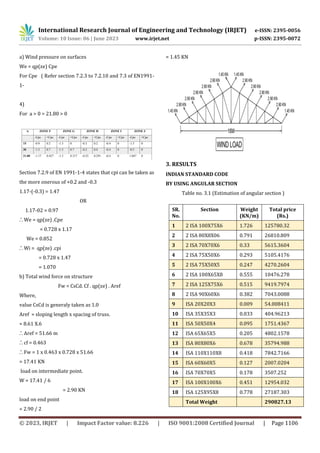


This document compares various steel sections for a roof truss design using the Indian Standard code and Eurocode. Load calculations are performed for dead load, live load, and wind load according to each code. The loads are then analyzed in STAAD Pro software. Various angular and tabular sections are estimated based on the codes. Finally, a cost comparison is done for the sections to determine the most economical option. The aim is to provide guidance on which section choice is most cost-effective.


