Wellhead and Christmas tree products are used to monitor well pressure, adjust oil/gas well flow and prevent the release of hazardous liquid and gas from entering into air or water
This is an academic lecture for Diploma in Engineering 7th Semester Mining and Mine Survey Technology. The Course related to this presentation is Well completion and testing
Well Control is very important in Petroleum Engineering and necessary for being able to avoid hazards and controlling them as much as possible. This presentation provides valuable notes, instructions, and information about Well Control.
Cosmetic shop management system project report.pdfKamal Acharya
Buying new cosmetic products is difficult. It can even be scary for those who have sensitive skin and are prone to skin trouble. The information needed to alleviate this problem is on the back of each product, but it's thought to interpret those ingredient lists unless you have a background in chemistry.
Instead of buying and hoping for the best, we can use data science to help us predict which products may be good fits for us. It includes various function programs to do the above mentioned tasks.
Data file handling has been effectively used in the program.
The automated cosmetic shop management system should deal with the automation of general workflow and administration process of the shop. The main processes of the system focus on customer's request where the system is able to search the most appropriate products and deliver it to the customers. It should help the employees to quickly identify the list of cosmetic product that have reached the minimum quantity and also keep a track of expired date for each cosmetic product. It should help the employees to find the rack number in which the product is placed.It is also Faster and more efficient way.
Student information management system project report ii.pdfKamal Acharya
Our project explains about the student management. This project mainly explains the various actions related to student details. This project shows some ease in adding, editing and deleting the student details. It also provides a less time consuming process for viewing, adding, editing and deleting the marks of the students.
Sachpazis:Terzaghi Bearing Capacity Estimation in simple terms with Calculati...Dr.Costas Sachpazis
Terzaghi's soil bearing capacity theory, developed by Karl Terzaghi, is a fundamental principle in geotechnical engineering used to determine the bearing capacity of shallow foundations. This theory provides a method to calculate the ultimate bearing capacity of soil, which is the maximum load per unit area that the soil can support without undergoing shear failure. The Calculation HTML Code included.
NO1 Uk best vashikaran specialist in delhi vashikaran baba near me online vas...Amil Baba Dawood bangali
Contact with Dawood Bhai Just call on +92322-6382012 and we'll help you. We'll solve all your problems within 12 to 24 hours and with 101% guarantee and with astrology systematic. If you want to take any personal or professional advice then also you can call us on +92322-6382012 , ONLINE LOVE PROBLEM & Other all types of Daily Life Problem's.Then CALL or WHATSAPP us on +92322-6382012 and Get all these problems solutions here by Amil Baba DAWOOD BANGALI
#vashikaranspecialist #astrologer #palmistry #amliyaat #taweez #manpasandshadi #horoscope #spiritual #lovelife #lovespell #marriagespell#aamilbabainpakistan #amilbabainkarachi #powerfullblackmagicspell #kalajadumantarspecialist #realamilbaba #AmilbabainPakistan #astrologerincanada #astrologerindubai #lovespellsmaster #kalajaduspecialist #lovespellsthatwork #aamilbabainlahore#blackmagicformarriage #aamilbaba #kalajadu #kalailam #taweez #wazifaexpert #jadumantar #vashikaranspecialist #astrologer #palmistry #amliyaat #taweez #manpasandshadi #horoscope #spiritual #lovelife #lovespell #marriagespell#aamilbabainpakistan #amilbabainkarachi #powerfullblackmagicspell #kalajadumantarspecialist #realamilbaba #AmilbabainPakistan #astrologerincanada #astrologerindubai #lovespellsmaster #kalajaduspecialist #lovespellsthatwork #aamilbabainlahore #blackmagicforlove #blackmagicformarriage #aamilbaba #kalajadu #kalailam #taweez #wazifaexpert #jadumantar #vashikaranspecialist #astrologer #palmistry #amliyaat #taweez #manpasandshadi #horoscope #spiritual #lovelife #lovespell #marriagespell#aamilbabainpakistan #amilbabainkarachi #powerfullblackmagicspell #kalajadumantarspecialist #realamilbaba #AmilbabainPakistan #astrologerincanada #astrologerindubai #lovespellsmaster #kalajaduspecialist #lovespellsthatwork #aamilbabainlahore #Amilbabainuk #amilbabainspain #amilbabaindubai #Amilbabainnorway #amilbabainkrachi #amilbabainlahore #amilbabaingujranwalan #amilbabainislamabad
Water scarcity is the lack of fresh water resources to meet the standard water demand. There are two type of water scarcity. One is physical. The other is economic water scarcity.
Immunizing Image Classifiers Against Localized Adversary Attacksgerogepatton
This paper addresses the vulnerability of deep learning models, particularly convolutional neural networks
(CNN)s, to adversarial attacks and presents a proactive training technique designed to counter them. We
introduce a novel volumization algorithm, which transforms 2D images into 3D volumetric representations.
When combined with 3D convolution and deep curriculum learning optimization (CLO), itsignificantly improves
the immunity of models against localized universal attacks by up to 40%. We evaluate our proposed approach
using contemporary CNN architectures and the modified Canadian Institute for Advanced Research (CIFAR-10
and CIFAR-100) and ImageNet Large Scale Visual Recognition Challenge (ILSVRC12) datasets, showcasing
accuracy improvements over previous techniques. The results indicate that the combination of the volumetric
input and curriculum learning holds significant promise for mitigating adversarial attacks without necessitating
adversary training.
CFD Simulation of By-pass Flow in a HRSG module by R&R Consult.pptxR&R Consult
CFD analysis is incredibly effective at solving mysteries and improving the performance of complex systems!
Here's a great example: At a large natural gas-fired power plant, where they use waste heat to generate steam and energy, they were puzzled that their boiler wasn't producing as much steam as expected.
R&R and Tetra Engineering Group Inc. were asked to solve the issue with reduced steam production.
An inspection had shown that a significant amount of hot flue gas was bypassing the boiler tubes, where the heat was supposed to be transferred.
R&R Consult conducted a CFD analysis, which revealed that 6.3% of the flue gas was bypassing the boiler tubes without transferring heat. The analysis also showed that the flue gas was instead being directed along the sides of the boiler and between the modules that were supposed to capture the heat. This was the cause of the reduced performance.
Based on our results, Tetra Engineering installed covering plates to reduce the bypass flow. This improved the boiler's performance and increased electricity production.
It is always satisfying when we can help solve complex challenges like this. Do your systems also need a check-up or optimization? Give us a call!
Work done in cooperation with James Malloy and David Moelling from Tetra Engineering.
More examples of our work https://www.r-r-consult.dk/en/cases-en/
Hierarchical Digital Twin of a Naval Power SystemKerry Sado
A hierarchical digital twin of a Naval DC power system has been developed and experimentally verified. Similar to other state-of-the-art digital twins, this technology creates a digital replica of the physical system executed in real-time or faster, which can modify hardware controls. However, its advantage stems from distributing computational efforts by utilizing a hierarchical structure composed of lower-level digital twin blocks and a higher-level system digital twin. Each digital twin block is associated with a physical subsystem of the hardware and communicates with a singular system digital twin, which creates a system-level response. By extracting information from each level of the hierarchy, power system controls of the hardware were reconfigured autonomously. This hierarchical digital twin development offers several advantages over other digital twins, particularly in the field of naval power systems. The hierarchical structure allows for greater computational efficiency and scalability while the ability to autonomously reconfigure hardware controls offers increased flexibility and responsiveness. The hierarchical decomposition and models utilized were well aligned with the physical twin, as indicated by the maximum deviations between the developed digital twin hierarchy and the hardware.
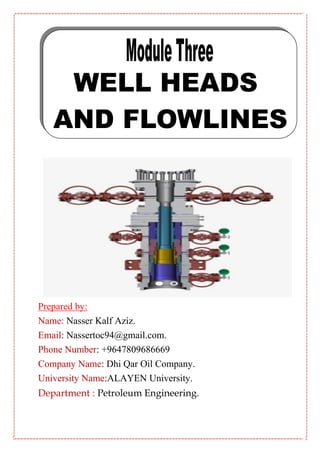
1. Prepared by:
Name: Nasser Kalf Aziz.
Email: Nassertoc94@gmail.com.
Phone Number: +9647809686669
Company Name: Dhi Qar Oil Company.
University Name:ALAYEN University.
Department : Petroleum Engineering.
2. 2
Introduction
Wellhead and Christmas tree products are used to monitor well pressure,
adjust oil/gas well flow and prevent the release of hazardous liquid
and gas from entering into air or water during drilling and oil & gas
production. They can be applicable for acidizing, fracturing, water
flooding and testing as well. Jereh wellhead and Christmas tree
products are designed in compliance with API 6A (20th edition) and
NACE MR0175.
WELL HEADS
Different Types of Well to be Found :
Each flowing wellhead, although differing in detail and exact configuration, is
made up of the following components:
1. Casing Head, supports the surface casing.
2. Tubing head, this supports the production tubing and is attached to
the top of the casing head with a flanged joint.
3. Christmas Tree, fixed to the top of the tubing head with a flanged
joint, it consists of the following:
a. Lower Master Valve. This valve is kept fully open and is used as
the emergency shut-in valve.
b. Upper Master Valve. This is used to open up or shut-in the well. In
order to reduce wear on this valve to an absolute minimum it is
always opened first when opening up a well and shut last when
shutting down a well. The upper master valve is equipped with a
pressure controlled actuator being held in position by a high/low
pressure pilot. The pilot receives impulses from downstream of
the adjustable choke valve. If the pilot registers a high or low
pressure the upper master valve will automatically shut, shutting
in the well.
c. Wing Valves. One or two wing valves may be fitted depending on
whether the Christmas tree has one flow outlet (a tee) or two flow
outlets (a cross). A wing valve is used to open up and shut off the
flow of crude oil to the production line. It is always opened after
the upper master valve and closed before it.
d. Swab Valve. Isolates the treetop adopter from the well. Only open
when carrying out wireline work.
3. 3
e. Treetop Adapter. Attached to the top of the Christmas tree is used
to locate the wireline equipment when carrying out downhole
maintenance work.
f. Tubing Pressure Gauge. Usually fitted to the treetop adaptor the
tubing pressure gauge measures pressure in the production
tubing.
g. Casing Pressure Gauge. Measures pressure in the tubing
annulus.
4. Adjustable Choke Valve. This is located downstream of the wing
valve, and controls the rate of flow of crude from the well.
Sweet crude oil flows from the Rutbah wells under natural pressure, to
the inlet manifold through flowlines.
8. 8
PRODUCING WELL EQUIPMENT
Wells can be completed with one or two strings. What follows describes the
equipment fitted to these wells.
STORM CHOKE
The storm choke is a safety valve see Figure 2.1 fitted inside the tubing at a
depth of 1000m. Its function is to close automatically if there is an abnormally
high flow of oil through the wellhead above. Once it has closed it will not re-
open automatically, but must be re-opened by the use of special wirline
equipment. This is a complicated and expensive operation which is carried out
by a trained wireline crew. The conditions which will close the storm choke
occur when there is a burst at the wellhead or in the flowline. Such a burst will
cause the oil to flow out of the well very rapidly, with an equally rapid drop in
pressure. It this rapid pressure drop which triggers the storm choke, in fact any
rapid pressure drop can trigger it , for instance, quick and careless opening of
wellhead valves by an operator. For this reason care and attention are
essential on all wellhead operations.
OPERATION
The principle of the storm choke is that it is cesigned to be normally open but
to close if there is a high differential pressure (d.p.) across it.
During normal flow the piston is held above the bottom seat but is not in
contact with the top seat. It is held between them by a balance between the
spring tension pulling down and the oil pushing up. Thus oil can flow.
If there is a sudden increase in flow at the wellhead because of a burst pipe or
a rapid valve opening, oil will flow away quickly causing a sudden pressure
drop above the choke. The oil pressure below will then immediately push the
piston against the seat and hold it there. Thus oil cannot flow.
To re-open a storm choke which has been closed by a high d.p., its upstream
and downstream pressures must be equalized. This can be done by
pressuring the tubing string from above or by using a wireline and equalizing
prong down the string .
There is a second type used in which the same conditions cause a flap to
close across the flow.
9. 9
Figure 2.1 : STORM CHOKE
Figure 2.2 : SINGLE STRING CHRISTMAS TREE
10. 01
LOWER MASTER VALVE
This is a manual gate valve fitted at the bottom of a Christmas tree as shown
in Figure 2.2 which should be operated as seldom as is possible; only for very
long periods of shutdown or for servicing of the next downstream valve. These
two instructions are necessary to prevent wear of the tubing master valve. If it
does wear then the well must be plugged before it can be serviced. To prevent
excessive wear of the valve it should never be in a partially open position
when the oil is flowing.
UPPER MASTER VALVE
This is a manual gate valve which is operated more often than the master
valve; e.g., for wireline operations, long shutdown and servicing of the next
downstream valve. When it is operated the next valve downstream should
always be closed. The tubing valve should never be in a partially open position
when the oil is flowing.
WING VALVE
This is a manual gate valve which is used for normal well closing-in opening-
up operations. It therefore gets the most wear. If it has been closed for some
time the operator should be aware that on its upstream side there will be full
static wellhead pressure, probably with a pocket of separated gas. To prevent
the storm choke from closing, the wing valve must be opened very slowly. If
there is gas its movement through the valve will have a distinctive sound. This
sound will change when the oil reaches the valve. The expanding gas may
cause a temporary frost at the valve and downstream from it. (See Gas Laws).
The wing valve should never be in a partially open position when the oil is
flowing.
CHOKE
These are regulators which permit the oil flow to line at fixed rates. The rates
are determined from studies of well performance made by the operations
engineering staff. There are three types:
The Multiple Orifice
The Rotary
Adjustable ( with changeable bean of tungsten alloy).
The Multiple Orifice Valve (Willis Choke )
This valve as shown in Figure 2.3 contains the choke and enables its opening
diameter to be adjusted without interrupting the flow from the well. The choke
consists of two porcelain discs (back disc and front disc) enclosed in a steel
seat. One disc is held stationary whilst the other is rotated to an intermediate
position to control flow. This choke is less resistant to erosion so is not used
on sandy wells.
11. 00
Figure 2.3 : WILLIS CHOKE
The Rotary Choke
This type of choke uses an indexing disc with six different size replaceable
beans to give fixed rates of flow. The beans are chosen to suit the productive
capacity of the well. One of the beans can be a blank in order to obtain a
positive shut-off of the well when necessary.
Adjustable Choke With Changeable Bean
This type choke is shown in Figure 2.4 and is similar in construction to a
needle valve. It contains two beans, the master bean and a changeable or
peroration bean. Further adjustment is made using a handwheel operated
stem which terminates in a needle valve.
SWAB VALVE
This is a manual gate valve which is opened to allow oil pressure through the
top adaptor for reading pressure or taking samples. It also allows the wireline
crew vertical access for operation inside the tubing string; e.g., work on the
storm choke, or plugging the tubing string.
SAFETY VALVES
These valves operate automatically to close-in the well when the flowine
pressure goes above or below set limits. Thus, it protects the flowline if the
wellhead pressure goes too high and protects the well if the flowline pressure
goes too low.
12. 02
There are four general types in use :
The Safomatic.
The Manumatic.
The Baker Submersible.
The Cameron Type FC.
They are described here in brief, full descriptions and illustrations are given in
the instrument section of this manual.
The Safomatic
This valve blocks the oil flow by releasing a steel ball into the flow stream. Oil
pressure moves the ball against a seat and holds it there until it is reset
manually. The flowline pressure is monitored internally by springs incorporated
inside the valve.
13. 03
The Manumatic
This valve uses a gate to block the oil flow. The gate is moved by a
pneumatically pressurized actuator controlled by pilots which are continuously
monitoring the flowline pressure. After a closure the gate will automatically re-
open if the flowline pressure returns to normal. A handwheel is incorporated
for manual operation.
The Christmas trees shown in Figure 2.6 are both fitted with Manumatic
valves.
The Baker Submersible
This is a get valve fitted to wellheads liable to flooding. Its operation is similar
to the Manumatic valve except that its actuator is hydraulically pressureised.
The Cameron Type FC
This valve uses a gate to block the oil flow. The gate is moved by a piston
hydraulically powered from the oil within the line. The power piston movement
is controlled by a pilot cylinder monitoring the flowline pressure. After a closure
the gate will automatically re-open if the flowline pressure returns to normal.
An Auto/Open switch is incorporated for manual opening.
CHECK VALVE
This prevents any reverse flow from the line into the well. It has a hinged flap
as illustrated in Figure 2.5 which lifts to permit normal flow, but closes to
prevent reverse flow. Although fitted to many older installations, it is only
necessary in dual completion, single flowline completions and is being
removed from other types.
TOP ADAPTOR
The top adaptor is a fitting on top of the swab valve with a threaded connection
of a reduced size to accommodate a small needle valve. This needle valve is
used for taking a sample or reading pressure. Caution is essential when
opening it because of the very high static pressure which can be present in the
wellhead manifold, especially when there is no flow to line.
FLOWLINE
The flowline connects the wellhead to the flow station. Agate valve or a ball
valve is fitted in the line near to the wellhead for isolating purposes. At the flow
station the line enters the arrival manifold through another isolating valve.
15. 05
Where the line crosses roads, railways, etc., it is buried at a safe depth,
otherwise it is laid at ground level on concrete or metal supports. Wherever
possible its route is chosen with regard to access for servicing, so that instead
of taking a straight line from well to flow station it will flow public roads and
company service roads. In more remote areas the line cuts through open
country which has been purchased and cleared by the company. For both
safety and access a clearance of up to 15m is provided to each side. Laying
the line on the surface gives rise to problems of damage and rust. Because of
these an operator's duties include inspection tours along the line routes.
Although it is only a pipe laid across the ground and has no moving parts, the
flowline is as vital as any other item of plant It should not be regarded as just
another piece of pipe. There are several factors which affect its design and
dimensions. Two of them are, the flow rate and properties of the fluid. The
thickness depends on the working pressure of the fluid and on the strength of
the steel from which the pipe is manufactured. The pipe is usually 6 inches
outside or 4 inches outside diameter, depending on its length. Information on
this is found in standard and recommendations.
PRESSURE LOSSES
Fluid moving through a pipe loses energy because of traction between the fluid
and the pipe wall. This causes a reduction of pressure along the pipe. The
degree of production depends on; the flow rate, the line length, the diameter,
the fluid viscosity, the qualities of the fluid and the gas-oil ratio. Thus the arrival
manifold pressure will always be lower than the wellhead manifold pressure.
The difference should be reasonably consistent from day, a wide variation
should be investigated and reported.
If the flow stops then there will be no friction loss and the pressure should
equalize along the whole length of the line, except for differences in head if the
pipe rises and falls along its route. If a difference does appear during static
conditions it could be an indication of a leak or blockage and should be
investigated and reported.
ABNORMAL PRESSURE VARIATIONS
These can occur for a number of reasons which are listed below:
Pressure Increases
a. A sudden block of flow at the arrival manifold. This can be caused by
wither an automatic safety shut down or careless operation of
isolating valves. The consequence of this is a very rapid increase of
flowline pressure up to static well pressure, if the well safety valve
does not close to prevent it.
b. A blockage in the line caused by an accumulation of sediment and/or
foreign material left in the during construction. A pressure build up
will result. This kind of blockage requires the line to be isolated and
opened up for cleaning.
16. 06
c. A collapsed pipe, caused by an external crushing load. This will
restrict the flow rate and so cause a pressure build-up.
d. A plug of paraffin wax freezing out in the oil stream and solidifying in
the pipe. This will cause a pressure build-up. It may be necessary to
isolate and open the line to remove the plug, or to replace the
plugged section of the line.
e. An increase in heat in a static line from the sun. If static line contains
oil and gas then an increase of internal temperature can cause a very
large increase of pressure (see Gas Laws). Safety valves are fitted to
overcome this problem (see Flowline protection below).
f. A variation of choke size. The wellhead choke restricts both flow rate
and pressure in the line. If the choke opening is too wide then the line
pressure may go too high, especially if the well is a high pressure
one.
Pressure Decreases
These are mainly due to ruptures of the pipe caused by; chemical corrosion,
electrical corrosion, internal abrasive wear, defective welding, defective pipe
manufacture, high pressure bursts, accidental collisions, ground or support
collapse.
2FOWLINE PROTECTION
There are procedures and equipment which are used to prevent or overcome
flowing problems. The problems are described in outline below.
External Chemical Corrosion
Most transmission flowlines are made from plain carbon steel and are very
liable to corrosion in the form of rust. Surface pipelines are exposed to
moisture (rain and humidity), heat and the oxygen in air all of which are factors
in promoting corrosion.
Surface pipelines, are protected by thoroughly cleaning them with a wire brush
and then coating them with a zinc based paint. It is important that coating be
continuous with no breaks in its surface. If a break occurs in the coating then
corrosion will occur at this point.
Buried pipelines can be protected by wrapping them in self adhesive plastic
sheeting before placing them in the trench.
17. 07
Internal Chemical Corrosion
This occurs on the inner wall of the pipe when acids are present in the oil
stream. It is overcome by injecting corrosion inhibiting chemicals into the oil
stream at the wellhead. The inhibitor forms a film on the metal surface to
protect it. This process is called chemisorption. Such inhibitors are widely used
to prevent down hole corrosion.
Electrical Corrosion
Wherever possible flowlines are located beneath the ground. This has several
advantages. Being underground means that the flowlines are not as
susceptible to damage by vehicles as are flowlines above the ground. Also
since they are underground they are not as susceptible to temperature
variations as are flowlines above the ground. However, as always there are
disadvantages as well as advantages. Principle amongst the disadvantages is
that of electrolytic corrosion.
A steel pipe on or in the ground can have a natural electrical potential which
causes a current flow from the pipe to the ground. This current strips atoms
from the pipe surface and weakens it. Its effect can be reduced or prevented
by isolating the pipe. To do this insulating joints (sometimes called broken
joints) are installed at the wellhead and the arrival manifold. The effectiveness
of an insulating joint is much reduced if is bridged by motel water, it should be
kept free of these at ail times.
Figure 2.7 illustrates schematically one type of broken joint or insulating joint.
18. 08
Another widely used method of corrosion prevention is cathodic protection.
This method applies a direct current amperage to the pipe and buried anodes
which reverses and negates the natural current flow and is illustrated in Figure
2.8 .
Internal Abrasion
This is caused by sand and grit released from the reservoir and carried in the
oil stream. If it suspected that internal abrasion is occurring then the pipe wall
thickness is manually checked with special tools.
Manufacturing and Welding Defects
These are discovered before a line is commissioned. Welding quality is
checked with X-ray equipment, and the whole line is water-pressurised to 15%
of maximum working pressure.
19. 09
High Internal Pressures
The reasons for high internal pressure are listed above (see Abnormal
Pressure Variation). Safety valves are fitted in the flowline. There is a
shutdown valve in the wellhead manifold, and a pressure relief valve near to
the arrival manifold. If the line is closed in at the arrival manifold if it is blocked
somewhere along its length, then the pressure will start to rise up to static
wellhead pressure. At this point the shutdown valve will close and prevent line
pressure from going too high.
Because of its important function, the shutdown valve should always be in the
automatic mode when a well is flowing.
If the line is closed in at both ends and contains oil the pressure will increase if
the temperature increases. To prevent this condition, and also the condition of
high pressure due to wellhead shutdown failure, the pressure relief valve near
to the arrival manifold will open at a value lower than the maximum rating for
the line. The excess is then bled off to the burning pit.
FLOWLINE INSPECTION AND SERVICING
The flowline is the responsibility of the field operator. If there is any change in
is condition or a problem arises then a report should made. If work is to be
carried out on the wellhead, the operator isolates the line at the and, if the line
moods to be drained for work, the operator isolates it at both ends and then
drains it through the test separator, or drain lines at the arrival manifold.
ARRIVAL MANIFOLD
The arrival manifold is a large diameter pipe which receive the oil stream from
the flowlines and directs it through a collector line into the separator train as is
illustrated in Figure 2.9.
The bulk arrival manifold takes all inputs collectively to the bulk separator. The
test arrival manifold takes one input individually to the test separator.
MANIFOLD AND COLLECTOR EQUIPMENT
Isolating Valves
The two isolating valves are manually operated ball valves. These are fitted
one on each of the branch pipes which connect the flowline to the bulk and
test manifolds.
Usually one branch is open and the other is closed, thus the flowline is
connected to the bulk manifold or to test manifold. When re-directing the flow
from one to the other an operator should be aware that incorrect valve
sequencing could block the oil flow and cause the line pressure to rise high
enough to trigger an automatic closure at the wellhead. To avoid this, open the
closed valve before closing the open valve and turn both of them evenly slowly
and simultaneously.
20. 21
Check Valve
The check valve serves to prevent flow from the manifold back into the line if
there is a burst, etc., in the line.
Chemical Injection Point
This enables injection of demulsifiers into the oil stream at a point which will
ensure adequate mixing before separation begins. Only one or two points are
in use at any one time in a multi-input flowline group.
Instruments
A pressure gauge and a temperature indicator are fitted for routine condition
checks.
21. 20
PRESSURE RELIEF VALVES
Each flowline and each collector line is fitted with a separate relief valve. This
are set to automatically discharge abnormally high pressures. The discharge is
piped to the burning pit or flash drum and will continue so long as the high
pressure exists. When normal pressure is restored the valve will be closed
automatically. Figure 2.10 illustrates the principle of operation. Inside the body
there is a piston with pressure against its lower face and spring tension against
its upper face. If the pressure force is greater than the spring force then the
piston is lifted from its seat and pressure is discharged. When the pressure
has fallen then the spring will force the piston back on its seat and the
discharge will stop automatically.
SAFETY SHUTDOWN VALVES (SSV)
The SSVs are located in the collector line close to its junction with the arrival
manifold. Each collector has a separate SSV which serves to automatically
block the input from the flowlines if an uncontrollable or dangerous condition
arises within the station. The SSV actuators are pneumatic, using air or gas at
a pressure of 7kg/cm2 from an independent supply. If this independent supply
fails, because of pipe bursts, compressor loss, etc., the actuators will fail-safe
i.e., automatically block the input. This prevents the development of any
emergency conditions whilst the SSV lacks its normal motive pressure.
Each actuators under the control of a separate circuit with pneumatic switches
which monitor critical conditions of the process in the separator train i.e., levels
and pressures of the liquid and gas phases.
There are several types of SSV available. One is the pressure balanced piston
see Figure 2.11. A pneumatically operated piston is mounted in a cylinder fixed
at right angles to the valve body. A gear is machined onto the lower end of the
piston rod which engages with a worm fitted to the valve. Pneumatic air or gas
is fed to the top and bottom of the piston .
22. 22
The valve can also be operated manually by using a handwheel.
Piston Action
Inside the actuator cylinder there is a piston which is attached to the spindle. A
strong spring acts upon each face of the piston to hold it at the cylinder mid-
point. Pneumatic pressure is fed into the lower chamber of the cylinder to force
the piston upwards against the upper spring force. So long as the pressure is
maintained then the piston will be held at its upper position and the valve will
be open. Whilst the plant conditions are normal the pressure will be
maintained, but an abonormal condition will cause the pressure to be bled
away, thus allowing the upper spring to force the piston down and to close the
valve.
External Switching Circuits
The circuits which control the actuator use pneumatic/or electrical switch units
which are located on, or near to, the separator vessels to monitor the
conditions which are considered critical. Also, each actuator has its own
separate circuit. Thus, it is possible to block collector lines individually.
In each circuit there is a manual override of the monitoring action in case it
should itself malfunction at a time where a process condition is dangerous.
This override is a small lever or toggle on a switching unit close to the
actuator. Moving the lever across will cause an immediate bleed-off of the
actuator pressure and a closure of the valve. It must be returned to the original
position for the actuator to be put back into service.
23. 23
A secona type or SSV is the Hobotarm SSV
Robotarm SSV
The Robotarm is a horizontally acting actuator utilizing separate pistons to give
a 90 rotating motion to the valve stem in the body below. There two, or four,
pistons which create the rotation by acting upon common drive rods. The
pistons are powered by pneumatic pressure and strong springs. Figure 2.12
illustrates the construction and operation of a two piston unit (a four cylinder
unit acts in the same way, but has two drive rods and a double ended yoke).
Piston Action
When a pressure enters the pneumatic cylinder then the common drive rod is
forced to the left. This turns the valve ball to the open position via the yoke.
When an abnormal plant condition causes the pressure to be bled away then
the rod is forced back to the right by the spring, thus the ball is returned to the
closed position. Attached to the ball stem is an indicator plate embossed with
an arrow to indicate the position of the ball.
There are other types of SSV but all have one thing in common. Should a fault
occur in the valve operating circuitry the valve will fail safe that is it will fail in a
closed position rendering the system safe.