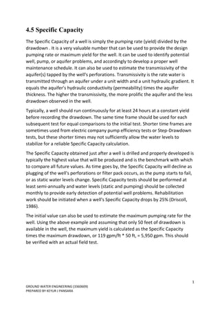
The document discusses specific capacity, which is a measure of well productivity calculated by dividing pumping rate by drawdown. It provides key information about specific capacity, including that it can be used to identify potential well problems, estimate aquifer transmissivity, and determine maximum pumping rates. The document also outlines best practices for specific capacity testing, such as pumping for at least 24 hours and performing semi-annual tests to monitor changes over time. Rehabilitation is recommended when specific capacity drops by 25% from initial values.
![13
GROUND WATER ENGINEERING (3360609)
PREPARED BY KEYUR J PANSARA
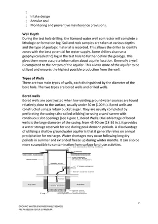
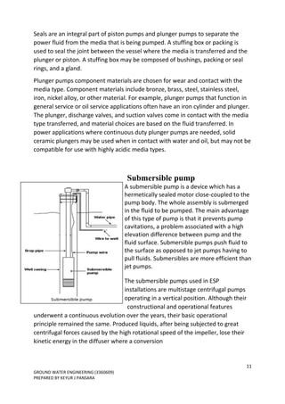
Air lift pump
An airlift pump is a pump that has low
suction and moderate discharge of liquid and
entrained solids. The pump injects
compressed air at the bottom of the
discharge pipe which is immersed in the
liquid. The compressed air mixes with the
liquid causing the air-water mixture to be
less dense than the rest of the liquid around
it and therefore is displaced upwards
through the discharge pipe by the
surrounding liquid of higher density. Solids
may be entrained in the flow and if small enough to fit through the pipe, will be
discharged with the rest of the flow at a shallower depth or above the surface.
Airlift pumps are widely used in aquaculture to pump, circulate and aerate water
in closed, recirculating systems and ponds. Other applications include dredging,
underwater archaeology, salvage operations and collection of scientific
specimens.
The only energy required is provided by compressed air.[citation needed] This air
is usually compressed by a compressor or a blower. The air is injected in the lower
part of a pipe that transports a liquid. By buoyancy the air, which has a lower
density than the liquid, rises quickly. By fluid pressure, the liquid is taken in the
ascendant air flow and moves in the same direction as the air. The calculation of
the volume flow of the liquid is possible thanks to the physics of two-phase flow.
Airlift pumps are often used in deep dirty wells where sand would quickly abrade
mechanical parts. However airlift wells must be much deeper than the water
table to allow for submergence. Air is generally pumped at least as deep under
the water as the water is to be lifted. (If the water table is 50 ft below, the air
should be pumped 100 feet deep).It is also sometimes used in part of the process
on a wastewater treatment plant if a small head is required (typically around 1
foot head).](https://image.slidesharecdn.com/gweengchap4-170320085416/85/Well-Hydraulics-13-320.jpg)