
More Related Content
What's hot
What's hot (20)
Similar to Welding Symbol.ppt
Similar to Welding Symbol.ppt (20)
Recently uploaded
Recently uploaded (20)
Welding Symbol.ppt
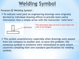
- 1. Purpose Of Welding Symbol : To indicate weld joint on engineering drawings were originally devised by individual drawing offices to provide more useful information than a simple arrow with the instruction ‘weld here’. This symbol unsatisfactory, especially when drawings were passed from one company to another and, to solve this problem, the numerous symbols in existence were rationalized to some extent countries compiling their own standard specifications for welding symbols. Weld Here The information does not tell us much about the wish of the designer
- 2. There are a number of standards throughout the world that relate to weld symbols, but in the United States, AWS A2.4, Standard Symbols for Welding, Brazing, and Non destructive Examination, is the standard. In the global marketplace, the International Organization for Standardization (ISO) has developed ISO 2553:1992, Welded, Brazed, and Soldered Joints Symbolic Representation on Drawings . The weld symbols (ISO 2553 : 1992) in this standard are very similar to AWS A2.4, but there are differences that can cause interpretation difficulties or the incorrect usage of welding symbols for the unacquainted user. In the ISO system, the dashed line can be drawn above or below the solid line but the symbols on the solid line always refer to the arrow side of the joint. It is recommended that the solid line is always drawn above the dashed line as standard practice.
- 5. Welding Symbol BS EN ISO 22553 AWS A2.4 Welding Area Welding Area
- 6. Arrow line Reference lines Arrow side Other side BS EN 22553. Welding Symbols (ISO 2553) Arrow side Other side
- 7. Other side Arrow side Both sides BS EN 22553. Welding Symbols (ISO 2553)
- 8. b a d c BS EN 22553. Welding Symbols (ISO 2553)
- 9. Flat Convex Concave BS EN 22553. Welding Symbols (ISO 2553) Toes shall be blended
- 10. Field weld (site weld) NDT The component requires NDT inspection WPS Additional information, the reference document is included in the box Welding to be carried out all round component (peripheral weld) BS EN 22553. Welding Symbols (ISO 2553)
- 11. s = Deep of penetration a = Design throat thickness z = Leg length a = 0.7 of z a z BS EN 22553. Welding Symbols (ISO 2553) a 4 4mm throat z 6 6mm leg s
- 12. n = number of weld elements l = length of each weld element (e) = distance between each weld element Welds to be staggered Process n x l (e) 2 x 10 (20) 3 x 10 (20) 111 BS EN 22553. Welding Symbols (ISO 2553)
- 14. Single-V Butt flush cap Single-U Butt with sealing run BS EN 22553. Welding Symbols (ISO 2553) Single-V Butt with permanent backing strip M Single-U Butt with removable backing strip M R
- 15. Single-bevel butt Double-bevel butt Single-bevel butt Single-J butt BS EN 22553. Welding Symbols (ISO 2553)
- 16. Partial penetration single-V butt 10 10 BS EN 22553. Welding Symbols (ISO 2553)
- 17. Ans to BS EN 22553 Fillet Welds ex: 1 1. Welded arrow side: A continuous fillet weld with a 6 mm leg length , toes to be blended smoothly. 2. Welded both sides: Three intermittent fillet welds with 6 mm leg lengths, the length of each weld 25 mm and the distance between each weld 40 mm. 3. Welded arrow sides: Three intermittent fillet welds with 10 mm leg lengths, the length of each weld 40 mm, the distance between each weld 30mm. Welded other side: Three intermittent fillet welds 6 mm leg lengths, the length of each weld 50mm and the distance between each weld 25mm, welds to be staggered. 4. Welded arrow side: Three intermittent fillet welds with 8 mm leg lengths, the length of each weld 25 mm and the distance between each weld 50 mm. Welded other side: Two intermittent fillet welds with 10 mm leg lengths, the length of each weld 20 mm and the distance between each weld 40mm, welds to be staggered. 3 x 25 (50) 2 x 20 (40) 10 8 50 50 25 25 40 40 20 20 25 6 40 50 40 50 50 25 25 30 30 40 30 10 6 3 x 40 3 x 50 (25) (30) 3 x 25 (40) 3 x 25 (40) 6 6 25 40 25 40 25 25 25 25 40 40
- 18. Ans to BS EN 22553 Butt Welds ex: 1 1. Welded arrow side: Single ‘V’ butt weld with permanent backing strip, flat weld profile. M 2. Welded other side: Single “U” butt weld, flat weld profile 3. Welded arrow side: Single “V” butt weld depth of preparation 10 mm Welded other side: Backing run. (Plate thickness 15 mm.) 4. Welded arrow side: Single “J” butt weld, depth of preparation 12 mm with a 8 mm fillet weld superimposed. (plate thickness 15 mm. Welded other side: 12 mm leg length fillet weld. 10 12 12 8
- 19. TWIN FRAME TWIN LIFT BOX