SlideShare a Scribd company logo
ISO metric precision hexagon bolts, screws and nuts
are covered by BS 3643 and ISO 272. The standard
includes washer faced hexagon head bolts and full
bearing head bolts. In both cases there is a small radius
under the bolthead which would not normally be shown
on drawings, due to its size, but is included here for
completeness of the text. With an M36 bolt, the radius
is only 1.7 mm. Bolts may be chamfered at 45° at the
end of the shank, or radiused. The rounded end has a
radius of approximately one and one quarter times the
shank diameter and can also be used if required to
draw the rolled thread end. The washer face under the
head is also very thin and for a M36 bolt is only
0.5 mm.
Figure 10.1(a) shows the bolt proportions and Table
10.1 the dimensions for bolts in common use.
Dimensions of suitable nuts are also given and illustrated
in Fig. 10.1(b).
Included in Table 10.1 and shown in Fig. 10.1(c)
are typical washers to suit the above bolts and nuts
and these are covered by BS 4320. Standard washers
are available in two different thicknesses, in steel or
brass, and are normally plain, but may be chamfered.
Table 10.1 gives dimensions of commonly used bolts,
nuts and washers so that these can be used easily on
assembly drawings. For some dimensions maximum
and minimum values appear in the standards and we
have taken an average figure rounded up to the nearest
0.5 mm and this will be found satisfactory for normal
drawing purposes. Reference should be made to the
relevant standards quoted for exact dimensions if
required in design and manufacture.
Drawing nuts and bolts
It is often necessary to draw nuts and bolts and a quick
easy method is required to produce a satisfactory result.
Chapter 10
Nuts, bolts, screws and washers
Table 10.1
D A/C A/F Df H T t
M1.6 0.35 1.1 3.5 3.0 1.0 1.25 1.7 4.0 0.3
M2 0.4 1.4 4.5 4.0 1.5 1.5 2.2 5.0 0.3
M2.5 0.45 1.9 5.5 5.0 1.75 2.0 2.7 6.5 0.5
M3 0.5 2.3 6.0 5.5 5.0 2.0 2.25 3.2 7.0 0.5
M4 0.7 3.0 8.0 7.0 6.5 2.75 3.0 4.3 9.0 0.8
M5 0.8 3.9 9.0 8.0 7.5 3.5 4.0 5.3 10.0 1.0
M6 1.0 4.7 11.5 10.0 9.0 4.0 5.0 6.4 12.5 1.6 0.8
M8 1.25 6.4 15.0 13.0 12.0 5.5 6.5 5.0 8.4 17 1.6 1.0
M10 1.5 8.1 19.5 17.0 16.0 7.0 8.0 6.0 10.5 21 2.0 1.25
M12 1.75 9.7 21.5 19.0 18.0 8.0 10.0 7.0 13.0 24 2.5 1.6
M16 2.0 13.5 27.0 24.0 23.0 10.0 13.0 8.0 17.0 30 3.0 2.0
M20 2.5 16.7 34.0 30.0 29.0 13.0 16.0 9.0 21.0 37 3.0 2.0
M24 3.0 20.0 41.5 36.0 34.5 15.0 19.0 10.0 25.0 44 4.0 2.5
M30 3.5 25.5 52.0 46.0 44.5 19.0 24.0 12.0 31.0 56 4.0 2.5
M36 4.0 31.0 62.5 55.0 53.5 23.0 29.0 14.0 37.0 66 5.0 3.0
Nominal
sizethread
diameter
Thread
pitch
Minor
diameter
ofthread
Width
across
corners
Width
across
flats
Diameter
ofwasher
face
Heightof
bolthead
Thickness
ofnormal
nut
Thickness
ofthinnut
Washer
inside
diameter
Washer
outside
diameter
Washer
thickness
FormA
Washer
thickness
FormB
MCE 310 (Machine Drawing) Lectures by Kilanko O.
77
Nuts and bolts are not normally drawn on detail
drawings unless they are of a special type. They are
shown on assembly drawings and, provided they are
standard stock sizes, are called up in parts lists and
schedules. A description of the head, the thread and
the length being generally sufficient. Templates are
available for drawing nuts and bolts and can be
recommended for their time saving advantages.
It is conventional drawing practice to show, as first
choice, nuts and bolts in the across corners position if
a single view only is illustrated since this is instantly
recognizable.
Approximate construction
for nuts and bolts (Figs
10.2 and 10.3)
Stage 1
1 Draw a circle in the plan position, 2D in diameter,
where D is equal to the thread size. In this example
let us assume that the thread size is M20.
2 Draw a hexagon inside the 40 mm diameter circle
and inside the hexagon draw another circle tangential
to the hexagon on the six sides. This circle is the
projection of the chamfer which can be seen on the
front elevation.
3 the nut thickness is 0.8D. Project the four corners
of the hexagon to the front elevation.
4 Project three corners of the hexagon in the end
elevation and note, that the width of the end elevation
is given by dimension W.
5 Line in the projected diameter of the chamfer circle
and the base in the front elevation.
6 As an approximation, draw a radius to show the
chamfer on the front elevation. The radius should
equal the thread size D.
7 Add the female convention to the plan view.
(b) Precision nuts and thin nuts
A/F
D
A/C
T t
(a) Hexagon head precision bolts
Rolled thread end
Full bearing head (c) Bright washers
d1
d2
Form A Form B
SS
Chamfer
optional
30°
Hexagon head
washer faced
H
Df
Length
D
A/F
A/C
11
4
D
Fig. 10.1 Proportions of bolts, nuts and washers. A/C means across corners. A/F means across flats.
W
0.8D
D
D
W
2D
Fig. 10.2 Stage 1
MCE 310 (Machine Drawing) Lectures by Kilanko O.
78
Stage 2
1 The projection of the curve on the chamfered faces
of the hexagon that lie at an angle would produce
ellipses in the front elevation. In their place we
usually show small circular arcs, their radii can be
found by trial, but are approximately 0.25D.
2 The end elevation of the nut has square corners and
the projection of the corner which coincides with
the centre line terminates at the bottom of the
chamfer curve.
3 Complete the view by drawing circular arcs on the
two chamfered faces. Find by trial, the radius of an
arc which will touch the top of the nut and the
projection lines from the corner in the front elevation.
Reference to Fig. 10.1a and b will show that the
constructions in Fig. 10.2 and Fig. 10.3 can be used
for the bolthead and locknut where proportions for
thickness can be approximated to 0.7D and 0.5D.
For exact dimensions however, please refer to Table
10.1.
Socket head screws manufactured to
BS EN ISO 4762 and BS 3643-2
It is often required to draw these screws and although
the head type and the length are generally quoted in
parts lists it is necessary to know the proportions of
the head. Dimensions follow for each of the most
commonly used screws.
Before specifying screws it is advisable to consult a
manufacturers list for availability. In the interest of
standardization and economy, designers are urged to
use stock lengths wherever possible and standard lengths
of screws include the following; 3, 4, 5, 6, 8, 10, 12,
16, 20, 25, 30, 35, 40, 45, 50, 55, 60, 65, 70, 75, 80,
90, 100, 110, 120, 130, 140, 150, 160, 170, 180, 190,
and 200 mm. If lengths over 200 mm are required,
then increments of 20 mm are the preferred ISO lengths.
It should be understood that not all diameters of screw
are available in the above lengths. For example, the
range of lengths for an M3 screw lies between 5 and
35 mm, for an M10 screw between 12 and 100 mm for
one particular type of head. The same range will also
not cover different types of head, hence the necessity
to check stock lists.
ISO metric socket cap screws
Dimensions in Table 10.2
These screws are distinguished by square knurling on
the heads. Generally, the lengths of standard screws
increase in increments of 5 mm and 10 mm, but the
exact range should be checked from the manufacturers
catalogue.
Fig. 10.3 Stage 2
Table 10.2
Nominal size D M3 M4 M5 M6 M8 M10 M12 M16 M20
Head diameter A 5.5 7 8.5 10 13 16 18 24 30
Head depth H 3 4 5 6 8 10 12 16 20
Key engagement K 1.3 2 2.7 3.3 4.3 5.5 6.6 8.8 10.7
Socket size J 2.5 3 4 5 6 8 10 14 17
Fig. 10.4 ISO metric hexagon socket shoulder screws. Dimensions in
Table 10.3
A
D
K
H Screw length
Thread
length J
ISO metric hexagon socket shoulder
screws
Dimensions in Table 10.3
Table 10.3
Nominal shoulder diameter B 6 8 10 12 16
Head diameter A 10 13 16 18 24
Head height H 4.5 5.5 7 8 10
Socket size J 3 4 5 6 8
Screw thread diameter D M5 M6 M8 M10 M12
Nominal thread length Lt 9.75 11.25 13.25 16.4 18.4
Key engagement K 2.45 3.3 4.15 4.92 6.62
Fig. 10.5 ISO metric hexagon socket button head screws. Dimensions in
Table 10.4
J
Lt
D
B
LH
K
A
MCE 310 (Machine Drawing) Lectures by Kilanko O.
79
ISO metric hexagon socket button head
screws
Dimensions in Table 10.4
and the minimum head angle of 90°. The minimum
head size is controlled by a minimum head diameter,
the maximum head angle of 92° and a flushness
tolerance. The edge of the head may be flat, as shown
in Fig. 10.8, or rounded but not sharp edged (see below).
Table 10.4
Nominal size D M3 M4 M5 M6 M8 M10 M12
Head diameter A 5.5 7.5 9.5 10.5 14 18 21
Head depth H 1.6 2.1 2.7 3.2 4.3 5.3 6.4
Key engagement K 2 2.5 3 4 5 6 8
Socket size J 1.04 1.3 1.56 2.08 2.6 3.12 4.16
Fillet radius
F-minimum 0.1 0.2 0.2 0.25 0.4 0.4 0.6
da-maximum 3.6 4.7 5.7 6.8 9.2 11.2 14.2
S 0.38 0.38 0.5 0.8 0.8 0.8 0.8
Fig. 10.6
LS
D
da
FK
H
A
J
ISO metric socket countersunk
head screws
Dimensions in Table 10.5
The basic requirement for countersunk head screws is
that the head should fit into a countersunk hole with as
great a degree of flushness as possible. Fig. 10.7 and
Table 10.5 give dimensions. To achieve this it is
necessary for both the head of the screw and the
countersunk hole to be controlled within prescribed
limits. The maximum or design size of the head is
controlled by a theoretical diameter to a sharp corner
Table 10.5
Nominal size D M3 M4 M5 M6 M8 M10 M12 M16 M20
Head diameter
A – maximum 6.72 8.96 11.2 13.44 17.92 22.4 26.88 33.6 40.32
B – minimum 5.82 7.78 9.78 11.73 15.73 19.67 23.67 29.67 35.61
Head depth H 1.86 2.48 3.1 3.72 4.96 6.2 7.44 8.8 10.16
Socket size J 2 2.5 3 4 5 6 8 10 12
Key engagement K 1.05 1.49 1.86 2.16 2.85 3.60 4.35 4.89 5.49
Fillet radius
F – minimum 0.1 0.2 0.2 0.25 0.4 0.4 0.6 0.6 0.8
da – maximum 3.4 4.5 5.5 6.6 9 11 14 18 22
Fig. 10.7
90°
B
A
K
H
Lt
F
L
D
da
Sharp corners
removed
Flushness
tolerance
Maximum
profile
Minimum
profile
92°
Min. Head Dia.
Theoretical sharp
90°
Fig. 10.8 ISO metric hexagon socket set screws. Dimensions in
Table 10.6
ISO metric hexagon socket set screws
Dimensions in Table 10.6
These screws are available with a variety of pointed
ends. In all cases the overall length includes the chamfer
at the socket end and the point.
J
D
L
K
MCE 310 (Machine Drawing) Lectures by Kilanko O.
80
‘screws’ applies to products which are threaded up to
the head or having an unthreaded portion of the shank.
The length of the thread is defined as the distance
from the end of the screw, and this includes any chamfer,
radius or cone point, to the leading face of the nut
which has been screwed as far as possible onto the
screw by hand. Note on the illustrations which follow
that in the case of the countersunk head types of screw,
the length of the screw includes the countersunk part
of the head. For pan and cheese head screws, the screw
length does not include the head.
The Standard should be consulted for manufacturing
dimensional tolerances, also concentricity tolerances
for the heads of the screws.
The illustrations which follow show each of the
screws and tables are also given showing the dimensions
of regularly used sizes.
The sizes quoted in the tables are for screws
manufactured in steel. Standard screws are also available
in brass but generally the range is not quite so extensive.
For all of the machine screws illustrated here, the
countersunk head types have an included angle of 90°.
‘Posidriv’ machine screws, countersunk
and raised countersunk head
Dimensions in Table 10.7
Table 10.6
Nominal size D M3 M4 M5 M6 M8 M10 M12 M16 M20
Socket size J 1.5 2 2.5 3 4 5 6 8 10
Key engagement K 1.2 1.6 2 2.4 3.2 4 4.8 6.4 8
Dog point diameter P 2 2.5 3.5 4.5 6 7 9 12 15
Dog point length Q 0.88 1.12 1.38 1.62 2.12 2.62 3.12 4.15 5.15
Cup point and ‘W’
point diameter C 1.4 2 2.5 3 5 6 8 10 14
Note: The cone point angle shown as Y° is generally 118° for short screws and 90° for longer lengths.
Y°
P
Q
(b)(a)
90°
C
90° 118°
C
(d)(c)
Fig. 10.9 (a) Cone point (b) Dog point (c) W point (d) Cup point
Fig. 10.10 Typical GKN socket screws and wrench
d
L
H
D
Fig. 10.11 Countersunk head
d
D
H
L
Machine screws
Head shapes for machine screws have been rationalized
in BS EN ISO 1580 and BS EN ISO 7045. For the
purpose of this British Standard, the generic term Fig. 10.12 Raised countersunk head
MCE 310 (Machine Drawing) Lectures by Kilanko O.
81
‘Posidriv’ machine screws, pan head
Dimensions in Table 10.8
Table 10.7
Diameter Dia of head Depth of head Driver Length
d D H no. L
M2 4.40 1.20 1 4 5 6 8 10 12
M2.5 5.50 1.50 1 5 6 8 10 12 16 20 25
M3 6.30 1.65 1 5 6 8 10 12 16 20 25
M3.5 7.35 1.93 2 6 8 10 12 16 20 25 30
M4 8.40 2.20 2 6 8 10 12 16 20 25 30
M5 10.00 2.50 2 6 8 10 12 16 20 25 30 35 40 45 50
M6 12.00 3.00 3 10 12 16 20 25 30 35 40 45 50 55 60
M8 16.00 4.00 4 12 16 20 25 30 40 50 60
M10 20.00 5.00 4 16 20 25 30 40 50 60
Slotted machine screws, countersunk
and raised countersunk head
Dimensions in Table 10.9
Table 10.8
Diameter Dia of head Depth of head Driver Length
d D H no. L
M2 4.00 1.60 1 4 5 6 8 10 12
M2.5 5.00 1.75 1 5 6 8 10 12 16 20 25
M3 6.00 2.10 1 5 6 8 10 12 16 20 25
M3.5 7.00 2.45 2 6 8 10 12 16 20 25 30
M4 8.00 2.80 2 5 6 8 10 12 16 20 25 30
M5 10.00 3.50 2 6 8 10 12 16 20 25 30 35 40 45 50
M6 12.00 4.20 3 10 12 16 20 25 30 35 40 45 50 55 60
M8 16.00 5.60 4 16 20 25 30 40 50
M10 20.00 7.00 4 20 25 30 40
H L
D
d
Fig. 10.13
L
H
D
d
D
d
H
L
Fig. 10.14 Countersunk head Fig. 10.15 Raised countersunk head
MCE 310 (Machine Drawing) Lectures by Kilanko O.
82
Slotted machine screws, cheese head
Dimensions in Table 10.11
Table 10.9
Diameter Dia of head Depth of head Length
d D H L
M2 4.40 1.20 5 6 8 10 12
M2.5 5.50 1.50 5 6 8 10 12 16 20 25
M3 6.30 1.65 5 6 8 10 12 16 20 25 30 35 40 45 50
M3.5 7.35 1.93 5 6 8 10 12 16 20 25 30 35 40 45 50 60
M4 8.40 2.20 5 6 8 10 12 16 20 25 30 35 40 45 50 60 70
M5 10.00 2.50 6 8 10 12 16 20 25 30 35 40 45 50 60 70 80
M6 12.00 3.00 8 10 12 16 20 25 30 35 40 45 50 60 70 80 90
M8 16.00 4.00 10 12 16 20 25 30 35 40 45 50 60 70 80 90
M10 20.00 5.00 16 20 25 30 35 40 45 50 55 60 70 80 90
Slotted machine screws, pan head
Dimensions in Table 10.10
Fig. 10.16
D
d
LH
Table 10.10
Diameter Dia of head Depth of Length
d D head H L
M2 4.00 1.20 4 5 6 8 10 12
M2.5 5.00 1.50 5 6 8 10 12 16 20 25
M3 6.00 1.80 5 6 8 10 12 16 20 25 30 35 40 45 50
M3.5 7.00 2.10 6 8 10 12 16 20 25 30 35 40 45 50
M4 8.00 2.40 5 6 8 10 12 16 20 25 30 35 40 45 50
M5 10.00 3.00 6 8 10 12 16 20 25 30 35 40 45 50 55 60 70 80
M6 12.00 3.60 8 10 12 16 20 25 30 35 40 45 50 55 60 70 80
M8 16.00 4.80 10 12 16 20 25 30 40 50 60 70 80 90
M10 20.00 6.00 16 20 25 30 40 50 60 70
Fig. 10.17
LH
d
D
MCE 310 (Machine Drawing) Lectures by Kilanko O.
83
Machine screw nuts
A range of machine screw nuts is covered by BS EN
ISO 1580 and BS EN ISO 7045 and these nuts are
manufactured in two different patterns, square and
hexagon. The table shows typical nuts for use with the
screws previously described.
Table 10.11
Diameter Dia of head Depth of Length
d D head H L
M2 3.80 1.30 3 4 5 6 8 10 12 16 20 25
M2.5 4.50 1.60 5 6 8 10 12 16 20 25 30
M3 5.50 2.00 4 5 6 8 10 12 16 20 25 30 35 40 45 50
M3.5 6.00 2.40 5 6 8 10 12 16 20 25 30 35 40 45 50 60 70
M4 7.00 2.60 5 6 8 10 12 16 20 25 30 35 40 45 50 60 70
M5 8.50 3.30 6 8 10 12 16 20 25 30 35 40 45 50 60 70 80 90
M6 10.00 3.90 8 10 12 16 20 25 30 35 40 45 50 60 70 80 90
M8 13.00 5.00 10 12 16 20 25 30 35 40 45 50 60 70 80 90
M10 16.00 6.00 16 20 25 30 35 40 45 50 60 70 80 90
Table 10.12 Machine screw nuts, pressed type, square and hexagonal
Nominal size Width across Width across corners e Thickness
of nut d flats s
Square Hexagon
m
M2 4.0 5.7 4.6 1.2
M2.5 5.0 7.1 5.8 1.6
M3 5.5 7.8 6.4 1.6
M3.5 6.0 8.5 6.9 2.0
M4 7.0 9.9 8.1 2.0
M5 8.0 11.3 9.2 2.5
M6 10.0 14.1 11.5 3.0
M8 13.0 18.4 15.0 4.0
M10 17.0 24.0 19.6 5.0
Fig. 10.18 Square nut
m
d
s
e
Wing nuts
Figure 10.20 shows the dimensions of preferred sizes
of wing nuts manufactured in brass or malleable iron
by a hot stamping or casting process.
m
s
e
d
Fig. 10.19 Hexagon nut
Fig. 10.20 (Sizes are in Table 16.13)
E
G
D
F
Thread
size
Alternative
wing shape A
H
J
B
C
Small rad
in corner
Table 10.13
Thread size A B C D E F G H J
M3 9 6.5 7 13.5 22 19 3.5 2.5 1.5
M4 and M5 10 8 9 15 25.5 19 4 2.5 1.5
M6 13 9.5 11 18 30 19 5 2.5 1.5
M8 16 12 13 23 38 19 6.5 3 2.5
M10 17.5 14 14 25.5 44.5 19 7 5 3
M12 19 16 15 28.5 51 25.5 8 5 3
M16 25.5 20.5 19 36.5 63.5 32 10 6.5 5
An alternative wing nut is available in brass or
malleable iron and manufactured by cold forging.
MCE 310 (Machine Drawing) Lectures by Kilanko O.
84

More Related Content

What's hot

Engineering Drawing: Chapter 11 thread fastener
Engineering Drawing: Chapter 11 thread fastenerEngineering Drawing: Chapter 11 thread fastener
Engineering Drawing: Chapter 11 thread fastenermokhtar
 
Engineering Drawing: Chapter 10 convention in section
Engineering Drawing: Chapter 10 convention in sectionEngineering Drawing: Chapter 10 convention in section
Engineering Drawing: Chapter 10 convention in sectionmokhtar
 
Lathe Machine
Lathe MachineLathe Machine
Lathe Machine
RANJIT TAWARE
 
Machine drawing notes 15 me34d
Machine drawing notes 15 me34dMachine drawing notes 15 me34d
Machine drawing notes 15 me34d
THANMAY JS
 
#Machine Drawing Complete lecture notes
#Machine Drawing Complete lecture notes#Machine Drawing Complete lecture notes
#Machine Drawing Complete lecture notes
MOKSHIT TECH
 
Engineering Drawing: Chapter 12 working drawing
Engineering Drawing: Chapter 12 working drawingEngineering Drawing: Chapter 12 working drawing
Engineering Drawing: Chapter 12 working drawingmokhtar
 
Design of Welded Joints
Design of Welded JointsDesign of Welded Joints
Design of Welded Joints
MechBalu1
 
Engineering drawing unit 1-snist
Engineering drawing unit 1-snistEngineering drawing unit 1-snist
Engineering drawing unit 1-snist
Kunduru Srinivasulu Reddy
 
sectional views
sectional viewssectional views
sectional views
vikash singh
 
Sheet metal operations part 1
Sheet metal operations part 1Sheet metal operations part 1
Sheet metal operations part 1
Dr. L K Bhagi
 
Welding symbol
Welding symbolWelding symbol
Welding symbol
Tori Tom
 
Riveted joints
Riveted jointsRiveted joints
Riveted joints
MANOHAR BABU
 
Riveted joints 200708
Riveted joints 200708Riveted joints 200708
Riveted joints 200708
Shehbaz Ali
 
Assembly and Details
Assembly and Details  Assembly and Details
Assembly and Details
umesh chikhale
 
Machining technology lab manual mechanical.manufacturing technology 2 lab manual
Machining technology lab manual mechanical.manufacturing technology 2 lab manualMachining technology lab manual mechanical.manufacturing technology 2 lab manual
Machining technology lab manual mechanical.manufacturing technology 2 lab manual
ali raza
 
Types of dies
Types of diesTypes of dies
limits,fits and tolerances
limits,fits and toleranceslimits,fits and tolerances
limits,fits and tolerances
JOSE BABU
 
Basics of Sheetmetal operations
Basics of Sheetmetal operationsBasics of Sheetmetal operations
Basics of Sheetmetal operations
Raghavendra Byluri
 

What's hot (20)

Engineering Drawing: Chapter 11 thread fastener
Engineering Drawing: Chapter 11 thread fastenerEngineering Drawing: Chapter 11 thread fastener
Engineering Drawing: Chapter 11 thread fastener
 
Engineering Drawing: Chapter 10 convention in section
Engineering Drawing: Chapter 10 convention in sectionEngineering Drawing: Chapter 10 convention in section
Engineering Drawing: Chapter 10 convention in section
 
Lathe Machine
Lathe MachineLathe Machine
Lathe Machine
 
Machine drawing notes 15 me34d
Machine drawing notes 15 me34dMachine drawing notes 15 me34d
Machine drawing notes 15 me34d
 
Chapter 09 section
Chapter 09 sectionChapter 09 section
Chapter 09 section
 
#Machine Drawing Complete lecture notes
#Machine Drawing Complete lecture notes#Machine Drawing Complete lecture notes
#Machine Drawing Complete lecture notes
 
Engineering Drawing: Chapter 12 working drawing
Engineering Drawing: Chapter 12 working drawingEngineering Drawing: Chapter 12 working drawing
Engineering Drawing: Chapter 12 working drawing
 
Design of Welded Joints
Design of Welded JointsDesign of Welded Joints
Design of Welded Joints
 
Engineering drawing unit 1-snist
Engineering drawing unit 1-snistEngineering drawing unit 1-snist
Engineering drawing unit 1-snist
 
sectional views
sectional viewssectional views
sectional views
 
Sheet metal operations part 1
Sheet metal operations part 1Sheet metal operations part 1
Sheet metal operations part 1
 
Welding symbol
Welding symbolWelding symbol
Welding symbol
 
Riveted joints
Riveted jointsRiveted joints
Riveted joints
 
Riveted joints 200708
Riveted joints 200708Riveted joints 200708
Riveted joints 200708
 
Assembly and Details
Assembly and Details  Assembly and Details
Assembly and Details
 
Machining technology lab manual mechanical.manufacturing technology 2 lab manual
Machining technology lab manual mechanical.manufacturing technology 2 lab manualMachining technology lab manual mechanical.manufacturing technology 2 lab manual
Machining technology lab manual mechanical.manufacturing technology 2 lab manual
 
Types of dies
Types of diesTypes of dies
Types of dies
 
Sheet metal operations1class
Sheet metal operations1class Sheet metal operations1class
Sheet metal operations1class
 
limits,fits and tolerances
limits,fits and toleranceslimits,fits and tolerances
limits,fits and tolerances
 
Basics of Sheetmetal operations
Basics of Sheetmetal operationsBasics of Sheetmetal operations
Basics of Sheetmetal operations
 

Viewers also liked

Bolts includes docs_pdf_87
Bolts includes docs_pdf_87Bolts includes docs_pdf_87
Bolts includes docs_pdf_87Pinak Nandasana
 
Technical metric fasteners
Technical metric fastenersTechnical metric fasteners
Technical metric fastenersPinak Nandasana
 
Weight chart for_hexagon_bolts_&_nuts
Weight chart for_hexagon_bolts_&_nutsWeight chart for_hexagon_bolts_&_nuts
Weight chart for_hexagon_bolts_&_nuts
Manish Thakur
 
Introduction to Engineering Graphics
Introduction to Engineering Graphics Introduction to Engineering Graphics
Introduction to Engineering Graphics
Nitin Shekapure
 
Final engineering graphics_xii_pdf_for_web
Final engineering graphics_xii_pdf_for_webFinal engineering graphics_xii_pdf_for_web
Final engineering graphics_xii_pdf_for_webCarl Witmore
 
Projections of solids
Projections of solidsProjections of solids
Projections of solids
Kunduru Srinivasulu Reddy
 
Marvellous 'Baha'i Temple' or ' Lotus Temple'
Marvellous 'Baha'i Temple' or ' Lotus Temple'Marvellous 'Baha'i Temple' or ' Lotus Temple'
Marvellous 'Baha'i Temple' or ' Lotus Temple'
Chandra Sekhar P
 

Viewers also liked (7)

Bolts includes docs_pdf_87
Bolts includes docs_pdf_87Bolts includes docs_pdf_87
Bolts includes docs_pdf_87
 
Technical metric fasteners
Technical metric fastenersTechnical metric fasteners
Technical metric fasteners
 
Weight chart for_hexagon_bolts_&_nuts
Weight chart for_hexagon_bolts_&_nutsWeight chart for_hexagon_bolts_&_nuts
Weight chart for_hexagon_bolts_&_nuts
 
Introduction to Engineering Graphics
Introduction to Engineering Graphics Introduction to Engineering Graphics
Introduction to Engineering Graphics
 
Final engineering graphics_xii_pdf_for_web
Final engineering graphics_xii_pdf_for_webFinal engineering graphics_xii_pdf_for_web
Final engineering graphics_xii_pdf_for_web
 
Projections of solids
Projections of solidsProjections of solids
Projections of solids
 
Marvellous 'Baha'i Temple' or ' Lotus Temple'
Marvellous 'Baha'i Temple' or ' Lotus Temple'Marvellous 'Baha'i Temple' or ' Lotus Temple'
Marvellous 'Baha'i Temple' or ' Lotus Temple'
 

Similar to Nuts bolts-screws-washers

Chapter 11 Thread Fastener.ppt
Chapter 11 Thread Fastener.pptChapter 11 Thread Fastener.ppt
Chapter 11 Thread Fastener.ppt
Dr. Imran Nazir Unar
 
Screw Thread Terms for beginners in engineering- Gdlc(1).pdf
Screw Thread Terms  for beginners in engineering- Gdlc(1).pdfScrew Thread Terms  for beginners in engineering- Gdlc(1).pdf
Screw Thread Terms for beginners in engineering- Gdlc(1).pdf
OKIDIThomasBecket
 
DC MACHINE
DC MACHINEDC MACHINE
DC MACHINE
Mahesh Obannavar
 
4.main content final copy edited (2)
4.main content final copy edited (2)4.main content final copy edited (2)
4.main content final copy edited (2)
MothilalThulasiraman
 
Theory for Welded connection.pdf
Theory for Welded connection.pdfTheory for Welded connection.pdf
Theory for Welded connection.pdf
YatiTank
 
Screw and Barrel Inspection
Screw and Barrel InspectionScrew and Barrel Inspection
Screw and Barrel Inspection
R&B Plastics Machinery
 
Chapter 08
Chapter 08Chapter 08
Chapter 08mcfalltj
 
153-cable glands
153-cable glands153-cable glands
153-cable glands
Ex-Sabagostar
 
Design of a Gear Reducer for a Tractor
Design of a Gear Reducer for a TractorDesign of a Gear Reducer for a Tractor
Design of a Gear Reducer for a Tractorfodork6
 
TECHNICAL DRAWING CONVENTIONS LISTSS.pdf
TECHNICAL DRAWING CONVENTIONS LISTSS.pdfTECHNICAL DRAWING CONVENTIONS LISTSS.pdf
TECHNICAL DRAWING CONVENTIONS LISTSS.pdf
YadevJaggernauth
 
3 weld symbols
3 weld symbols3 weld symbols
3 weld symbols
depedavr44
 
3_weld_symbols.ppt
3_weld_symbols.ppt3_weld_symbols.ppt
3_weld_symbols.ppt
SrinivasanMuthuvel
 
5.1 Screwed Fasteners.pptx
5.1 Screwed Fasteners.pptx5.1 Screwed Fasteners.pptx
5.1 Screwed Fasteners.pptx
tilahunyeshiye
 
3341906 pms lab_manual_prepared by vipul hingu
3341906 pms lab_manual_prepared by vipul hingu3341906 pms lab_manual_prepared by vipul hingu
3341906 pms lab_manual_prepared by vipul hingu
Vipul Hingu
 
Agriculture CAD lab manual
Agriculture CAD lab manualAgriculture CAD lab manual
Agriculture CAD lab manual
VinothRengaraj2
 
Thread ans weld joints
Thread ans weld jointsThread ans weld joints
Thread ans weld joints
Ajit C
 
Mrr77 07
Mrr77 07Mrr77 07
Mrr77 07
Dave Davidson
 
Pulley catalog-11-05-low
Pulley catalog-11-05-lowPulley catalog-11-05-low
Pulley catalog-11-05-low
mkpq pasha
 
Tabela diametro furo_para_fazer_rosca
Tabela diametro furo_para_fazer_roscaTabela diametro furo_para_fazer_rosca
Tabela diametro furo_para_fazer_rosca
KLELTON BENETÃO
 
Flange Size.docx
Flange Size.docxFlange Size.docx
Flange Size.docx
lyonel2
 

Similar to Nuts bolts-screws-washers (20)

Chapter 11 Thread Fastener.ppt
Chapter 11 Thread Fastener.pptChapter 11 Thread Fastener.ppt
Chapter 11 Thread Fastener.ppt
 
Screw Thread Terms for beginners in engineering- Gdlc(1).pdf
Screw Thread Terms  for beginners in engineering- Gdlc(1).pdfScrew Thread Terms  for beginners in engineering- Gdlc(1).pdf
Screw Thread Terms for beginners in engineering- Gdlc(1).pdf
 
DC MACHINE
DC MACHINEDC MACHINE
DC MACHINE
 
4.main content final copy edited (2)
4.main content final copy edited (2)4.main content final copy edited (2)
4.main content final copy edited (2)
 
Theory for Welded connection.pdf
Theory for Welded connection.pdfTheory for Welded connection.pdf
Theory for Welded connection.pdf
 
Screw and Barrel Inspection
Screw and Barrel InspectionScrew and Barrel Inspection
Screw and Barrel Inspection
 
Chapter 08
Chapter 08Chapter 08
Chapter 08
 
153-cable glands
153-cable glands153-cable glands
153-cable glands
 
Design of a Gear Reducer for a Tractor
Design of a Gear Reducer for a TractorDesign of a Gear Reducer for a Tractor
Design of a Gear Reducer for a Tractor
 
TECHNICAL DRAWING CONVENTIONS LISTSS.pdf
TECHNICAL DRAWING CONVENTIONS LISTSS.pdfTECHNICAL DRAWING CONVENTIONS LISTSS.pdf
TECHNICAL DRAWING CONVENTIONS LISTSS.pdf
 
3 weld symbols
3 weld symbols3 weld symbols
3 weld symbols
 
3_weld_symbols.ppt
3_weld_symbols.ppt3_weld_symbols.ppt
3_weld_symbols.ppt
 
5.1 Screwed Fasteners.pptx
5.1 Screwed Fasteners.pptx5.1 Screwed Fasteners.pptx
5.1 Screwed Fasteners.pptx
 
3341906 pms lab_manual_prepared by vipul hingu
3341906 pms lab_manual_prepared by vipul hingu3341906 pms lab_manual_prepared by vipul hingu
3341906 pms lab_manual_prepared by vipul hingu
 
Agriculture CAD lab manual
Agriculture CAD lab manualAgriculture CAD lab manual
Agriculture CAD lab manual
 
Thread ans weld joints
Thread ans weld jointsThread ans weld joints
Thread ans weld joints
 
Mrr77 07
Mrr77 07Mrr77 07
Mrr77 07
 
Pulley catalog-11-05-low
Pulley catalog-11-05-lowPulley catalog-11-05-low
Pulley catalog-11-05-low
 
Tabela diametro furo_para_fazer_rosca
Tabela diametro furo_para_fazer_roscaTabela diametro furo_para_fazer_rosca
Tabela diametro furo_para_fazer_rosca
 
Flange Size.docx
Flange Size.docxFlange Size.docx
Flange Size.docx
 

More from Obuekwec

Chapter 02 thread fastener
Chapter 02 thread fastenerChapter 02 thread fastener
Chapter 02 thread fastener
Obuekwec
 
Chapter 01 working drawing
Chapter 01 working drawingChapter 01 working drawing
Chapter 01 working drawing
Obuekwec
 
7...files miscellaneous fits___tolerances
7...files miscellaneous fits___tolerances7...files miscellaneous fits___tolerances
7...files miscellaneous fits___tolerances
Obuekwec
 
Chapter 05 convention in section
Chapter 05 convention in sectionChapter 05 convention in section
Chapter 05 convention in section
Obuekwec
 
Chapter 04 section
Chapter 04 sectionChapter 04 section
Chapter 04 section
Obuekwec
 
Chapter 03 orthographic convention
Chapter 03 orthographic conventionChapter 03 orthographic convention
Chapter 03 orthographic convention
Obuekwec
 

More from Obuekwec (6)

Chapter 02 thread fastener
Chapter 02 thread fastenerChapter 02 thread fastener
Chapter 02 thread fastener
 
Chapter 01 working drawing
Chapter 01 working drawingChapter 01 working drawing
Chapter 01 working drawing
 
7...files miscellaneous fits___tolerances
7...files miscellaneous fits___tolerances7...files miscellaneous fits___tolerances
7...files miscellaneous fits___tolerances
 
Chapter 05 convention in section
Chapter 05 convention in sectionChapter 05 convention in section
Chapter 05 convention in section
 
Chapter 04 section
Chapter 04 sectionChapter 04 section
Chapter 04 section
 
Chapter 03 orthographic convention
Chapter 03 orthographic conventionChapter 03 orthographic convention
Chapter 03 orthographic convention
 

Recently uploaded

在线办理(ANU毕业证书)澳洲国立大学毕业证录取通知书一模一样
在线办理(ANU毕业证书)澳洲国立大学毕业证录取通知书一模一样在线办理(ANU毕业证书)澳洲国立大学毕业证录取通知书一模一样
在线办理(ANU毕业证书)澳洲国立大学毕业证录取通知书一模一样
obonagu
 
ASME IX(9) 2007 Full Version .pdf
ASME IX(9)  2007 Full Version       .pdfASME IX(9)  2007 Full Version       .pdf
ASME IX(9) 2007 Full Version .pdf
AhmedHussein950959
 
Hierarchical Digital Twin of a Naval Power System
Hierarchical Digital Twin of a Naval Power SystemHierarchical Digital Twin of a Naval Power System
Hierarchical Digital Twin of a Naval Power System
Kerry Sado
 
Investor-Presentation-Q1FY2024 investor presentation document.pptx
Investor-Presentation-Q1FY2024 investor presentation document.pptxInvestor-Presentation-Q1FY2024 investor presentation document.pptx
Investor-Presentation-Q1FY2024 investor presentation document.pptx
AmarGB2
 
一比一原版(IIT毕业证)伊利诺伊理工大学毕业证成绩单专业办理
一比一原版(IIT毕业证)伊利诺伊理工大学毕业证成绩单专业办理一比一原版(IIT毕业证)伊利诺伊理工大学毕业证成绩单专业办理
一比一原版(IIT毕业证)伊利诺伊理工大学毕业证成绩单专业办理
zwunae
 
Runway Orientation Based on the Wind Rose Diagram.pptx
Runway Orientation Based on the Wind Rose Diagram.pptxRunway Orientation Based on the Wind Rose Diagram.pptx
Runway Orientation Based on the Wind Rose Diagram.pptx
SupreethSP4
 
road safety engineering r s e unit 3.pdf
road safety engineering  r s e unit 3.pdfroad safety engineering  r s e unit 3.pdf
road safety engineering r s e unit 3.pdf
VENKATESHvenky89705
 
Railway Signalling Principles Edition 3.pdf
Railway Signalling Principles Edition 3.pdfRailway Signalling Principles Edition 3.pdf
Railway Signalling Principles Edition 3.pdf
TeeVichai
 
Sachpazis:Terzaghi Bearing Capacity Estimation in simple terms with Calculati...
Sachpazis:Terzaghi Bearing Capacity Estimation in simple terms with Calculati...Sachpazis:Terzaghi Bearing Capacity Estimation in simple terms with Calculati...
Sachpazis:Terzaghi Bearing Capacity Estimation in simple terms with Calculati...
Dr.Costas Sachpazis
 
Pile Foundation by Venkatesh Taduvai (Sub Geotechnical Engineering II)-conver...
Pile Foundation by Venkatesh Taduvai (Sub Geotechnical Engineering II)-conver...Pile Foundation by Venkatesh Taduvai (Sub Geotechnical Engineering II)-conver...
Pile Foundation by Venkatesh Taduvai (Sub Geotechnical Engineering II)-conver...
AJAYKUMARPUND1
 
AP LAB PPT.pdf ap lab ppt no title specific
AP LAB PPT.pdf ap lab ppt no title specificAP LAB PPT.pdf ap lab ppt no title specific
AP LAB PPT.pdf ap lab ppt no title specific
BrazilAccount1
 
NO1 Uk best vashikaran specialist in delhi vashikaran baba near me online vas...
NO1 Uk best vashikaran specialist in delhi vashikaran baba near me online vas...NO1 Uk best vashikaran specialist in delhi vashikaran baba near me online vas...
NO1 Uk best vashikaran specialist in delhi vashikaran baba near me online vas...
Amil Baba Dawood bangali
 
一比一原版(UofT毕业证)多伦多大学毕业证成绩单如何办理
一比一原版(UofT毕业证)多伦多大学毕业证成绩单如何办理一比一原版(UofT毕业证)多伦多大学毕业证成绩单如何办理
一比一原版(UofT毕业证)多伦多大学毕业证成绩单如何办理
ydteq
 
block diagram and signal flow graph representation
block diagram and signal flow graph representationblock diagram and signal flow graph representation
block diagram and signal flow graph representation
Divya Somashekar
 
Gen AI Study Jams _ For the GDSC Leads in India.pdf
Gen AI Study Jams _ For the GDSC Leads in India.pdfGen AI Study Jams _ For the GDSC Leads in India.pdf
Gen AI Study Jams _ For the GDSC Leads in India.pdf
gdsczhcet
 
一比一原版(SFU毕业证)西蒙菲莎大学毕业证成绩单如何办理
一比一原版(SFU毕业证)西蒙菲莎大学毕业证成绩单如何办理一比一原版(SFU毕业证)西蒙菲莎大学毕业证成绩单如何办理
一比一原版(SFU毕业证)西蒙菲莎大学毕业证成绩单如何办理
bakpo1
 
WATER CRISIS and its solutions-pptx 1234
WATER CRISIS and its solutions-pptx 1234WATER CRISIS and its solutions-pptx 1234
WATER CRISIS and its solutions-pptx 1234
AafreenAbuthahir2
 
RAT: Retrieval Augmented Thoughts Elicit Context-Aware Reasoning in Long-Hori...
RAT: Retrieval Augmented Thoughts Elicit Context-Aware Reasoning in Long-Hori...RAT: Retrieval Augmented Thoughts Elicit Context-Aware Reasoning in Long-Hori...
RAT: Retrieval Augmented Thoughts Elicit Context-Aware Reasoning in Long-Hori...
thanhdowork
 
Hybrid optimization of pumped hydro system and solar- Engr. Abdul-Azeez.pdf
Hybrid optimization of pumped hydro system and solar- Engr. Abdul-Azeez.pdfHybrid optimization of pumped hydro system and solar- Engr. Abdul-Azeez.pdf
Hybrid optimization of pumped hydro system and solar- Engr. Abdul-Azeez.pdf
fxintegritypublishin
 
H.Seo, ICLR 2024, MLILAB, KAIST AI.pdf
H.Seo,  ICLR 2024, MLILAB,  KAIST AI.pdfH.Seo,  ICLR 2024, MLILAB,  KAIST AI.pdf
H.Seo, ICLR 2024, MLILAB, KAIST AI.pdf
MLILAB
 

Recently uploaded (20)

在线办理(ANU毕业证书)澳洲国立大学毕业证录取通知书一模一样
在线办理(ANU毕业证书)澳洲国立大学毕业证录取通知书一模一样在线办理(ANU毕业证书)澳洲国立大学毕业证录取通知书一模一样
在线办理(ANU毕业证书)澳洲国立大学毕业证录取通知书一模一样
 
ASME IX(9) 2007 Full Version .pdf
ASME IX(9)  2007 Full Version       .pdfASME IX(9)  2007 Full Version       .pdf
ASME IX(9) 2007 Full Version .pdf
 
Hierarchical Digital Twin of a Naval Power System
Hierarchical Digital Twin of a Naval Power SystemHierarchical Digital Twin of a Naval Power System
Hierarchical Digital Twin of a Naval Power System
 
Investor-Presentation-Q1FY2024 investor presentation document.pptx
Investor-Presentation-Q1FY2024 investor presentation document.pptxInvestor-Presentation-Q1FY2024 investor presentation document.pptx
Investor-Presentation-Q1FY2024 investor presentation document.pptx
 
一比一原版(IIT毕业证)伊利诺伊理工大学毕业证成绩单专业办理
一比一原版(IIT毕业证)伊利诺伊理工大学毕业证成绩单专业办理一比一原版(IIT毕业证)伊利诺伊理工大学毕业证成绩单专业办理
一比一原版(IIT毕业证)伊利诺伊理工大学毕业证成绩单专业办理
 
Runway Orientation Based on the Wind Rose Diagram.pptx
Runway Orientation Based on the Wind Rose Diagram.pptxRunway Orientation Based on the Wind Rose Diagram.pptx
Runway Orientation Based on the Wind Rose Diagram.pptx
 
road safety engineering r s e unit 3.pdf
road safety engineering  r s e unit 3.pdfroad safety engineering  r s e unit 3.pdf
road safety engineering r s e unit 3.pdf
 
Railway Signalling Principles Edition 3.pdf
Railway Signalling Principles Edition 3.pdfRailway Signalling Principles Edition 3.pdf
Railway Signalling Principles Edition 3.pdf
 
Sachpazis:Terzaghi Bearing Capacity Estimation in simple terms with Calculati...
Sachpazis:Terzaghi Bearing Capacity Estimation in simple terms with Calculati...Sachpazis:Terzaghi Bearing Capacity Estimation in simple terms with Calculati...
Sachpazis:Terzaghi Bearing Capacity Estimation in simple terms with Calculati...
 
Pile Foundation by Venkatesh Taduvai (Sub Geotechnical Engineering II)-conver...
Pile Foundation by Venkatesh Taduvai (Sub Geotechnical Engineering II)-conver...Pile Foundation by Venkatesh Taduvai (Sub Geotechnical Engineering II)-conver...
Pile Foundation by Venkatesh Taduvai (Sub Geotechnical Engineering II)-conver...
 
AP LAB PPT.pdf ap lab ppt no title specific
AP LAB PPT.pdf ap lab ppt no title specificAP LAB PPT.pdf ap lab ppt no title specific
AP LAB PPT.pdf ap lab ppt no title specific
 
NO1 Uk best vashikaran specialist in delhi vashikaran baba near me online vas...
NO1 Uk best vashikaran specialist in delhi vashikaran baba near me online vas...NO1 Uk best vashikaran specialist in delhi vashikaran baba near me online vas...
NO1 Uk best vashikaran specialist in delhi vashikaran baba near me online vas...
 
一比一原版(UofT毕业证)多伦多大学毕业证成绩单如何办理
一比一原版(UofT毕业证)多伦多大学毕业证成绩单如何办理一比一原版(UofT毕业证)多伦多大学毕业证成绩单如何办理
一比一原版(UofT毕业证)多伦多大学毕业证成绩单如何办理
 
block diagram and signal flow graph representation
block diagram and signal flow graph representationblock diagram and signal flow graph representation
block diagram and signal flow graph representation
 
Gen AI Study Jams _ For the GDSC Leads in India.pdf
Gen AI Study Jams _ For the GDSC Leads in India.pdfGen AI Study Jams _ For the GDSC Leads in India.pdf
Gen AI Study Jams _ For the GDSC Leads in India.pdf
 
一比一原版(SFU毕业证)西蒙菲莎大学毕业证成绩单如何办理
一比一原版(SFU毕业证)西蒙菲莎大学毕业证成绩单如何办理一比一原版(SFU毕业证)西蒙菲莎大学毕业证成绩单如何办理
一比一原版(SFU毕业证)西蒙菲莎大学毕业证成绩单如何办理
 
WATER CRISIS and its solutions-pptx 1234
WATER CRISIS and its solutions-pptx 1234WATER CRISIS and its solutions-pptx 1234
WATER CRISIS and its solutions-pptx 1234
 
RAT: Retrieval Augmented Thoughts Elicit Context-Aware Reasoning in Long-Hori...
RAT: Retrieval Augmented Thoughts Elicit Context-Aware Reasoning in Long-Hori...RAT: Retrieval Augmented Thoughts Elicit Context-Aware Reasoning in Long-Hori...
RAT: Retrieval Augmented Thoughts Elicit Context-Aware Reasoning in Long-Hori...
 
Hybrid optimization of pumped hydro system and solar- Engr. Abdul-Azeez.pdf
Hybrid optimization of pumped hydro system and solar- Engr. Abdul-Azeez.pdfHybrid optimization of pumped hydro system and solar- Engr. Abdul-Azeez.pdf
Hybrid optimization of pumped hydro system and solar- Engr. Abdul-Azeez.pdf
 
H.Seo, ICLR 2024, MLILAB, KAIST AI.pdf
H.Seo,  ICLR 2024, MLILAB,  KAIST AI.pdfH.Seo,  ICLR 2024, MLILAB,  KAIST AI.pdf
H.Seo, ICLR 2024, MLILAB, KAIST AI.pdf
 

Nuts bolts-screws-washers

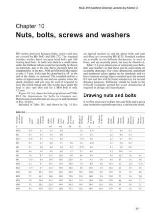
  • 1. ISO metric precision hexagon bolts, screws and nuts are covered by BS 3643 and ISO 272. The standard includes washer faced hexagon head bolts and full bearing head bolts. In both cases there is a small radius under the bolthead which would not normally be shown on drawings, due to its size, but is included here for completeness of the text. With an M36 bolt, the radius is only 1.7 mm. Bolts may be chamfered at 45° at the end of the shank, or radiused. The rounded end has a radius of approximately one and one quarter times the shank diameter and can also be used if required to draw the rolled thread end. The washer face under the head is also very thin and for a M36 bolt is only 0.5 mm. Figure 10.1(a) shows the bolt proportions and Table 10.1 the dimensions for bolts in common use. Dimensions of suitable nuts are also given and illustrated in Fig. 10.1(b). Included in Table 10.1 and shown in Fig. 10.1(c) are typical washers to suit the above bolts and nuts and these are covered by BS 4320. Standard washers are available in two different thicknesses, in steel or brass, and are normally plain, but may be chamfered. Table 10.1 gives dimensions of commonly used bolts, nuts and washers so that these can be used easily on assembly drawings. For some dimensions maximum and minimum values appear in the standards and we have taken an average figure rounded up to the nearest 0.5 mm and this will be found satisfactory for normal drawing purposes. Reference should be made to the relevant standards quoted for exact dimensions if required in design and manufacture. Drawing nuts and bolts It is often necessary to draw nuts and bolts and a quick easy method is required to produce a satisfactory result. Chapter 10 Nuts, bolts, screws and washers Table 10.1 D A/C A/F Df H T t M1.6 0.35 1.1 3.5 3.0 1.0 1.25 1.7 4.0 0.3 M2 0.4 1.4 4.5 4.0 1.5 1.5 2.2 5.0 0.3 M2.5 0.45 1.9 5.5 5.0 1.75 2.0 2.7 6.5 0.5 M3 0.5 2.3 6.0 5.5 5.0 2.0 2.25 3.2 7.0 0.5 M4 0.7 3.0 8.0 7.0 6.5 2.75 3.0 4.3 9.0 0.8 M5 0.8 3.9 9.0 8.0 7.5 3.5 4.0 5.3 10.0 1.0 M6 1.0 4.7 11.5 10.0 9.0 4.0 5.0 6.4 12.5 1.6 0.8 M8 1.25 6.4 15.0 13.0 12.0 5.5 6.5 5.0 8.4 17 1.6 1.0 M10 1.5 8.1 19.5 17.0 16.0 7.0 8.0 6.0 10.5 21 2.0 1.25 M12 1.75 9.7 21.5 19.0 18.0 8.0 10.0 7.0 13.0 24 2.5 1.6 M16 2.0 13.5 27.0 24.0 23.0 10.0 13.0 8.0 17.0 30 3.0 2.0 M20 2.5 16.7 34.0 30.0 29.0 13.0 16.0 9.0 21.0 37 3.0 2.0 M24 3.0 20.0 41.5 36.0 34.5 15.0 19.0 10.0 25.0 44 4.0 2.5 M30 3.5 25.5 52.0 46.0 44.5 19.0 24.0 12.0 31.0 56 4.0 2.5 M36 4.0 31.0 62.5 55.0 53.5 23.0 29.0 14.0 37.0 66 5.0 3.0 Nominal sizethread diameter Thread pitch Minor diameter ofthread Width across corners Width across flats Diameter ofwasher face Heightof bolthead Thickness ofnormal nut Thickness ofthinnut Washer inside diameter Washer outside diameter Washer thickness FormA Washer thickness FormB MCE 310 (Machine Drawing) Lectures by Kilanko O. 77
  • 2. Nuts and bolts are not normally drawn on detail drawings unless they are of a special type. They are shown on assembly drawings and, provided they are standard stock sizes, are called up in parts lists and schedules. A description of the head, the thread and the length being generally sufficient. Templates are available for drawing nuts and bolts and can be recommended for their time saving advantages. It is conventional drawing practice to show, as first choice, nuts and bolts in the across corners position if a single view only is illustrated since this is instantly recognizable. Approximate construction for nuts and bolts (Figs 10.2 and 10.3) Stage 1 1 Draw a circle in the plan position, 2D in diameter, where D is equal to the thread size. In this example let us assume that the thread size is M20. 2 Draw a hexagon inside the 40 mm diameter circle and inside the hexagon draw another circle tangential to the hexagon on the six sides. This circle is the projection of the chamfer which can be seen on the front elevation. 3 the nut thickness is 0.8D. Project the four corners of the hexagon to the front elevation. 4 Project three corners of the hexagon in the end elevation and note, that the width of the end elevation is given by dimension W. 5 Line in the projected diameter of the chamfer circle and the base in the front elevation. 6 As an approximation, draw a radius to show the chamfer on the front elevation. The radius should equal the thread size D. 7 Add the female convention to the plan view. (b) Precision nuts and thin nuts A/F D A/C T t (a) Hexagon head precision bolts Rolled thread end Full bearing head (c) Bright washers d1 d2 Form A Form B SS Chamfer optional 30° Hexagon head washer faced H Df Length D A/F A/C 11 4 D Fig. 10.1 Proportions of bolts, nuts and washers. A/C means across corners. A/F means across flats. W 0.8D D D W 2D Fig. 10.2 Stage 1 MCE 310 (Machine Drawing) Lectures by Kilanko O. 78
  • 3. Stage 2 1 The projection of the curve on the chamfered faces of the hexagon that lie at an angle would produce ellipses in the front elevation. In their place we usually show small circular arcs, their radii can be found by trial, but are approximately 0.25D. 2 The end elevation of the nut has square corners and the projection of the corner which coincides with the centre line terminates at the bottom of the chamfer curve. 3 Complete the view by drawing circular arcs on the two chamfered faces. Find by trial, the radius of an arc which will touch the top of the nut and the projection lines from the corner in the front elevation. Reference to Fig. 10.1a and b will show that the constructions in Fig. 10.2 and Fig. 10.3 can be used for the bolthead and locknut where proportions for thickness can be approximated to 0.7D and 0.5D. For exact dimensions however, please refer to Table 10.1. Socket head screws manufactured to BS EN ISO 4762 and BS 3643-2 It is often required to draw these screws and although the head type and the length are generally quoted in parts lists it is necessary to know the proportions of the head. Dimensions follow for each of the most commonly used screws. Before specifying screws it is advisable to consult a manufacturers list for availability. In the interest of standardization and economy, designers are urged to use stock lengths wherever possible and standard lengths of screws include the following; 3, 4, 5, 6, 8, 10, 12, 16, 20, 25, 30, 35, 40, 45, 50, 55, 60, 65, 70, 75, 80, 90, 100, 110, 120, 130, 140, 150, 160, 170, 180, 190, and 200 mm. If lengths over 200 mm are required, then increments of 20 mm are the preferred ISO lengths. It should be understood that not all diameters of screw are available in the above lengths. For example, the range of lengths for an M3 screw lies between 5 and 35 mm, for an M10 screw between 12 and 100 mm for one particular type of head. The same range will also not cover different types of head, hence the necessity to check stock lists. ISO metric socket cap screws Dimensions in Table 10.2 These screws are distinguished by square knurling on the heads. Generally, the lengths of standard screws increase in increments of 5 mm and 10 mm, but the exact range should be checked from the manufacturers catalogue. Fig. 10.3 Stage 2 Table 10.2 Nominal size D M3 M4 M5 M6 M8 M10 M12 M16 M20 Head diameter A 5.5 7 8.5 10 13 16 18 24 30 Head depth H 3 4 5 6 8 10 12 16 20 Key engagement K 1.3 2 2.7 3.3 4.3 5.5 6.6 8.8 10.7 Socket size J 2.5 3 4 5 6 8 10 14 17 Fig. 10.4 ISO metric hexagon socket shoulder screws. Dimensions in Table 10.3 A D K H Screw length Thread length J ISO metric hexagon socket shoulder screws Dimensions in Table 10.3 Table 10.3 Nominal shoulder diameter B 6 8 10 12 16 Head diameter A 10 13 16 18 24 Head height H 4.5 5.5 7 8 10 Socket size J 3 4 5 6 8 Screw thread diameter D M5 M6 M8 M10 M12 Nominal thread length Lt 9.75 11.25 13.25 16.4 18.4 Key engagement K 2.45 3.3 4.15 4.92 6.62 Fig. 10.5 ISO metric hexagon socket button head screws. Dimensions in Table 10.4 J Lt D B LH K A MCE 310 (Machine Drawing) Lectures by Kilanko O. 79
  • 4. ISO metric hexagon socket button head screws Dimensions in Table 10.4 and the minimum head angle of 90°. The minimum head size is controlled by a minimum head diameter, the maximum head angle of 92° and a flushness tolerance. The edge of the head may be flat, as shown in Fig. 10.8, or rounded but not sharp edged (see below). Table 10.4 Nominal size D M3 M4 M5 M6 M8 M10 M12 Head diameter A 5.5 7.5 9.5 10.5 14 18 21 Head depth H 1.6 2.1 2.7 3.2 4.3 5.3 6.4 Key engagement K 2 2.5 3 4 5 6 8 Socket size J 1.04 1.3 1.56 2.08 2.6 3.12 4.16 Fillet radius F-minimum 0.1 0.2 0.2 0.25 0.4 0.4 0.6 da-maximum 3.6 4.7 5.7 6.8 9.2 11.2 14.2 S 0.38 0.38 0.5 0.8 0.8 0.8 0.8 Fig. 10.6 LS D da FK H A J ISO metric socket countersunk head screws Dimensions in Table 10.5 The basic requirement for countersunk head screws is that the head should fit into a countersunk hole with as great a degree of flushness as possible. Fig. 10.7 and Table 10.5 give dimensions. To achieve this it is necessary for both the head of the screw and the countersunk hole to be controlled within prescribed limits. The maximum or design size of the head is controlled by a theoretical diameter to a sharp corner Table 10.5 Nominal size D M3 M4 M5 M6 M8 M10 M12 M16 M20 Head diameter A – maximum 6.72 8.96 11.2 13.44 17.92 22.4 26.88 33.6 40.32 B – minimum 5.82 7.78 9.78 11.73 15.73 19.67 23.67 29.67 35.61 Head depth H 1.86 2.48 3.1 3.72 4.96 6.2 7.44 8.8 10.16 Socket size J 2 2.5 3 4 5 6 8 10 12 Key engagement K 1.05 1.49 1.86 2.16 2.85 3.60 4.35 4.89 5.49 Fillet radius F – minimum 0.1 0.2 0.2 0.25 0.4 0.4 0.6 0.6 0.8 da – maximum 3.4 4.5 5.5 6.6 9 11 14 18 22 Fig. 10.7 90° B A K H Lt F L D da Sharp corners removed Flushness tolerance Maximum profile Minimum profile 92° Min. Head Dia. Theoretical sharp 90° Fig. 10.8 ISO metric hexagon socket set screws. Dimensions in Table 10.6 ISO metric hexagon socket set screws Dimensions in Table 10.6 These screws are available with a variety of pointed ends. In all cases the overall length includes the chamfer at the socket end and the point. J D L K MCE 310 (Machine Drawing) Lectures by Kilanko O. 80
  • 5. ‘screws’ applies to products which are threaded up to the head or having an unthreaded portion of the shank. The length of the thread is defined as the distance from the end of the screw, and this includes any chamfer, radius or cone point, to the leading face of the nut which has been screwed as far as possible onto the screw by hand. Note on the illustrations which follow that in the case of the countersunk head types of screw, the length of the screw includes the countersunk part of the head. For pan and cheese head screws, the screw length does not include the head. The Standard should be consulted for manufacturing dimensional tolerances, also concentricity tolerances for the heads of the screws. The illustrations which follow show each of the screws and tables are also given showing the dimensions of regularly used sizes. The sizes quoted in the tables are for screws manufactured in steel. Standard screws are also available in brass but generally the range is not quite so extensive. For all of the machine screws illustrated here, the countersunk head types have an included angle of 90°. ‘Posidriv’ machine screws, countersunk and raised countersunk head Dimensions in Table 10.7 Table 10.6 Nominal size D M3 M4 M5 M6 M8 M10 M12 M16 M20 Socket size J 1.5 2 2.5 3 4 5 6 8 10 Key engagement K 1.2 1.6 2 2.4 3.2 4 4.8 6.4 8 Dog point diameter P 2 2.5 3.5 4.5 6 7 9 12 15 Dog point length Q 0.88 1.12 1.38 1.62 2.12 2.62 3.12 4.15 5.15 Cup point and ‘W’ point diameter C 1.4 2 2.5 3 5 6 8 10 14 Note: The cone point angle shown as Y° is generally 118° for short screws and 90° for longer lengths. Y° P Q (b)(a) 90° C 90° 118° C (d)(c) Fig. 10.9 (a) Cone point (b) Dog point (c) W point (d) Cup point Fig. 10.10 Typical GKN socket screws and wrench d L H D Fig. 10.11 Countersunk head d D H L Machine screws Head shapes for machine screws have been rationalized in BS EN ISO 1580 and BS EN ISO 7045. For the purpose of this British Standard, the generic term Fig. 10.12 Raised countersunk head MCE 310 (Machine Drawing) Lectures by Kilanko O. 81
  • 6. ‘Posidriv’ machine screws, pan head Dimensions in Table 10.8 Table 10.7 Diameter Dia of head Depth of head Driver Length d D H no. L M2 4.40 1.20 1 4 5 6 8 10 12 M2.5 5.50 1.50 1 5 6 8 10 12 16 20 25 M3 6.30 1.65 1 5 6 8 10 12 16 20 25 M3.5 7.35 1.93 2 6 8 10 12 16 20 25 30 M4 8.40 2.20 2 6 8 10 12 16 20 25 30 M5 10.00 2.50 2 6 8 10 12 16 20 25 30 35 40 45 50 M6 12.00 3.00 3 10 12 16 20 25 30 35 40 45 50 55 60 M8 16.00 4.00 4 12 16 20 25 30 40 50 60 M10 20.00 5.00 4 16 20 25 30 40 50 60 Slotted machine screws, countersunk and raised countersunk head Dimensions in Table 10.9 Table 10.8 Diameter Dia of head Depth of head Driver Length d D H no. L M2 4.00 1.60 1 4 5 6 8 10 12 M2.5 5.00 1.75 1 5 6 8 10 12 16 20 25 M3 6.00 2.10 1 5 6 8 10 12 16 20 25 M3.5 7.00 2.45 2 6 8 10 12 16 20 25 30 M4 8.00 2.80 2 5 6 8 10 12 16 20 25 30 M5 10.00 3.50 2 6 8 10 12 16 20 25 30 35 40 45 50 M6 12.00 4.20 3 10 12 16 20 25 30 35 40 45 50 55 60 M8 16.00 5.60 4 16 20 25 30 40 50 M10 20.00 7.00 4 20 25 30 40 H L D d Fig. 10.13 L H D d D d H L Fig. 10.14 Countersunk head Fig. 10.15 Raised countersunk head MCE 310 (Machine Drawing) Lectures by Kilanko O. 82
  • 7. Slotted machine screws, cheese head Dimensions in Table 10.11 Table 10.9 Diameter Dia of head Depth of head Length d D H L M2 4.40 1.20 5 6 8 10 12 M2.5 5.50 1.50 5 6 8 10 12 16 20 25 M3 6.30 1.65 5 6 8 10 12 16 20 25 30 35 40 45 50 M3.5 7.35 1.93 5 6 8 10 12 16 20 25 30 35 40 45 50 60 M4 8.40 2.20 5 6 8 10 12 16 20 25 30 35 40 45 50 60 70 M5 10.00 2.50 6 8 10 12 16 20 25 30 35 40 45 50 60 70 80 M6 12.00 3.00 8 10 12 16 20 25 30 35 40 45 50 60 70 80 90 M8 16.00 4.00 10 12 16 20 25 30 35 40 45 50 60 70 80 90 M10 20.00 5.00 16 20 25 30 35 40 45 50 55 60 70 80 90 Slotted machine screws, pan head Dimensions in Table 10.10 Fig. 10.16 D d LH Table 10.10 Diameter Dia of head Depth of Length d D head H L M2 4.00 1.20 4 5 6 8 10 12 M2.5 5.00 1.50 5 6 8 10 12 16 20 25 M3 6.00 1.80 5 6 8 10 12 16 20 25 30 35 40 45 50 M3.5 7.00 2.10 6 8 10 12 16 20 25 30 35 40 45 50 M4 8.00 2.40 5 6 8 10 12 16 20 25 30 35 40 45 50 M5 10.00 3.00 6 8 10 12 16 20 25 30 35 40 45 50 55 60 70 80 M6 12.00 3.60 8 10 12 16 20 25 30 35 40 45 50 55 60 70 80 M8 16.00 4.80 10 12 16 20 25 30 40 50 60 70 80 90 M10 20.00 6.00 16 20 25 30 40 50 60 70 Fig. 10.17 LH d D MCE 310 (Machine Drawing) Lectures by Kilanko O. 83
  • 8. Machine screw nuts A range of machine screw nuts is covered by BS EN ISO 1580 and BS EN ISO 7045 and these nuts are manufactured in two different patterns, square and hexagon. The table shows typical nuts for use with the screws previously described. Table 10.11 Diameter Dia of head Depth of Length d D head H L M2 3.80 1.30 3 4 5 6 8 10 12 16 20 25 M2.5 4.50 1.60 5 6 8 10 12 16 20 25 30 M3 5.50 2.00 4 5 6 8 10 12 16 20 25 30 35 40 45 50 M3.5 6.00 2.40 5 6 8 10 12 16 20 25 30 35 40 45 50 60 70 M4 7.00 2.60 5 6 8 10 12 16 20 25 30 35 40 45 50 60 70 M5 8.50 3.30 6 8 10 12 16 20 25 30 35 40 45 50 60 70 80 90 M6 10.00 3.90 8 10 12 16 20 25 30 35 40 45 50 60 70 80 90 M8 13.00 5.00 10 12 16 20 25 30 35 40 45 50 60 70 80 90 M10 16.00 6.00 16 20 25 30 35 40 45 50 60 70 80 90 Table 10.12 Machine screw nuts, pressed type, square and hexagonal Nominal size Width across Width across corners e Thickness of nut d flats s Square Hexagon m M2 4.0 5.7 4.6 1.2 M2.5 5.0 7.1 5.8 1.6 M3 5.5 7.8 6.4 1.6 M3.5 6.0 8.5 6.9 2.0 M4 7.0 9.9 8.1 2.0 M5 8.0 11.3 9.2 2.5 M6 10.0 14.1 11.5 3.0 M8 13.0 18.4 15.0 4.0 M10 17.0 24.0 19.6 5.0 Fig. 10.18 Square nut m d s e Wing nuts Figure 10.20 shows the dimensions of preferred sizes of wing nuts manufactured in brass or malleable iron by a hot stamping or casting process. m s e d Fig. 10.19 Hexagon nut Fig. 10.20 (Sizes are in Table 16.13) E G D F Thread size Alternative wing shape A H J B C Small rad in corner Table 10.13 Thread size A B C D E F G H J M3 9 6.5 7 13.5 22 19 3.5 2.5 1.5 M4 and M5 10 8 9 15 25.5 19 4 2.5 1.5 M6 13 9.5 11 18 30 19 5 2.5 1.5 M8 16 12 13 23 38 19 6.5 3 2.5 M10 17.5 14 14 25.5 44.5 19 7 5 3 M12 19 16 15 28.5 51 25.5 8 5 3 M16 25.5 20.5 19 36.5 63.5 32 10 6.5 5 An alternative wing nut is available in brass or malleable iron and manufactured by cold forging. MCE 310 (Machine Drawing) Lectures by Kilanko O. 84