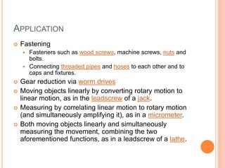
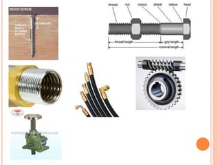
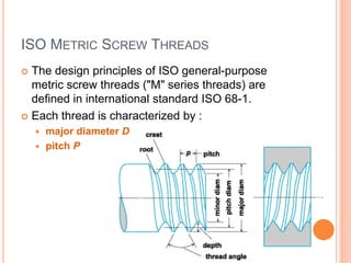
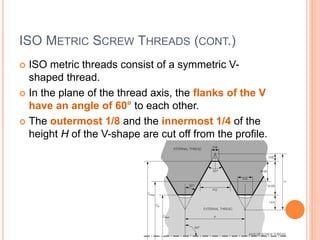
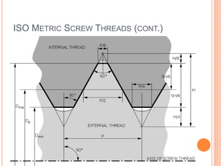
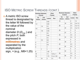
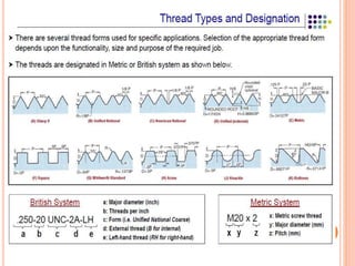
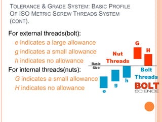
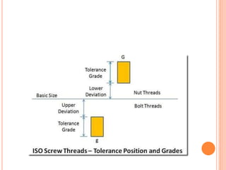
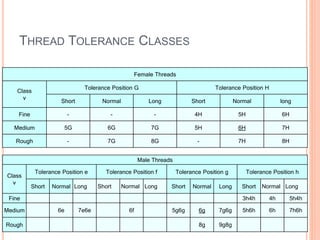
SCREW THREAD MEASUREMENT -
MATRIX
Workshop Technology
AFTER COMPLETING THIS TOPIC, STUDENTS
SHOULD BE ABLE TO:
 Describe various types of thread standards.
 Illustrate screw thread profile.
 Identify screw thread standard.
Introduction & definition
 A screw thread, is a helical structure used to convert
between rotational and linear movement or force.
 A screw thread is a ridge wrapped around
a cylinder or cone in the form of a helix, with the former
being called a straight thread and the latter called
a tapered thread.
 There are many systems for specifying the dimensions
of screws, but in much of the world the ISO metric screw
thread preferred series has displaced the many older
systems.
 Other relatively common systems include the British
Standard Whitworth, BA system (British Association),
and the SAE Unified Thread Standard.
APPLICATION
 Fastening
 Fasteners such as wood screws, machine screws, nuts and
bolts.
 Connecting threaded pipes and hoses to each other and to
caps and fixtures.
 Gear reduction via worm drives
 Moving objects linearly by converting rotary motion to
linear motion, as in the leadscrew of a jack.
 Measuring by correlating linear motion to rotary motion
(and simultaneously amplifying it), as in a micrometer.
 Both moving objects linearly and simultaneously
measuring the movement, combining the two
aforementioned functions, as in a leadscrew of a lathe.
APPLICATION
 In all of these applications, the screw thread has
two main functions:
 It converts rotary motion into linear motion.
 It prevents linear motion without the corresponding
rotation.
TYPES OF THREAD
 ISO Metric Screw Threads
 British Standard Screw Threads
 British Association Screw Threads (BA)
 Unified Threads Standard
ISO METRIC SCREW THREADS
 The design principles of ISO general-purpose
metric screw threads ("M" series threads) are
defined in international standard ISO 68-1.
 Each thread is characterized by :
 major diameter D
 pitch P
ISO METRIC SCREW THREADS (CONT.)
 ISO metric threads consist of a symmetric V-
shaped thread.
 In the plane of the thread axis, the flanks of the V
have an angle of 60° to each other.
 The outermost 1/8 and the innermost 1/4 of the
height H of the V-shape are cut off from the profile.
ISO METRIC SCREW THREADS (CONT.)
 In an external (male) thread (e.g., on a bolt), the
major diameter Dmaj and the minor
diameter Dmin define maximum dimensions of the
thread.
 This means that the external thread must end flat
at Dmaj, but can be rounded out below the minor
diameterDmin.
 Conversely, in an internal (female) thread (e.g., in
a nut), the major and minor diameters
are minimum dimensions, therefore the thread
profile must end flat at Dmin but may be rounded out
beyond Dmaj.
ISO METRIC SCREW THREADS (CONT.)
 A metric ISO screw
thread is designated by
the letter M followed by
the value of the
nominal
diameter D (Dmaj ) and
the pitch P, both
expressed in
millimetres and
separated by the
multiplication
sign, × (e.g., M8×1.25)
BRITISH STANDARD SCREW THREADS
 British Standard Whitworth (BSW) is one of a
number of imperial unit based screw
thread standards which use the same bolt heads
and nut hexagonal sizes,
 The others being British Standard Fine
thread (BSF) and British Standard Cycle.
 These three are collectively called Whitworth
threads.
BRITISH STANDARD SCREW THREADS (CONT.)
BRITISH ASSOCIATION SCREW THREADS (BA)
 British Association or BA screw threads are a
largely obsolete set of small screw threads, the
largest being 0BA at 6 mm diameter.
 They were, and to some extent still are, used for
miniature instruments and modelling.
 BA threads are still used in some precision
instruments, such as optics and moving-coil meters,
relays etc.
 A 2BA thread is used to connect the head of
a dart to its shaft — as such, it is one of the few
common uses of this thread in North America.
BRITISH ASSOCIATION SCREW THREADS (BA)
(CONT.)
BRITISH ASSOCIATION SCREW THREADS (BA)
(CONT.)
UNIFIED THREADS STANDARD (UTS)
 The Unified Thread Standard (UTS) defines
a standard thread form and series—along with
allowances, tolerances, and designations—
for screw threads commonly used in the United
States and Canada.
 It has the same 60° profile as the ISO metric
screw thread used in the rest of the world, but the
characteristic dimensions of each UTS thread
(outer diameter and pitch) were chosen as an
inch fraction rather than a round millimeter value.
 The UTS is currently controlled by ASME/ANSI in
the United States.
UNIFIED THREADS STANDARD (UTS) (CONT.)
A diagram of an ISO metric or Unified thread, showing dimensions relative to the pitch (P) and
thread height (H). Note that while different standards, ISO and UTS share the same geometry,
but not absolute dimensions. Also shown is the location rounding permissible in internal (dark
grey, top) and external (light grey, bottom) threads.
Key
P: Pitch
H: Thread height
Dmaj: Major diameter
Dmin: Minor diameter
Dp: Effective pitch diameter
TOLERANCE & GRADE SYSTEM: BASIC PROFILE
OF ISO METRIC SCREW THREADS SYSTEM
 The basic profile is the theoretical profile of the
thread.
 An essential principle is that the actual profiles of
both the nut and bolt threads must never cross or
transgress the theoretical profile.
 So bolt threads will always be equal to, or
smaller than, the dimensions of the basic profile.
Nut threads will always be equal to, or greater
than, the basic profile. To ensure this in practice,
tolerances and allowances are applied to the basic
profile.
TOLERANCE & GRADE SYSTEM: BASIC PROFILE
OF ISO METRIC SCREW THREADS SYSTEM
(CONT).
 Bolt threads usually have a gap between the basic
and actual thread profiles.
 This gap is called the allowance with inch-based
threads and the fundamental deviation with metric
threads.
 The tolerance is subsequently applied to the thread.
TOLERANCE & GRADE SYSTEM: BASIC PROFILE
OF ISO METRIC SCREW THREADS SYSTEM
(CONT).
 The method of applying manufacturing tolerances
to the internal and external threads such that they
fit together is by use of the tolerance class which
is a combination of the tolerance grade ( a
number) and a tolerance position ( a letter).
 For the internal threads(nuts) the letter is upper
case and for the external threads(bolt) the letter
is lower case.
 Therefore H6 is a tolerance grade for a Internal
(female) thread and g6 is a tolerance grade for a
External (male) thread.
TOLERANCE & GRADE SYSTEM: BASIC PROFILE
OF ISO METRIC SCREW THREADS SYSTEM
(CONT).
 The tolerance band positions relative to the basic
zero size are illustrated in the figure below:
TOLERANCE & GRADE SYSTEM: BASIC PROFILE
OF ISO METRIC SCREW THREADS SYSTEM
(CONT).
 The (fundamental)tolerance position is defined as
the nearest end of the tolerance band to the zero
tolerance position (Dead size position).
 These positions are identified as EI for the internal
thread and es for the external thread.
TOLERANCE & GRADE SYSTEM: BASIC PROFILE
OF ISO METRIC SCREW THREADS SYSTEM
(CONT).
 An external metric thread may be designated as follows:
 Pitch Outside
Nominal Diameter Diameter
Metric Size Pitch Tolerance Tolerance
M 6 X 0.75 - 5g 6g
 The thread fit between mating parts is indicated by
internal thread designation followed by the external
thread tolerance:
 M 20 X 2 - 6H/5g 6g
TOLERANCE & GRADE SYSTEM: BASIC PROFILE
OF ISO METRIC SCREW THREADS SYSTEM
(CONT).
 For external threads(bolt):
 e indicates a large allowance
 g indicates a small allowance
 h indicates no allowance
 For internal threads(nuts):
 G indicates a small allowance
 H indicates no allowance
THREAD TOLERANCE CLASSES
Female Threads
Class
v
Tolerance Position G Tolerance Position H
Short Normal Long Short Normal long
Fine - - - 4H 5H 6H
Medium 5G 6G 7G 5H 6H 7H
Rough - 7G 8G - 7H 8H
Male Threads
Class
v
Tolerance Position e Tolerance Position f Tolerance Position g Tolerance Position h
Short Normal Long Short Normal Long Short Normal Long Short Normal Long
Fine 3h4h 4h 5h4h
Medium 6e 7e6e 6f 5g6g 6g 7g6g 5h6h 6h 7h6h
Rough 8g 9g8g
SCREW THREAD GAUGING
 A thread pitch gauge, also known as a screw pitch
gauge or pitch gauge, is used to measure the pitch or
lead of a screw thread.
 Thread pitch gauges are used as a reference tool in
determining the pitch of a thread that is on a screw or in
a tapped hole.
 This tool is not used as a precision measuring
instrument.
 This device allows the user to determine the profile of
the given thread and quickly categorize the thread by
shape and pitch.
 This device also saves time, in that it removes the need
for the user to measure and calculate the thread pitch of
the threaded item.
SCREW THREAD GAUGING
Various Size of Screw Thread Gauge
THREAD GAUGING SYSTEM
 In the thread gauges system, the limit type is most common.
Thread of workpiece is ensured by controlling the GO and NOT
GO limit.
 The types of limit thread gauges systems are broadly divided into :
 ISO class and
 conventional class 1,2,3.
THREAD GAUGING SYSTEM
 Differences between ISO Gauge System & Class 1, 2, 3 System
listed below:
 Pass/Fail assessment of a NOT GO gauge for the ISO class
gauge system has been set as not be screwed in more than two
revolutions.
 For class 1,2,3 gauge system it is not to be screwed in more than
two revolutions, included two revolutions.
THANK YOU
Screw Thread Measurement -Matrix

Screw Thread Measurement -Matrix.pptx

  • 1.
    SCREW THREAD MEASUREMENT- MATRIX Workshop Technology
  • 2.
    AFTER COMPLETING THISTOPIC, STUDENTS SHOULD BE ABLE TO:  Describe various types of thread standards.  Illustrate screw thread profile.  Identify screw thread standard.
  • 3.
    Introduction & definition A screw thread, is a helical structure used to convert between rotational and linear movement or force.  A screw thread is a ridge wrapped around a cylinder or cone in the form of a helix, with the former being called a straight thread and the latter called a tapered thread.  There are many systems for specifying the dimensions of screws, but in much of the world the ISO metric screw thread preferred series has displaced the many older systems.  Other relatively common systems include the British Standard Whitworth, BA system (British Association), and the SAE Unified Thread Standard.
  • 5.
    APPLICATION  Fastening  Fastenerssuch as wood screws, machine screws, nuts and bolts.  Connecting threaded pipes and hoses to each other and to caps and fixtures.  Gear reduction via worm drives  Moving objects linearly by converting rotary motion to linear motion, as in the leadscrew of a jack.  Measuring by correlating linear motion to rotary motion (and simultaneously amplifying it), as in a micrometer.  Both moving objects linearly and simultaneously measuring the movement, combining the two aforementioned functions, as in a leadscrew of a lathe.
  • 7.
    APPLICATION  In allof these applications, the screw thread has two main functions:  It converts rotary motion into linear motion.  It prevents linear motion without the corresponding rotation.
  • 8.
    TYPES OF THREAD ISO Metric Screw Threads  British Standard Screw Threads  British Association Screw Threads (BA)  Unified Threads Standard
  • 9.
    ISO METRIC SCREWTHREADS  The design principles of ISO general-purpose metric screw threads ("M" series threads) are defined in international standard ISO 68-1.  Each thread is characterized by :  major diameter D  pitch P
  • 10.
    ISO METRIC SCREWTHREADS (CONT.)  ISO metric threads consist of a symmetric V- shaped thread.  In the plane of the thread axis, the flanks of the V have an angle of 60° to each other.  The outermost 1/8 and the innermost 1/4 of the height H of the V-shape are cut off from the profile.
  • 11.
    ISO METRIC SCREWTHREADS (CONT.)  In an external (male) thread (e.g., on a bolt), the major diameter Dmaj and the minor diameter Dmin define maximum dimensions of the thread.  This means that the external thread must end flat at Dmaj, but can be rounded out below the minor diameterDmin.  Conversely, in an internal (female) thread (e.g., in a nut), the major and minor diameters are minimum dimensions, therefore the thread profile must end flat at Dmin but may be rounded out beyond Dmaj.
  • 12.
    ISO METRIC SCREWTHREADS (CONT.)
  • 13.
    ISO METRIC SCREWTHREADS (CONT.)  A metric ISO screw thread is designated by the letter M followed by the value of the nominal diameter D (Dmaj ) and the pitch P, both expressed in millimetres and separated by the multiplication sign, × (e.g., M8×1.25)
  • 15.
    BRITISH STANDARD SCREWTHREADS  British Standard Whitworth (BSW) is one of a number of imperial unit based screw thread standards which use the same bolt heads and nut hexagonal sizes,  The others being British Standard Fine thread (BSF) and British Standard Cycle.  These three are collectively called Whitworth threads.
  • 16.
    BRITISH STANDARD SCREWTHREADS (CONT.)
  • 17.
    BRITISH ASSOCIATION SCREWTHREADS (BA)  British Association or BA screw threads are a largely obsolete set of small screw threads, the largest being 0BA at 6 mm diameter.  They were, and to some extent still are, used for miniature instruments and modelling.  BA threads are still used in some precision instruments, such as optics and moving-coil meters, relays etc.  A 2BA thread is used to connect the head of a dart to its shaft — as such, it is one of the few common uses of this thread in North America.
  • 18.
    BRITISH ASSOCIATION SCREWTHREADS (BA) (CONT.)
  • 19.
    BRITISH ASSOCIATION SCREWTHREADS (BA) (CONT.)
  • 20.
    UNIFIED THREADS STANDARD(UTS)  The Unified Thread Standard (UTS) defines a standard thread form and series—along with allowances, tolerances, and designations— for screw threads commonly used in the United States and Canada.  It has the same 60° profile as the ISO metric screw thread used in the rest of the world, but the characteristic dimensions of each UTS thread (outer diameter and pitch) were chosen as an inch fraction rather than a round millimeter value.  The UTS is currently controlled by ASME/ANSI in the United States.
  • 21.
    UNIFIED THREADS STANDARD(UTS) (CONT.) A diagram of an ISO metric or Unified thread, showing dimensions relative to the pitch (P) and thread height (H). Note that while different standards, ISO and UTS share the same geometry, but not absolute dimensions. Also shown is the location rounding permissible in internal (dark grey, top) and external (light grey, bottom) threads. Key P: Pitch H: Thread height Dmaj: Major diameter Dmin: Minor diameter Dp: Effective pitch diameter
  • 23.
    TOLERANCE & GRADESYSTEM: BASIC PROFILE OF ISO METRIC SCREW THREADS SYSTEM  The basic profile is the theoretical profile of the thread.  An essential principle is that the actual profiles of both the nut and bolt threads must never cross or transgress the theoretical profile.  So bolt threads will always be equal to, or smaller than, the dimensions of the basic profile. Nut threads will always be equal to, or greater than, the basic profile. To ensure this in practice, tolerances and allowances are applied to the basic profile.
  • 24.
    TOLERANCE & GRADESYSTEM: BASIC PROFILE OF ISO METRIC SCREW THREADS SYSTEM (CONT).  Bolt threads usually have a gap between the basic and actual thread profiles.  This gap is called the allowance with inch-based threads and the fundamental deviation with metric threads.  The tolerance is subsequently applied to the thread.
  • 25.
    TOLERANCE & GRADESYSTEM: BASIC PROFILE OF ISO METRIC SCREW THREADS SYSTEM (CONT).  The method of applying manufacturing tolerances to the internal and external threads such that they fit together is by use of the tolerance class which is a combination of the tolerance grade ( a number) and a tolerance position ( a letter).  For the internal threads(nuts) the letter is upper case and for the external threads(bolt) the letter is lower case.  Therefore H6 is a tolerance grade for a Internal (female) thread and g6 is a tolerance grade for a External (male) thread.
  • 26.
    TOLERANCE & GRADESYSTEM: BASIC PROFILE OF ISO METRIC SCREW THREADS SYSTEM (CONT).  The tolerance band positions relative to the basic zero size are illustrated in the figure below:
  • 27.
    TOLERANCE & GRADESYSTEM: BASIC PROFILE OF ISO METRIC SCREW THREADS SYSTEM (CONT).  The (fundamental)tolerance position is defined as the nearest end of the tolerance band to the zero tolerance position (Dead size position).  These positions are identified as EI for the internal thread and es for the external thread.
  • 28.
    TOLERANCE & GRADESYSTEM: BASIC PROFILE OF ISO METRIC SCREW THREADS SYSTEM (CONT).  An external metric thread may be designated as follows:  Pitch Outside Nominal Diameter Diameter Metric Size Pitch Tolerance Tolerance M 6 X 0.75 - 5g 6g  The thread fit between mating parts is indicated by internal thread designation followed by the external thread tolerance:  M 20 X 2 - 6H/5g 6g
  • 29.
    TOLERANCE & GRADESYSTEM: BASIC PROFILE OF ISO METRIC SCREW THREADS SYSTEM (CONT).  For external threads(bolt):  e indicates a large allowance  g indicates a small allowance  h indicates no allowance  For internal threads(nuts):  G indicates a small allowance  H indicates no allowance
  • 31.
    THREAD TOLERANCE CLASSES FemaleThreads Class v Tolerance Position G Tolerance Position H Short Normal Long Short Normal long Fine - - - 4H 5H 6H Medium 5G 6G 7G 5H 6H 7H Rough - 7G 8G - 7H 8H Male Threads Class v Tolerance Position e Tolerance Position f Tolerance Position g Tolerance Position h Short Normal Long Short Normal Long Short Normal Long Short Normal Long Fine 3h4h 4h 5h4h Medium 6e 7e6e 6f 5g6g 6g 7g6g 5h6h 6h 7h6h Rough 8g 9g8g
  • 32.
    SCREW THREAD GAUGING A thread pitch gauge, also known as a screw pitch gauge or pitch gauge, is used to measure the pitch or lead of a screw thread.  Thread pitch gauges are used as a reference tool in determining the pitch of a thread that is on a screw or in a tapped hole.  This tool is not used as a precision measuring instrument.  This device allows the user to determine the profile of the given thread and quickly categorize the thread by shape and pitch.  This device also saves time, in that it removes the need for the user to measure and calculate the thread pitch of the threaded item.
  • 33.
    SCREW THREAD GAUGING VariousSize of Screw Thread Gauge
  • 34.
    THREAD GAUGING SYSTEM In the thread gauges system, the limit type is most common. Thread of workpiece is ensured by controlling the GO and NOT GO limit.  The types of limit thread gauges systems are broadly divided into :  ISO class and  conventional class 1,2,3.
  • 35.
    THREAD GAUGING SYSTEM Differences between ISO Gauge System & Class 1, 2, 3 System listed below:  Pass/Fail assessment of a NOT GO gauge for the ISO class gauge system has been set as not be screwed in more than two revolutions.  For class 1,2,3 gauge system it is not to be screwed in more than two revolutions, included two revolutions.
  • 40.
    THANK YOU Screw ThreadMeasurement -Matrix