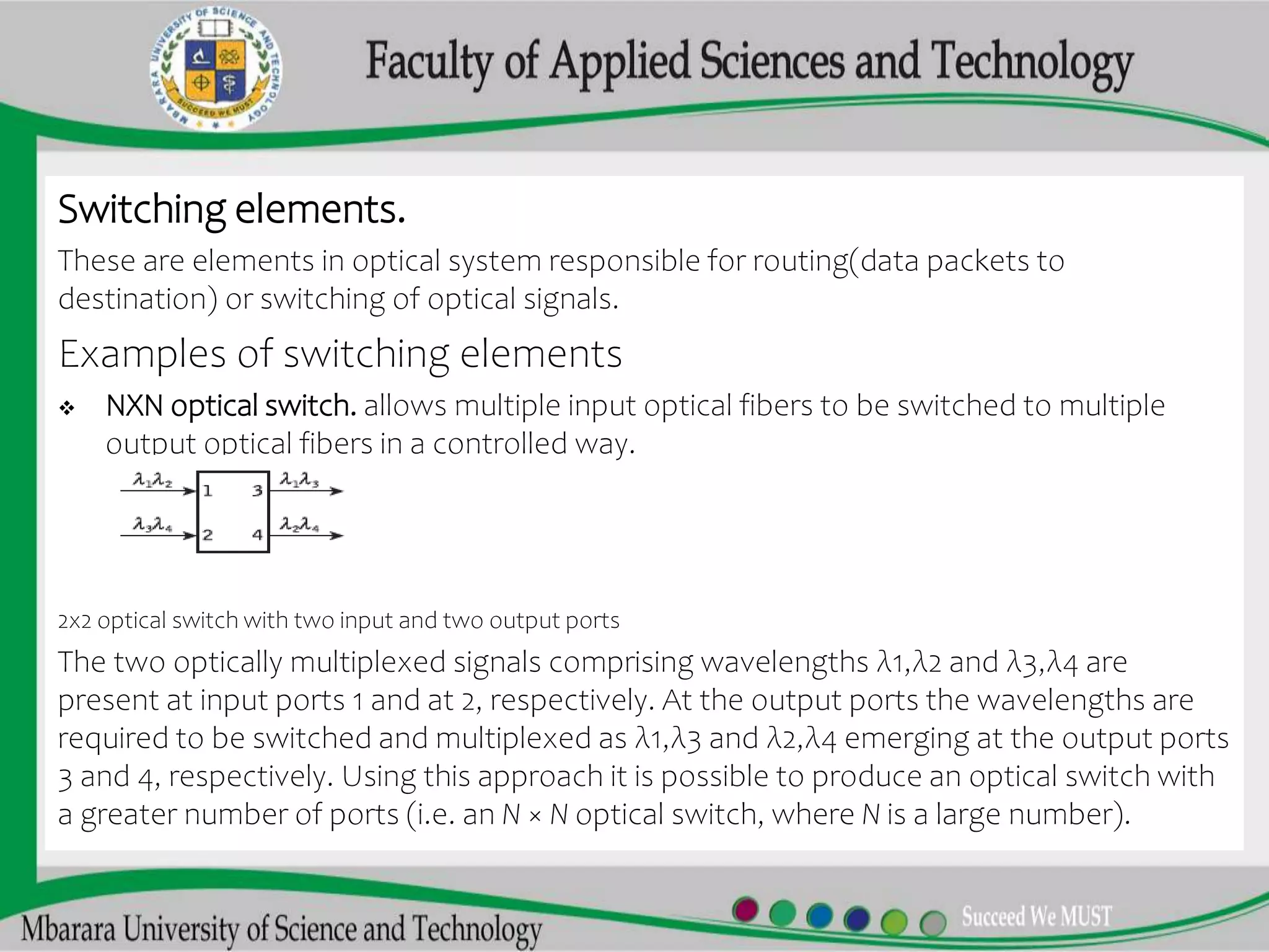
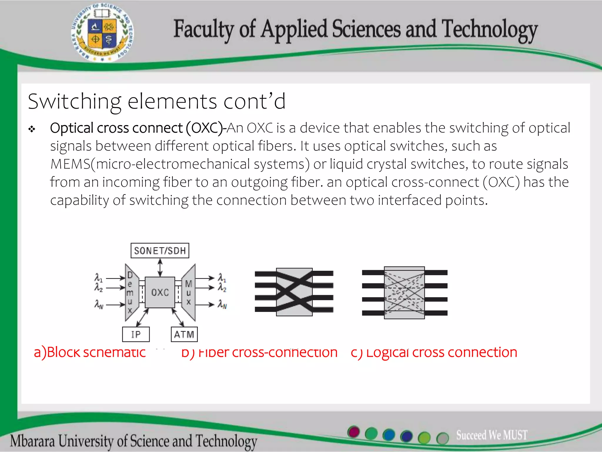
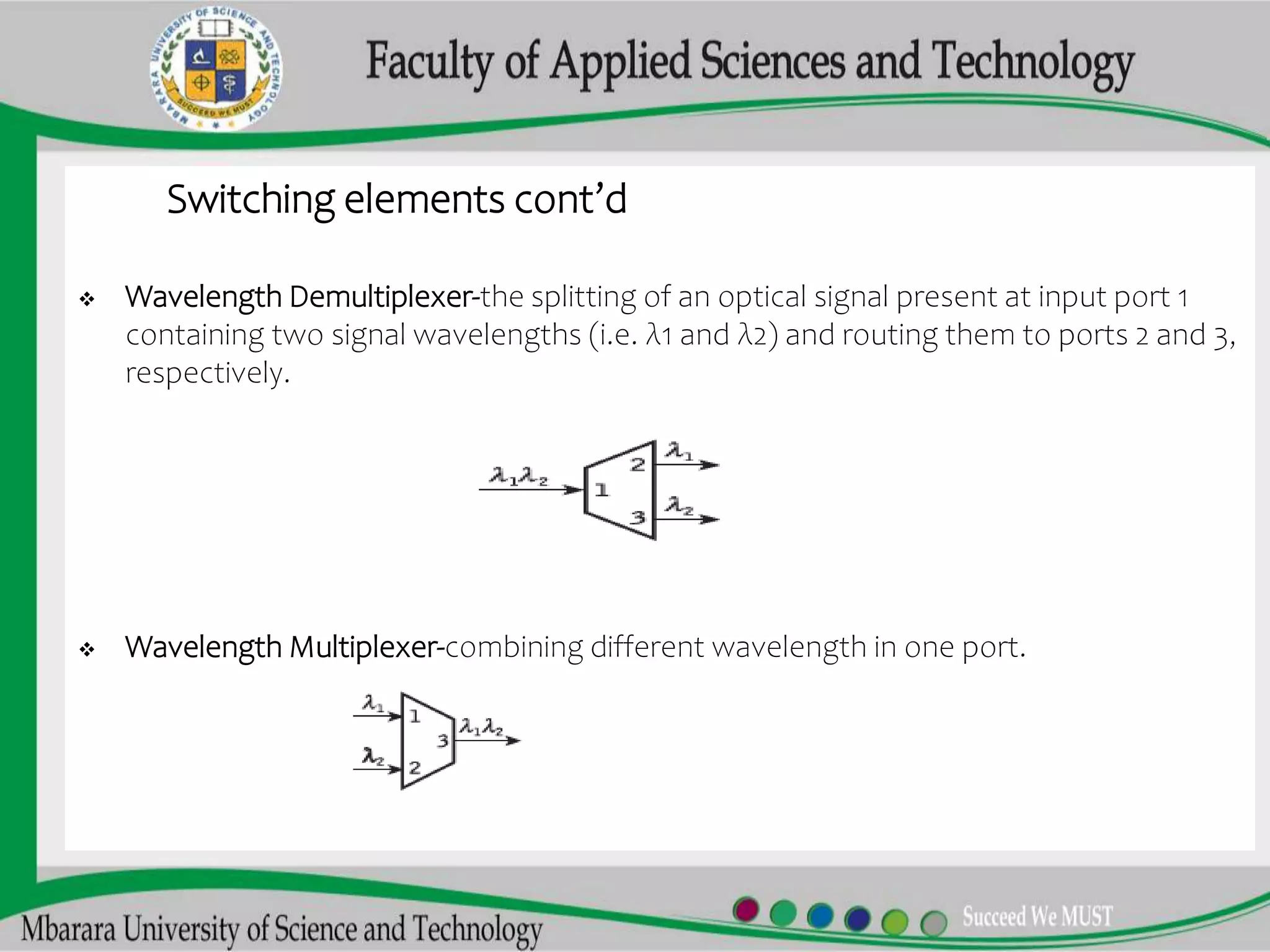
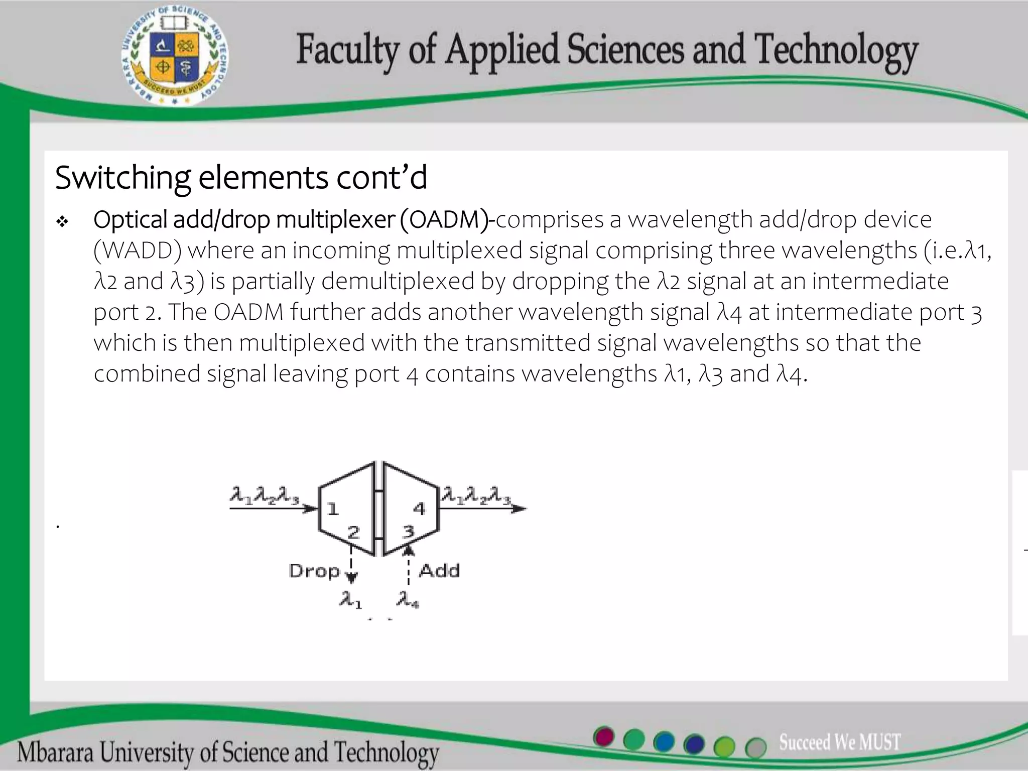
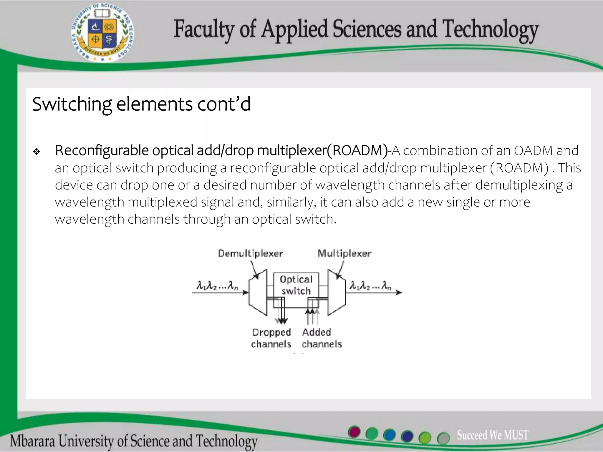
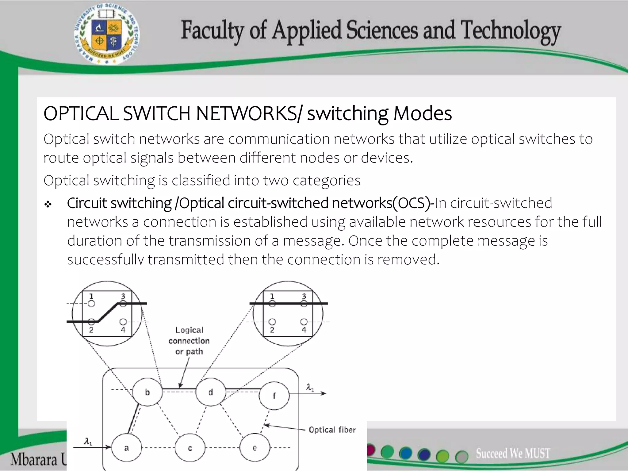
2. OPTICAL SWITCHING
Optical switching is a technology used in telecommunications and networking to
control the flow of optical signals (i.e., light) through a network. It involves the use of
optical switches that can selectively direct light signals from one optical fiber to
another, based on specific criteria such as wavelength or destination address.
Optical switching is an important technology for increasing the capacity and speed
of modern communication networks, as it enables high-bandwidth data transmission
over long distances with minimal signal degradation.
Optical switching mainly occurs at the optical nodes
Optical node and switching elements
In optical communication an optical node element that is responsible for receiving,
transmitting(transceiver), and routing optical signals in an optical network. The
optical network node is usually located at network junction points, where multiple
optical fibers converge or diverge, and it is equipped with various optical switching
elements to perform these functions.
3. Switching elements.
These are elements in optical system responsible for routing(data packets to
destination) or switching of optical signals.
Examples of switching elements
NXN optical switch. allows multiple input optical fibers to be switched to multiple
output optical fibers in a controlled way.
2x2 optical switch with two input and two output ports
The two optically multiplexed signals comprising wavelengths λ1,λ2 and λ3,λ4 are
present at input ports 1 and at 2, respectively. At the output ports the wavelengths are
required to be switched and multiplexed as λ1,λ3 and λ2,λ4 emerging at the output ports
3 and 4, respectively. Using this approach it is possible to produce an optical switch with
a greater number of ports (i.e. an N × N optical switch, where N is a large number).
4. Switching elements cont’d
Optical cross connect (OXC)-An OXC is a device that enables the switching of optical
signals between different optical fibers. It uses optical switches, such as
MEMS(micro-electromechanical systems) or liquid crystal switches, to route signals
from an incoming fiber to an outgoing fiber. an optical cross-connect (OXC) has the
capability of switching the connection between two interfaced points.
a)Block schematic b) Fiber cross-connection c) Logical cross connection
5. A large number of wavelength signals (i.e. λ1, λ2, . . . , λN) can be demultiplexed at
the input ports of an OXC as shown in Figure (a) and then these are internally
connected to the desired output ports where the different wavelength signals are
multiplexed for onward transmission.
The OXC contains N × N optical switching fabric which facilitates either physical or
logical interconnections. Physical interconnection is provided by the fiber switching
capability within the OXC as illustrated (b). In this case optical fibers are switched
and connected to the desired network node. The OXC can also facilitate the logical
wavelength interconnection features as indicated in (c) for multiple wavelength
signals which can be routed to their destination either individually or in a group of
different wavelength signals
6. Switching elements cont’d
Wavelength Demultiplexer-the splitting of an optical signal present at input port 1
containing two signal wavelengths (i.e. λ1 and λ2) and routing them to ports 2 and 3,
respectively.
Wavelength Multiplexer-combining different wavelength in one port.
7. Switching elements cont’d
Optical add/drop multiplexer (OADM)-comprises a wavelength add/drop device
(WADD) where an incoming multiplexed signal comprising three wavelengths (i.e.λ1,
λ2 and λ3) is partially demultiplexed by dropping the λ2 signal at an intermediate
port 2. The OADM further adds another wavelength signal λ4 at intermediate port 3
which is then multiplexed with the transmitted signal wavelengths so that the
combined signal leaving port 4 contains wavelengths λ1, λ3 and λ4.
.
8. Switching elements cont’d
Reconfigurable optical add/drop multiplexer(ROADM)-A combination of an OADM and
an optical switch producing a reconfigurable optical add/drop multiplexer (ROADM) . This
device can drop one or a desired number of wavelength channels after demultiplexing a
wavelength multiplexed signal and, similarly, it can also add a new single or more
wavelength channels through an optical switch.
9. OPTICAL SWITCH NETWORKS/ switching Modes
Optical switch networks are communication networks that utilize optical switches to
route optical signals between different nodes or devices.
Optical switching is classified into two categories
Circuit switching /Optical circuit-switched networks(OCS)-In circuit-switched
networks a connection is established using available network resources for the full
duration of the transmission of a message. Once the complete message is
successfully transmitted then the connection is removed.
10. OCS cont’d
In the above configuration six optical nodes (i.e. a to f) are interconnected and a
requested logical connection or path for optical signal wavelength, λ1, is
established producing a circuit path through network nodes a, b, d and f. Optical
nodes of an OCS network contain optical switches where large multiport optical
switches (i.e. a switching fabric) or an OXC are used to establish connections
between the desired input and output ports.
Optical packet-switched networks(OPS)-In OPS, data is broken up into packets
that are switched between nodes based on their destination address. This
allows for more flexible and efficient use of network resources.
Optical burst switching networks(OBS)-Combining important aspects of optical
circuit switching and optical packet switching results in optical burst switching
(OBS). In OBS networks, data is transmitted in bursts, which are groups of
packets that are sent together. The network uses a control packet, called a
burst header packet (BHP), to set up the network path for each burst. The BHP
contains information such as the source and destination addresses, the burst
length, and the start time of the burst.
Editor's Notes
connection between many users to enable them to communicate with each other. Users can be ring ,mesh,star topology with nodes and fibers in between