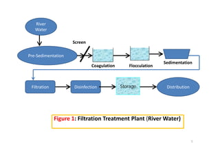
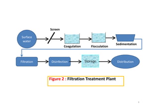
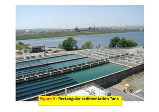
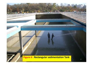
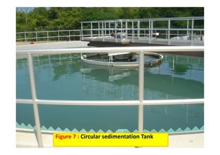
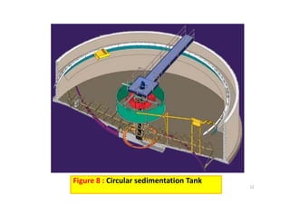
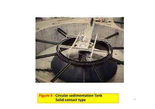
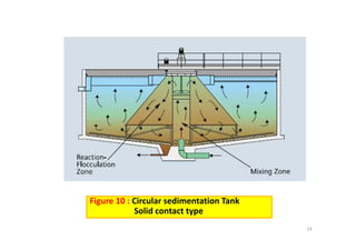
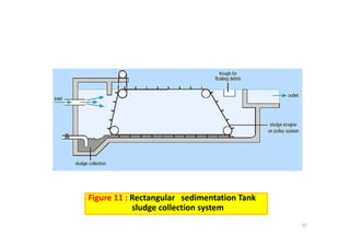
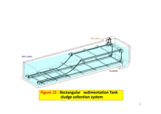
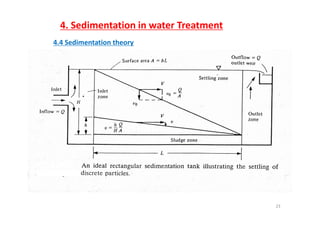
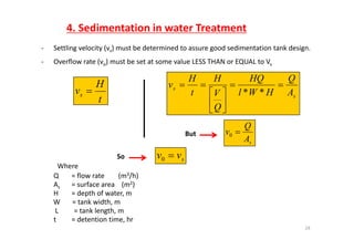
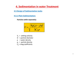
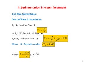
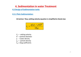
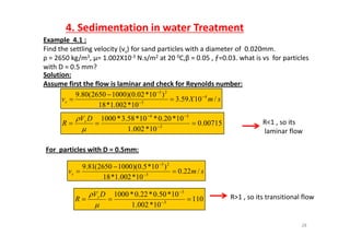
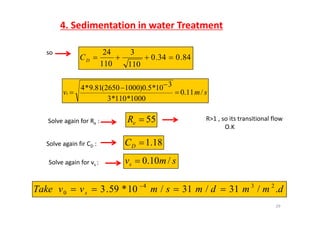
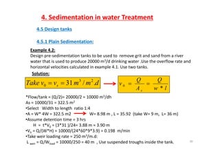
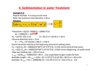
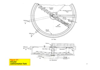
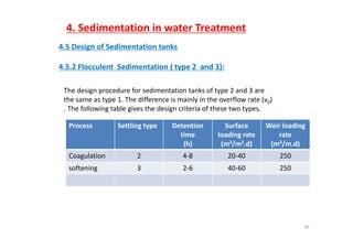
Islamic University of Gaza  ‐Environmental Engineering Department
Water TreatmentWater Treatment
EENV 4331
Lecture 4:   Sedimentation
Dr.   Fahid Rabah
1
4. Sedimentation in water Treatment
4.1 Definition of Sedimentation:
It is the process of removing solid particles heavier than water
by gravity force.
 Particles that will settle within a reasonable period of time
can be removed using a sedimentation tank (also called
clarifiers).
 Sedimentation is used in water treatment at the locations
indicated in Figures 1 through 4.
2
4. Sedimentation in water Treatment
4.2 Applications of sedimentation in water treatment:pp
1. Plain settling ( or pre‐sedimentation) of river surface
water .
2. In filtration treatment plants treating surface water to
removes flocculated solids. The sedimentation tank comes
after the flocculation tank.
3. In Softening treatment plants treating hard water to
removes flocculated solids. The sedimentation tank comes
ft th fl l ti t kafter the flocculation tank.
4. In aeration treatment plant removing iron and manganese
from ground water
3
4. Sedimentation in water Treatment
4.3 Geometry of sedimentation tanks:y
 Sedimentation tanks are either rectangular or circular
tanks.
 Figures 5 to 10 show typical sedimentation tanks used in
water treatment.
4
River
Screen
River 
Water
Pre‐Sedimentation
Screen
Coagulation Flocculation
Sedimentation
DistributionDisinfection StorageFiltration
Figure 1: Filtration Treatment Plant (River Water)
5
Screen
Surface 
water
S di t ti
Coagulation Flocculation
Sedimentation
DistributionDisinfection StorageFiltration
Figure 2 : Filtration Treatment Plant
6
Ground 
WaterWater
Rapid Mixing Flocculation Sedimentation Recarbonation
DistributionDisinfection StorageFiltration
Figure 3: Softening Treatment Plant Single stage  softening
7
Ground 
Water 
well
FiltrationAeration
Distribution
Disinfection Storage
Figure 4 : Aeration  Treatment Plant
( iron and manganese removal plant)( iron and manganese removal plant)
8
9
Figure 5 : Rectangular sedimentation Tank
10
Figure 6 : Rectangular sedimentation Tank
11
Figure 7 : Circular sedimentation Tank
12
Figure 8 : Circular sedimentation Tank
13
Figure 9 : Circular sedimentation Tank
Solid contact type
Figure 10 : Circular sedimentation Tank                  
Solid contact type
14
Solid contact type
Figure 11 : Rectangular   sedimentation Tank                  
sludge collection system
15
sludge collection system
Figure 12 : Rectangular   sedimentation Tank                  
l d ll ti t
16
sludge collection system
Figure 13 : Rectangular   sedimentation Tank                  
l d ll ti t
17
sludge collection system
Figure 14 : Rectangular   sedimentation Tank                  
l d ll ti t
18
sludge collection system
4. Sedimentation in water Treatment
4.3 Theoretical background on Sedimentation
4 3 1 Type of particles :4.3.1 Type of particles :
1) Discrete / individual particle
- Size, velocity constant during the settling
D it 2 000 2 200 k / 3- Density 2,000 – 2,200 kg/m3
2) Flocculent particles
- Size, velocity fluctuates during the settling
- Particles flocculate and grow bigger in size
- Density 1,030 – 1,070 kg/m3
19
Density 1,030 1,070 kg/m
4. Sedimentation in water Treatment
4.3.2 Three classes of particles settling : 
Type 1Type 1
i) Particles settle discretely at a constant velocity
ii) Settle as individual particles and do not flocculate.
iii) E.g. : Sand, grit materialiii) E.g. : Sand, grit material 
iv) Occurs during :
i) Pre‐sedimentation for sand removal
ii) Settling of sand during rapid sand filter cleaning
v) Concentration : very low
20
4. Sedimentation in water Treatment
Type 2
i) Flocculate during sedimentationi) Flocculate during sedimentation
ii) Size constantly changing
iii) Settling velocity is changing
iv) Settling velocity increase with depth and extent of flocculation.
v) Occurs during : 
i) Alum or iron coagulation
vi) Concentration : low
21
4. Sedimentation in water Treatment
Type 3 or Zone 
i) Settle as mass and form a layer – “blanket 
ii) Concentration high (greater than 1000 mg/L)ii) Concentration high (greater than 1000 mg/L)
iii) Distinct clear zone and sludge zone are present. 
iv) Occurs during :
i) Lime‐softening sedimentation
ii) Sludge thickeners in water treatment.
22
4. Sedimentation in water Treatment
4.4 Sedimentation theory
23
4. Sedimentation in water Treatment
‐ Settling velocity (vs) must be determined to assure good sedimentation tank design.
‐ Overflow rate (vo) must be set at some value LESS THAN or EQUAL to Vs
t
H
vs  s
s
A
Q
HWl
HQ
V
H
t
H
v 





**
t
s
Q
s
Q





sA
Q
v 0But
Where
Q = flow rate        (m3/h)
f ( 2)
svv 0So
As = surface area    (m2)
H = depth of water, m
W       = tank width, m
L = tank length m
24
L         = tank length, m
t = detention time, hr
4. Sedimentation in water Treatment
4.5 Design of Sedimentation tanks
4 5 1 Plain Sedimentation:4.5.1 Plain Sedimentation:
Particles settle separately:

s
s
C
dg
V
3
)(4 

DC3
Vs = settling velocityVs   settling velocity
D   = particle diameter
ρ    = water density
ρs =  particle densityρs p y
CD = drag coefficients
25
4. Sedimentation in water Treatment
4.5.1 Plain Sedimentation:
Drag coefficient is calculated as:
Re < 1,    Laminar  Flow  →e , a a o →
1 < R < 104 Transitional Flow →
R
C D
24

1 < Re < 10 , Transitional  Flow →
Re >104,   Turbulent Flow   → 34.0
324

RR
CD
Where     R = Reynolds number 40.0DC
µ = dynamic viscosity , N.s/m2

 DV
R s

26

4. Sedimentation in water Treatment
4 5 D i f S di t ti t k4.5 Design of Sedimentation tanks
4.5.1 Plain Sedimentation:
At laminar  flow, settling velocity equation is simplified to Stocks law:


18
)( 2
Dg
v s
s


Vs = settling velocity
18
Vs   settling velocity
D   = particle diameter
ρ    = water density
ρs =  particle densityρs p y
CD = drag coefficients
27
4. Sedimentation in water Treatment
Example 4 1 :Example  4.1 :
Find the settling velocity (vs) for sand particles with a diameter of  0.020mm. 
ρ = 2650 kg/m3, µ= 1.002X10‐3 N.s/m2 at 20 0C,β = 0.05 , ƒ=0.03. what is vs  for particles 
with D = 0 5 mm?with D = 0.5 mm?
Solution:
Assume first the flow is laminar and check for Reynolds number:
)10*020)(10002650(809 4
23

R<1 so its
smXvs /1059.3
10*002.1*18
)1002.0)(10002650(80.9 4
3



007150
10*20.0*10*58.3*1000 34


 DV
R s R<1 , so its
laminar flow
00715.0
10*002.1 3
 

R
For particles with D = 0.5mm:For  particles with D   0.5mm:
smvs /22.0
10*002.1*18
)10*5.0)(10002650(81.9
3
23


 

110
10*002.1
10*50.0*22.0*1000
3
3
 


 DV
R s R>1 , so its transitional flow
28

4. Sedimentation in water Treatment
so
84.034.0
110
3
110
24
DC
110110
D
310*50)10002650(819*4 
smvs /11.0
1000*110*3
10*5.0)10002650(81.9*4



Solve again for Re : 55eR R>1 , so its transitional flow
O.K
Solve again fir CD :
Solve again for vs :
18.1DC
smvs /10.0Solve again for vs : s
dmmdmsmvvTake /31/31/10*593 234
 
29
dmmdmsmvvTake s ./31/31/1059.30 
4. Sedimentation in water Treatment
4.5 Design tanks
4 5 1 Plain Sedimentation:4.5.1 Plain Sedimentation:
Example 4.2:
Design pre‐sedimentation tanks to be used to  remove grit and sand from a river 
h i d d 20000 3/d d i ki U h fl dwater that is used to produce 20000 m3/d drinking water .Use the overflow rate and 
horizontal velocities calculated in example 4.1. Use two tanks.
Solution:
3
dmmvvTake s ./31 23
0 
lw
Q
A
Q
v
s *
0 
*Flow/tank = (Q/2)= 20000/2 = 10000 m3/dh
As = 10000/31 = 322.5 m2
•Select   Width to length  ratio 1:4
A W* 4W 322 5 2 W 8 98 L 35 92 (t k W 9 L 36 )•A = W* 4W = 322.5 m2                 W= 8.98 m , L = 35.92  (take W= 9 m,  L= 36 m)
•Assume detention time = 3 hrs
H  =  t*V0 = (3*31 )/24= 3.88 m ≈ 3.90 m
•V Q/(W*H) 10000/(24*60*9*3 9) 0 198 m/min
30
•Vh = Q/(W*H) = 10000/(24*60*9*3.9) = 0.198  m/min
•Take weir loading rate = 250 m3/m.d:
L weir = Q/Wload = 10000/250 = 40 m  , Use suspended troughs inside the tank. 
31
Figure 15 : 
Rectangular
sedimentation Tank
4. Sedimentation in water Treatment
Example 4.3:
Repeat example  4.3 using circular tank. 
Note: the maximum tank diameter is 40 m
Solution:
dmmvvTake s ./31 23
0  sA
Q
v 0
*Flow/tank = (Q/2)= 20000/2 = 10000 m3/d
As = 10000/31 = 322.5 m2
•As = πD2/4= 322.5 m2                 D = 20.27 m ≈20.30 m < 40 m 
•Assume detention time = 3 hrs
H  =  t*V0 = (3*31)/24= 3.88 m ≈ 3.90 m
Check horizontal velocity at the beginning and end of settling zones:
•Vh = Q/(π Din H) = 10000/(24*60*3.14*3.9*3.9) = 0.145 m/min (End of inlet zone)
•Vh = Q/(π DoutH) = 10000/(24*60*3.14*24*3.9) = 0.024 m/min (beginning  of outlet zone)
T k i l di t 250 3/ d•Take weir loading rate = 250 m3/m.d:
L weir = Q/Wload = 10000/250 = 40 m  , Use suspended troughs inside the tank. 
Available Length = πD total = π(2H + D) =3.14*(2*3.9+20.30) = 88.23 m > 40 m O.K
Available W Q/L 10000/88 23 113 34 m3/m2 d < 250 m3/m d O K
32
Available  W load = Q/L = 10000/88.23 = 113.34 m3/m2.d < 250 m3/m.d O.K
H= side wall height (tank depth)
Din= H
Dtotal
in
Dout =H+D
Dtotal= 3H+D
D= diameter calculated from 
Din
Dout
the Over flow rate  D/2
O tl t H
Dtotal
Outlet zone =H
Dtotal
D/2 Din
Dout
H
Figure 16 : 
Circular
sedimentation Tank
inlet zone = H
33
sedimentation Tank
Dimensions definition
34
Figure 17 : 
Circular
sedimentation Tank
4. Sedimentation in water Treatment
4.5 Design of Sedimentation tanks
4 5 2 Flocculent Sedimentation ( type 2 and 3):4.5.2 Flocculent  Sedimentation ( type 2  and 3):
The design procedure for sedimentation tanks of type 2 and 3 are 
the same as type 1. The difference is mainly in the overflow rate (v0)  
. The following table gives the design criteria of these two types. 
Process Settling type Detention Surface Weir loadingProcess Settling type Detention 
time
(h)
Surface 
loading rate 
(m3/m2.d)
Weir loading 
rate
(m3/m.d)
Coagulation 2 4‐8 20‐40 250
softening 3 2‐6 40‐60 250
35

Water treatment-lecture-4-eenv