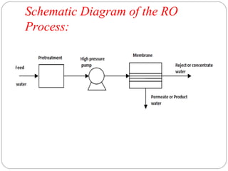
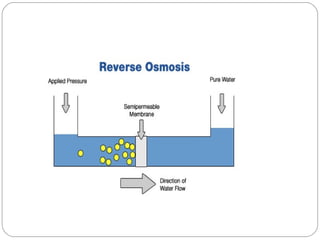
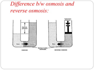
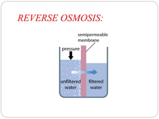
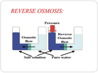
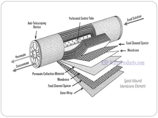
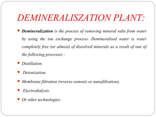
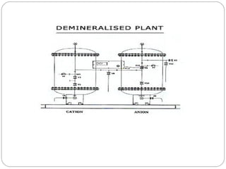
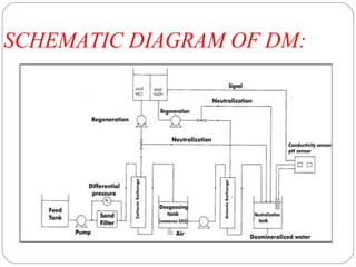
WATER TREATMENT BY REVERSE 
OSMOSIS AND DEMINERALISATION 
PLANT 
MALLA REDDY COLLEGE OF PHARMACY 
PRESENTATION BY: 
VOSKULA RAJESH 
M.PHARM.CEUTICES 1YEAR 
ROLL NO:256212880033
Abstract: 
Reverse Osmosis (RO) is a membrane based process technology to 
purify water by separating the dissolved solids from feed stream 
resulting in permeate and reject stream for a wide range of applications 
in domestic as well as industrial applications. It is seen from literature 
review that RO technology is used to remove dissolved solids, colour, 
organic contaminants, and nitrate from feed stream. Hence RO 
technology used in the treatment of water and hazardous waste, 
separation processes in the food, beverage and paper industry, as well 
as recovery of organic and inorganic materials from chemical processes 
as an alternative method .
Introduction: 
 Reverse Osmosis (RO) is a process that uses semipermeable spiral 
wound membranes to separate and remove dissolved solids, organic, 
pyrogens,submicron colloidal matter, color, nitrate and bacteria from 
water. Feed water is delivered under pressure through the semi 
permeable membrane, where water permeates the minute pores of the 
membrane and is delivered as purified water called permeate water. 
Impurities in the water are concentrated in the reject stream and 
flushed to the drain is called reject water. These membranes are semi-permeable 
and reject the salt ions while letting the water molecules 
pass. The materials used for RO membranes are made of cellulose 
acetate, and other polymers.
Scope of Reverse Osmosis: 
The process has also been applied to treat municipal wastewater. Since 
conventional municipal treatment processes do not remove dissolved 
solids, but RO process is used for the removal of dissolved solids. RO is 
increasingly used as a separation technique in chemical and 
environmental engineering for the removal of organics and organic 
pollutants present in wastewater. It is seen from literature review that 
Reverse Osmosis (RO) processes have been widely used for separation 
and concentration (recovery) of solutes in many fields.
Treatment options for Reverse 
Osmosis: 
In India, distillery uses various forms of primary, 
secondary and tertiary treatments of wastewater. The units processes used are 
screening and equalization, followed by biomethanation. Fertiirrigation and 
biocomposting with sugarcane pressmud are the most widely used options for 
effluent disposal.In case of grain based distillery the treatment given is by way 
of DWGS separation, incineration and biomethanation. The process streams 
that can be recycled are namely, thin slop and process condensate.Thin slop 
contain high TDS, high temperature and contain carbohydrates, organic acids, 
dead yeast cells etc. which may have an impact on the fermentation process.
Reverse Osmosis Process 
Description: 
The RO process is simple in design consisting of feed,permeate and reject 
stream. For feed water it is necessary to provide pretreatment in order to remove 
inorganic solids and suspended solid and using high pressure pump given feed 
through semi permeable membrane. Depending upon the permeate where it is 
used necessary post treatment is given..
Schematic Diagram of the RO 
Process:
Difference b/w osmosis and 
reverse osmosis:
REVERSE OSMOSIS:
REVERSE OSMOSIS:
Reverse Osmosis Requisites: 
An RO desalination plant essentially consists of four major systems: 
(a) Pretreatment system, 
(b) Highpressure pumps, 
(c) Membrane systems, and 
(d) Post-treatment.
 Pre-treatment system is provided to remove all suspended solids so 
that salt precipitation or microbial growth does not occur on the 
membranes. 
 Pre-treatment may involve conventional methods like a chemical feed 
followed by coagulation/ flocculation/sedimentation, and sand 
filtration or membrane processes i.e micro filtration (MF) and ultra 
filtration (UF). 
 The pressure ranges from 17 to 27 bar for brackish water, and from 52 
to 69 bar for seawater. Membrane systems consist of a pressure vessel 
and a semi-permeable membrane inside that permits the feed water to 
pass through it.
Basic components common of a 
Reverse Osmosis System: 
 Cold Water Line Valve: Valve that fits onto the cold water supply line. 
The valve has a tube that attaches to the inlet side of the RO pre filter. 
 Pre-Filter (s): Water from the cold water supply line enters the Reverse 
Osmosis Pre Filter first. There may be more than one pre-filter used in 
a Reverse Osmosis system. The most commonly used pre-filters are 
sediment filters. These are used to remove sand silt, dirt and other 
sediment. 
 Additionally, carbon filters may be used to remove chlorine, which can 
have a negative effect on TFC (thin film composite) & TFM (thin film 
material) membranes.
 Flow Restrictor: Water flow through the RO membrane is regulated 
by a flow control. There are many different styles of flow controls. This 
device maintains the flow rate required to obtain the highest quality 
drinking water (based on the gallon capacity of the membrane). It also 
helps maintain pressure on the inlet side of the membrane. Without the 
flow control very little drinking water would be produced because all 
the incoming tap water would take the path of least resistance and 
simply flow down the drain line. The flow control is located in the RO 
drain line tubing. 
 Storage Tank: The standard RO storage tank holds up to 2.5 gallons 
of water. A bladder inside the tank keeps water pressurized in the tank 
when it is full. 
 Faucet: The RO unit uses its own faucet in areas where required by 
plumbing codes an air-gap faucet is generally used. 
 Drain line: This line runs from the outlet end of the Reverse Osmosis 
membrane housing to the drain. This line is used to dispose of the 
impurities and contaminants found in the incoming water source (tap 
water). The flow control is also installed in this line.
Membrane Characteristics: 
 The membrane should be inexpensive, have longer and stable life. 
 Membrane should be easily manufactured with good salt rejection i.e. 
Slightly permeable to salt. 
 They should have high water flux i.e highly permeable to water and 
less susceptible to fouling. 
 They should permit the flow of large amounts of water through the 
membrane relative to the volume they occupy. 
 The membrane should chemically, physically and thermally stable in 
saline waters. 
 They need to be strong enough to withstand high pressures and 
variable feed water quality
TYPES OF MEMBRANES:
Advantages of RO Process: 
Following are the advantages of the RO process that make it attractive 
for dilute aqueous wastewater treatment include: 
 RO systems are simple to design and operate, have low maintenance 
requirements, and are modular in nature, making expansion of the 
systems easy. 
 Both inorganic and organic pollutants can be removed simultaneously 
by RO membrane processes. 
 RO systems allow recovery/recycle of waste process streams with no 
effect on the material being recovered. 
 RO systems require less energy as compared to other technology.
Advantages of reverse osmosis: 
 The modular structure of the RO proces increases flexibility in building 
desalination plants within a wide range of capacities. 
 The specific energy requirement is significantly low 3- 9.4 kW h/m3 product. 
The process is electrically driven hence it is readily adaptable to powering by 
solar panels. 
Treatment (as well as many others) to produce high quality product water that can 
be reused or discharged.
Applications of Reverse Osmosis: 
This technology has advantage of a 
membrane based process where concentration and separation is 
achieved without a change of state and without use of chemicals or 
thermal energy, thus making the process energy efficient and ideally 
suited for recovery applications. The bibliographic review shows 
applicability of RO system for treating effluents from beverage 
industry, distillery spent wash, ground water treatment, recovery of 
phenol compounds, and reclamation of wastewater and sea water 
reverse osmosis (SWRO) treatment indicating efficiency and 
applicability of RO technology.
Marketed systems of reverse 
osmosis: 
1)Culligan Reverse Osmosis Products 
G3 / G3+ Reverse Osmosis System: 
2)G2 Reverse Osmosis System 
This flexible system is sized to provide high-quality reverse 
osmosis water for large applications from 18 to over 200* gallons per 
minute. The G3 can be a fully integrated part of your Culligan Matrix 
Solution.
MARKETED REVERSE OSMOSIS 
MACHINES: 
• M2 Reverse Osmosis System 
• E2 Reverse Osmosis System
MARKETED REVERSE OSMOSIS 
MACHINES: 
G1 Reverse Osmosis System 
M1 Reverse Osmosis System
DEMINERALISZATION PLANT: 
 Demineralization is the process of removing mineral salts from water 
by using the ion exchange process. Demineralised water is water 
completely free (or almost) of dissolved minerals as a result of one of 
the following processes : 
 Distillation. 
 Deionization. 
 Membrane filtration (reverse osmosis or nanofiltration). 
 Electrodialysis. 
 Or other technologies.
Principle : 
Raw water is passed via two small polystyrene bead 
filled (ion exchange resins) beds. 
While the cations get exchanged with hydrogen ions in 
first bed. 
The anions are exchanged with hydroxyl ions, in the 
second one.
Process : 
In the context of water purification, ion-exchange is a rapid and 
reversible process in which impurity ions present in the water 
are replaced by ions released by an ion-exchange resin. 
The impurity ions are taken up by the resin, which must be 
periodically regenerated to restore it to the original ionic form. 
An ion is an atom or group of atoms with an electric charge. 
Positively-charged ions are called cations and are usually 
metals; negatively-charged ions are called anions and are 
usually non-metals.
SCHEMATIC DIAGRAM OF DM:
The following ions are widely 
found in raw waters : 
Cations: 
Calcium (Ca2+) 
Magnesium (Mg2+) 
Sodium (Na+) 
Potassium (K+) 
Anions: 
Chloride ( Cl-) 
Bicarbonate (HCO3-) 
Nitrate (NO3-) 
Carbonate (CO32-)
DM TANKS:
DM PLANT. CAPACITY: 2 X 15 
M3/HR:
Ion Exchange Resins : 
There are two basic types of resin – 
1)Cation-exchange resins. 
2) Anion-exchange resins. 
Cation exchange resins will release Hydrogen (H+) ions or 
other positively charged ions in exchange for impurity cations present 
in the water. Anion exchange resins will release hydroxyl (OH-) ions or 
other negatively charged ions in exchange for impurity anions present 
in the water.
The application of ion-exchange 
to water treatment and 
purification 
There are three ways in which ion-exchange technology can be used in 
water treatment and purification : 
 First, cation-exchange resins alone can be employed to soften water by 
base exchange. 
 Secondly, anion-exchange resins alone can be used for organic 
scavenging or nitrate removal. 
 Thirdly, combinations of cation-exchange and anion-exchange resins 
can be used to remove virtually all the ionic impurities present in the 
feedwater, a process known as deionization. Water deionizers 
purification process results in water of exceptionally high quality.
Deionization : 
For many laboratory and industrial applications, high-purity 
water which is essentially free from ionic contaminants is required. 
Water of this quality can be produced by deionization. The two most 
common types of deionization are : 
 Two-bed deionization. 
 Mixed-bed deionization.
Two-bed deionization : 
The two-bed deionizer consists of two vessels - one 
containing a cation-exchange resin in the hydrogen (H+) form and the 
other containing an anion resin in the hydroxyl (OH-) form. Water 
flows through the cation column, whereupon all the cations are 
exchanged for hydrogen ions. To keep the water electrically balanced, 
for every monovalent cation. 
e.g: Ca2+, or Mg2+, two hydrogen ions are exchanged. The 
same principle applies when considering anion-exchange. The 
decationised water then flows through the anion column. This time, all 
the negatively charged ions are exchanged for hydroxide ions which 
then combine with the hydrogen ions to form water (H2O).
DM PLANT:
MIXED-BED DEIONIZER: 
 In mixed-bed deionizers the cation-exchange and anion-exchange 
resins are intimately mixed and contained in a single pressure vessel. 
The thorough mixture of cation-exchangers and anion-exchangers in a 
single column makes a mixed-bed deionizer equivalent to a lengthy 
series of two-bed plants. As a result, the water quality obtained from a 
mixed-bed deionizer is appreciably higher than that produced by a 
two-bed plant.
Mixed-bed deionization:
Mini DM Plant Specifications : 
Model: eDM-5 
Flow rate: 50 to 80 Lit/hr. 
Space requirement: very compact- 1 m x 1m 
Power: NIL, Min inlet pressure 0.5 kg/cm2 
Output TDS: Less that 10 ppm 
Output DM Qty.: 500 Lit at 100 ppm TDS 
(Best suitable when feed water is corporation water TDS < 100 ppm)
Advantages : 
 Variety of cost effective standard models. 
 Improved aesthetics and rugged design. 
 User friendly, low maintenance and easy to install. 
 Simpler distribution and collection systems. 
 Quick availability. 
 Pre dispatch assembly check. 
 The multiport valves are top mounted as well as side mounted with 
the necessary high pressure rating PVC piping. 
 Single valve operation as compared to the six valves in conventional 
filters.
Advantages : 
 Each operating step is clearly marked on the valve, thereby eliminating 
chances of error in the operating sequence. 
 Single valve assembly, with its simplified frontal Piping, simpler 
distribution collecting systems is Very easy to install. 
 Rust free. 
 Less power consumption. 
 Durable. 
 Economical. 
 High shelf life.
APPLICATIONS: 
 Boilers feed water, Textiles, Pharmaceuticals, Chemicals, Breweries, 
Swimming pools, Potable Water, Hospitals, Automobile, and 
Battery, Fertilizers. 
 Ion Exchange Plants 
- Softener. 
- Industrial DM Plant. 
- Two Stage & Multi Stage DM Plants. 
- Mix Bed Demineraliser. 
- De-Gasifiers. 
- Cation Polisher. 
- Manual/Automatic Plants. 
- Pharmaceutical Industry. 
- Power Plant. 
- Oil & Gas sector. 
- Chemical Industries. 
- Textile Industries.
Conclusion: 
Feed Water containing suspended particles, 
organic matter as well as inorganic salt may deposit on the membrane 
and fouling will occur or damage the membrane because of applied 
pressure and size of particles. Therefore the priority to remove these by 
way of pretreatment will determine the RO efficiency. Hence RO 
membrane performance can be checked to avoid the irreversible 
damages to the RO membrane. In fact success of RO system depends 
upon efficiency of the pre treatment.
References: 
 *Garud R. M., Kore S. V., Kore V. S., Kulkarni G. S. A Short Review 
on Process and Applications of Reverse Osmosis from universal 
journal of environamental research and technology. Volume 1;issue 
3:233-238. 
 Bellona, C., J.E. Drewes, P. Xua and G.Amy,(2004):,”Factors 
affecting the rejection of organic solutes during NF/RO treatment-a 
literature review, “Water Res., 38: 2795-2809. 
 Bodalo-Santoyo, A., J.L. Gomez-Carrasco, E. Gomez-Gomez, 
F.Maximo -Martin and A.M. Hidalgo-Montesinos,(2003):,”Application 
of reverse osmosis membrane to reduce pollutants present in industrial 
waste water , “Desalination155: 101-108.
 Chian, E., Bruce, W., and Fang, H., (1975):"Removal of Pesticides by 
Reverse Osmosis",Environmental Science and Technology, 9- 364. 
 Craig J. Brown P.Eng Presented by: Phillip J. Simmons PhD, Eco-Tec 
Inc., , Ontario, Canada Presented at the Water Management in 
Process Industry, organized by the Lovraj Kumar Memorial Trust, 
India, November, 2002. 
 Smith, J.H., Renouf, P.W., Crossen, M., “50 Years in Separate Beds”, 
Proceedings of the International Water Conference 1984. 
 Craig J. Brown P.Eng Presented by: Phillip J. Simmons PhD, Eco-Tec 
Inc., , Ontario, Canada Presented at the Water Management in 
Process Industry, organized by the Lovraj Kumar Memorial Trust, 
India, November, 2002.
I HOPE YOU 
UNDERTSOOD 
SOMETHING….. 
…..THANQ U

Water treatment by demineralisation

  • 1.
    WATER TREATMENT BYREVERSE OSMOSIS AND DEMINERALISATION PLANT MALLA REDDY COLLEGE OF PHARMACY PRESENTATION BY: VOSKULA RAJESH M.PHARM.CEUTICES 1YEAR ROLL NO:256212880033
  • 2.
    Abstract: Reverse Osmosis(RO) is a membrane based process technology to purify water by separating the dissolved solids from feed stream resulting in permeate and reject stream for a wide range of applications in domestic as well as industrial applications. It is seen from literature review that RO technology is used to remove dissolved solids, colour, organic contaminants, and nitrate from feed stream. Hence RO technology used in the treatment of water and hazardous waste, separation processes in the food, beverage and paper industry, as well as recovery of organic and inorganic materials from chemical processes as an alternative method .
  • 3.
    Introduction:  ReverseOsmosis (RO) is a process that uses semipermeable spiral wound membranes to separate and remove dissolved solids, organic, pyrogens,submicron colloidal matter, color, nitrate and bacteria from water. Feed water is delivered under pressure through the semi permeable membrane, where water permeates the minute pores of the membrane and is delivered as purified water called permeate water. Impurities in the water are concentrated in the reject stream and flushed to the drain is called reject water. These membranes are semi-permeable and reject the salt ions while letting the water molecules pass. The materials used for RO membranes are made of cellulose acetate, and other polymers.
  • 4.
    Scope of ReverseOsmosis: The process has also been applied to treat municipal wastewater. Since conventional municipal treatment processes do not remove dissolved solids, but RO process is used for the removal of dissolved solids. RO is increasingly used as a separation technique in chemical and environmental engineering for the removal of organics and organic pollutants present in wastewater. It is seen from literature review that Reverse Osmosis (RO) processes have been widely used for separation and concentration (recovery) of solutes in many fields.
  • 5.
    Treatment options forReverse Osmosis: In India, distillery uses various forms of primary, secondary and tertiary treatments of wastewater. The units processes used are screening and equalization, followed by biomethanation. Fertiirrigation and biocomposting with sugarcane pressmud are the most widely used options for effluent disposal.In case of grain based distillery the treatment given is by way of DWGS separation, incineration and biomethanation. The process streams that can be recycled are namely, thin slop and process condensate.Thin slop contain high TDS, high temperature and contain carbohydrates, organic acids, dead yeast cells etc. which may have an impact on the fermentation process.
  • 6.
    Reverse Osmosis Process Description: The RO process is simple in design consisting of feed,permeate and reject stream. For feed water it is necessary to provide pretreatment in order to remove inorganic solids and suspended solid and using high pressure pump given feed through semi permeable membrane. Depending upon the permeate where it is used necessary post treatment is given..
  • 7.
    Schematic Diagram ofthe RO Process:
  • 9.
    Difference b/w osmosisand reverse osmosis:
  • 10.
  • 11.
  • 13.
    Reverse Osmosis Requisites: An RO desalination plant essentially consists of four major systems: (a) Pretreatment system, (b) Highpressure pumps, (c) Membrane systems, and (d) Post-treatment.
  • 14.
     Pre-treatment systemis provided to remove all suspended solids so that salt precipitation or microbial growth does not occur on the membranes.  Pre-treatment may involve conventional methods like a chemical feed followed by coagulation/ flocculation/sedimentation, and sand filtration or membrane processes i.e micro filtration (MF) and ultra filtration (UF).  The pressure ranges from 17 to 27 bar for brackish water, and from 52 to 69 bar for seawater. Membrane systems consist of a pressure vessel and a semi-permeable membrane inside that permits the feed water to pass through it.
  • 15.
    Basic components commonof a Reverse Osmosis System:  Cold Water Line Valve: Valve that fits onto the cold water supply line. The valve has a tube that attaches to the inlet side of the RO pre filter.  Pre-Filter (s): Water from the cold water supply line enters the Reverse Osmosis Pre Filter first. There may be more than one pre-filter used in a Reverse Osmosis system. The most commonly used pre-filters are sediment filters. These are used to remove sand silt, dirt and other sediment.  Additionally, carbon filters may be used to remove chlorine, which can have a negative effect on TFC (thin film composite) & TFM (thin film material) membranes.
  • 16.
     Flow Restrictor:Water flow through the RO membrane is regulated by a flow control. There are many different styles of flow controls. This device maintains the flow rate required to obtain the highest quality drinking water (based on the gallon capacity of the membrane). It also helps maintain pressure on the inlet side of the membrane. Without the flow control very little drinking water would be produced because all the incoming tap water would take the path of least resistance and simply flow down the drain line. The flow control is located in the RO drain line tubing.  Storage Tank: The standard RO storage tank holds up to 2.5 gallons of water. A bladder inside the tank keeps water pressurized in the tank when it is full.  Faucet: The RO unit uses its own faucet in areas where required by plumbing codes an air-gap faucet is generally used.  Drain line: This line runs from the outlet end of the Reverse Osmosis membrane housing to the drain. This line is used to dispose of the impurities and contaminants found in the incoming water source (tap water). The flow control is also installed in this line.
  • 18.
    Membrane Characteristics: The membrane should be inexpensive, have longer and stable life.  Membrane should be easily manufactured with good salt rejection i.e. Slightly permeable to salt.  They should have high water flux i.e highly permeable to water and less susceptible to fouling.  They should permit the flow of large amounts of water through the membrane relative to the volume they occupy.  The membrane should chemically, physically and thermally stable in saline waters.  They need to be strong enough to withstand high pressures and variable feed water quality
  • 19.
  • 20.
    Advantages of ROProcess: Following are the advantages of the RO process that make it attractive for dilute aqueous wastewater treatment include:  RO systems are simple to design and operate, have low maintenance requirements, and are modular in nature, making expansion of the systems easy.  Both inorganic and organic pollutants can be removed simultaneously by RO membrane processes.  RO systems allow recovery/recycle of waste process streams with no effect on the material being recovered.  RO systems require less energy as compared to other technology.
  • 21.
    Advantages of reverseosmosis:  The modular structure of the RO proces increases flexibility in building desalination plants within a wide range of capacities.  The specific energy requirement is significantly low 3- 9.4 kW h/m3 product. The process is electrically driven hence it is readily adaptable to powering by solar panels. Treatment (as well as many others) to produce high quality product water that can be reused or discharged.
  • 22.
    Applications of ReverseOsmosis: This technology has advantage of a membrane based process where concentration and separation is achieved without a change of state and without use of chemicals or thermal energy, thus making the process energy efficient and ideally suited for recovery applications. The bibliographic review shows applicability of RO system for treating effluents from beverage industry, distillery spent wash, ground water treatment, recovery of phenol compounds, and reclamation of wastewater and sea water reverse osmosis (SWRO) treatment indicating efficiency and applicability of RO technology.
  • 23.
    Marketed systems ofreverse osmosis: 1)Culligan Reverse Osmosis Products G3 / G3+ Reverse Osmosis System: 2)G2 Reverse Osmosis System This flexible system is sized to provide high-quality reverse osmosis water for large applications from 18 to over 200* gallons per minute. The G3 can be a fully integrated part of your Culligan Matrix Solution.
  • 24.
    MARKETED REVERSE OSMOSIS MACHINES: • M2 Reverse Osmosis System • E2 Reverse Osmosis System
  • 25.
    MARKETED REVERSE OSMOSIS MACHINES: G1 Reverse Osmosis System M1 Reverse Osmosis System
  • 26.
    DEMINERALISZATION PLANT: Demineralization is the process of removing mineral salts from water by using the ion exchange process. Demineralised water is water completely free (or almost) of dissolved minerals as a result of one of the following processes :  Distillation.  Deionization.  Membrane filtration (reverse osmosis or nanofiltration).  Electrodialysis.  Or other technologies.
  • 28.
    Principle : Rawwater is passed via two small polystyrene bead filled (ion exchange resins) beds. While the cations get exchanged with hydrogen ions in first bed. The anions are exchanged with hydroxyl ions, in the second one.
  • 29.
    Process : Inthe context of water purification, ion-exchange is a rapid and reversible process in which impurity ions present in the water are replaced by ions released by an ion-exchange resin. The impurity ions are taken up by the resin, which must be periodically regenerated to restore it to the original ionic form. An ion is an atom or group of atoms with an electric charge. Positively-charged ions are called cations and are usually metals; negatively-charged ions are called anions and are usually non-metals.
  • 30.
  • 31.
    The following ionsare widely found in raw waters : Cations: Calcium (Ca2+) Magnesium (Mg2+) Sodium (Na+) Potassium (K+) Anions: Chloride ( Cl-) Bicarbonate (HCO3-) Nitrate (NO3-) Carbonate (CO32-)
  • 32.
  • 33.
    DM PLANT. CAPACITY:2 X 15 M3/HR:
  • 34.
    Ion Exchange Resins: There are two basic types of resin – 1)Cation-exchange resins. 2) Anion-exchange resins. Cation exchange resins will release Hydrogen (H+) ions or other positively charged ions in exchange for impurity cations present in the water. Anion exchange resins will release hydroxyl (OH-) ions or other negatively charged ions in exchange for impurity anions present in the water.
  • 35.
    The application ofion-exchange to water treatment and purification There are three ways in which ion-exchange technology can be used in water treatment and purification :  First, cation-exchange resins alone can be employed to soften water by base exchange.  Secondly, anion-exchange resins alone can be used for organic scavenging or nitrate removal.  Thirdly, combinations of cation-exchange and anion-exchange resins can be used to remove virtually all the ionic impurities present in the feedwater, a process known as deionization. Water deionizers purification process results in water of exceptionally high quality.
  • 36.
    Deionization : Formany laboratory and industrial applications, high-purity water which is essentially free from ionic contaminants is required. Water of this quality can be produced by deionization. The two most common types of deionization are :  Two-bed deionization.  Mixed-bed deionization.
  • 37.
    Two-bed deionization : The two-bed deionizer consists of two vessels - one containing a cation-exchange resin in the hydrogen (H+) form and the other containing an anion resin in the hydroxyl (OH-) form. Water flows through the cation column, whereupon all the cations are exchanged for hydrogen ions. To keep the water electrically balanced, for every monovalent cation. e.g: Ca2+, or Mg2+, two hydrogen ions are exchanged. The same principle applies when considering anion-exchange. The decationised water then flows through the anion column. This time, all the negatively charged ions are exchanged for hydroxide ions which then combine with the hydrogen ions to form water (H2O).
  • 38.
  • 39.
    MIXED-BED DEIONIZER: In mixed-bed deionizers the cation-exchange and anion-exchange resins are intimately mixed and contained in a single pressure vessel. The thorough mixture of cation-exchangers and anion-exchangers in a single column makes a mixed-bed deionizer equivalent to a lengthy series of two-bed plants. As a result, the water quality obtained from a mixed-bed deionizer is appreciably higher than that produced by a two-bed plant.
  • 40.
  • 41.
    Mini DM PlantSpecifications : Model: eDM-5 Flow rate: 50 to 80 Lit/hr. Space requirement: very compact- 1 m x 1m Power: NIL, Min inlet pressure 0.5 kg/cm2 Output TDS: Less that 10 ppm Output DM Qty.: 500 Lit at 100 ppm TDS (Best suitable when feed water is corporation water TDS < 100 ppm)
  • 42.
    Advantages : Variety of cost effective standard models.  Improved aesthetics and rugged design.  User friendly, low maintenance and easy to install.  Simpler distribution and collection systems.  Quick availability.  Pre dispatch assembly check.  The multiport valves are top mounted as well as side mounted with the necessary high pressure rating PVC piping.  Single valve operation as compared to the six valves in conventional filters.
  • 43.
    Advantages : Each operating step is clearly marked on the valve, thereby eliminating chances of error in the operating sequence.  Single valve assembly, with its simplified frontal Piping, simpler distribution collecting systems is Very easy to install.  Rust free.  Less power consumption.  Durable.  Economical.  High shelf life.
  • 44.
    APPLICATIONS:  Boilersfeed water, Textiles, Pharmaceuticals, Chemicals, Breweries, Swimming pools, Potable Water, Hospitals, Automobile, and Battery, Fertilizers.  Ion Exchange Plants - Softener. - Industrial DM Plant. - Two Stage & Multi Stage DM Plants. - Mix Bed Demineraliser. - De-Gasifiers. - Cation Polisher. - Manual/Automatic Plants. - Pharmaceutical Industry. - Power Plant. - Oil & Gas sector. - Chemical Industries. - Textile Industries.
  • 45.
    Conclusion: Feed Watercontaining suspended particles, organic matter as well as inorganic salt may deposit on the membrane and fouling will occur or damage the membrane because of applied pressure and size of particles. Therefore the priority to remove these by way of pretreatment will determine the RO efficiency. Hence RO membrane performance can be checked to avoid the irreversible damages to the RO membrane. In fact success of RO system depends upon efficiency of the pre treatment.
  • 46.
    References:  *GarudR. M., Kore S. V., Kore V. S., Kulkarni G. S. A Short Review on Process and Applications of Reverse Osmosis from universal journal of environamental research and technology. Volume 1;issue 3:233-238.  Bellona, C., J.E. Drewes, P. Xua and G.Amy,(2004):,”Factors affecting the rejection of organic solutes during NF/RO treatment-a literature review, “Water Res., 38: 2795-2809.  Bodalo-Santoyo, A., J.L. Gomez-Carrasco, E. Gomez-Gomez, F.Maximo -Martin and A.M. Hidalgo-Montesinos,(2003):,”Application of reverse osmosis membrane to reduce pollutants present in industrial waste water , “Desalination155: 101-108.
  • 47.
     Chian, E.,Bruce, W., and Fang, H., (1975):"Removal of Pesticides by Reverse Osmosis",Environmental Science and Technology, 9- 364.  Craig J. Brown P.Eng Presented by: Phillip J. Simmons PhD, Eco-Tec Inc., , Ontario, Canada Presented at the Water Management in Process Industry, organized by the Lovraj Kumar Memorial Trust, India, November, 2002.  Smith, J.H., Renouf, P.W., Crossen, M., “50 Years in Separate Beds”, Proceedings of the International Water Conference 1984.  Craig J. Brown P.Eng Presented by: Phillip J. Simmons PhD, Eco-Tec Inc., , Ontario, Canada Presented at the Water Management in Process Industry, organized by the Lovraj Kumar Memorial Trust, India, November, 2002.
  • 48.
    I HOPE YOU UNDERTSOOD SOMETHING….. …..THANQ U