
Download as PDF, PPTX
![UK Power System
Electricity Supplied by Fuel Type in 2010:
Transmission System Operators (TSOs):
• National Grid
• Scottish and Southern Energy
• Scottish Power
System Data:
Circuit Voltage Circuit Length
TSO
[kV] [km]
National Grid 400, 275 ~14,000
Scottish and
275, 132 ~5,000
Southern Energy
Scottish Power 400, 275, 132 ~4,000
THE UNIVERSITY
of BIRMINGHAM](https://image.slidesharecdn.com/wang-130324234524-phpapp01/75/Wang-Workshop-on-Modelling-and-Simulation-of-Coal-fired-Power-Generation-and-CCS-Process-12-2048.jpg)
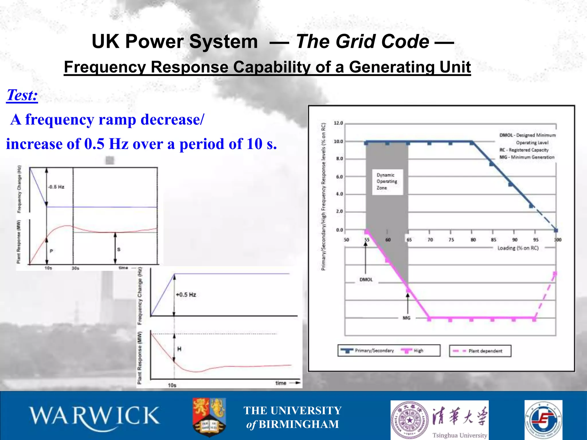
![UK Power System — The Grid Code —
Nominal Frequency: 50 Hz
Frequency Variation Interval [Hz]
Normal
Critical Situations
Operation
49.5 – 50.5 47.0 – 52.0
Frequency Control Strategies
Type of Frequency Control
Response Time
Strategy
active power increase within 10 s and
Primary Frequency Response
maintained for another 30 s
active power increase within 30 s and
Secondary Frequency Response
maintained for another 30 min
active power decrease within 10 s and
High Frequency Response
maintained thereafter
THE UNIVERSITY
of BIRMINGHAM](https://image.slidesharecdn.com/wang-130324234524-phpapp01/75/Wang-Workshop-on-Modelling-and-Simulation-of-Coal-fired-Power-Generation-and-CCS-Process-13-2048.jpg)
![Power Plant Modelling
Model Parameters identification process in Matlab®/Simulink®
Model = structure + parameters
Integrating the intelligent optimisation algorithms with the power plant
model for parameters identification
Plant measurement
DATA from
SC Power Plant
Data input to model
Simulated and
MATLAB® Parameters SIMULINK®
measured
Genetic update Simulation Stopping YES
outputs Model
Algorithm for new criterion
parameters
Parameters
[Toolbox] met
(+measurement ?
input DATA)
NO](https://image.slidesharecdn.com/wang-130324234524-phpapp01/75/Wang-Workshop-on-Modelling-and-Simulation-of-Coal-fired-Power-Generation-and-CCS-Process-22-2048.jpg)
![Power Plant Modelling
Model Parameters Verification – Results for the best parameters set
0.9
0.8
PM [pu]
0.7 Pm – mechanical power
000
0.6
0.5
0.4
0.3
2000 4000 6000 8000 10000 12000 14000
t [s]
1
0.9
MSP [pu]
0.8
0.7 00
MSP – main steam pressure
0.6
0.5
0.4
2000 4000 6000 8000 10000 12000 14000
t [s]
0.8
RHP [pu]
0.7
00
RHP – reheater pressure
0.6
0.5
0.4
data from industry
0.3
2000 4000 6000 8000 10000 12000 14000 Simulink model
t [s]](https://image.slidesharecdn.com/wang-130324234524-phpapp01/75/Wang-Workshop-on-Modelling-and-Simulation-of-Coal-fired-Power-Generation-and-CCS-Process-24-2048.jpg)

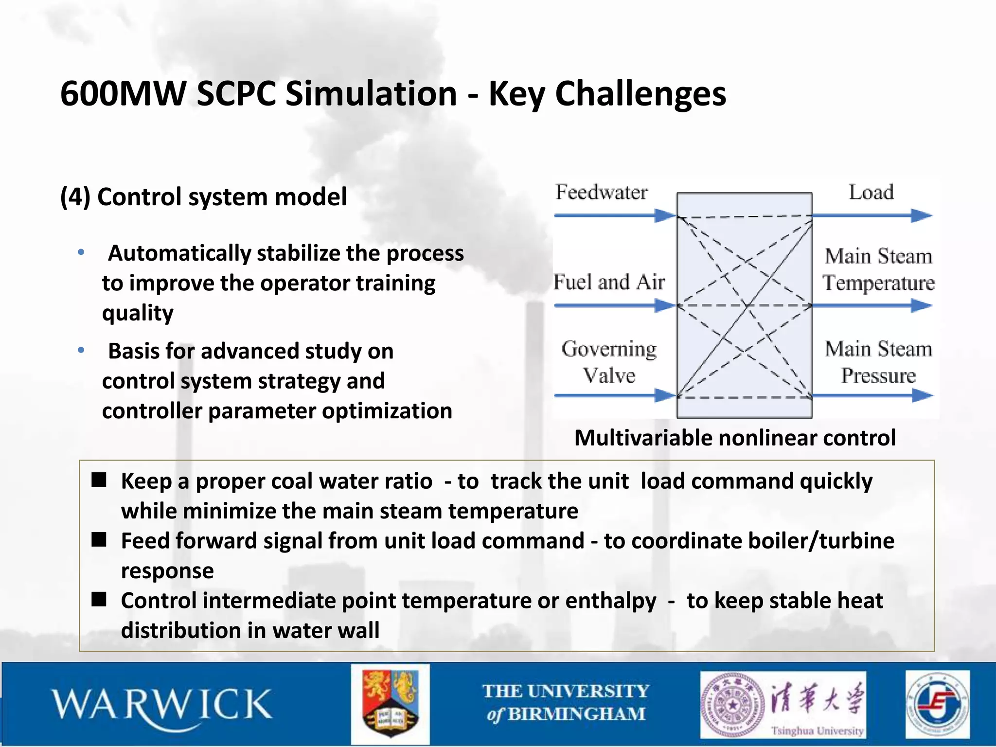
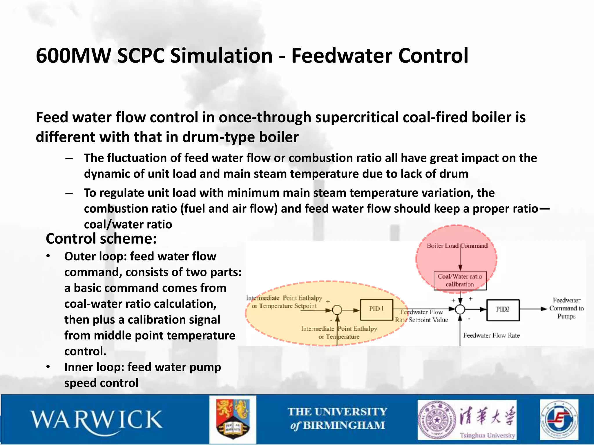
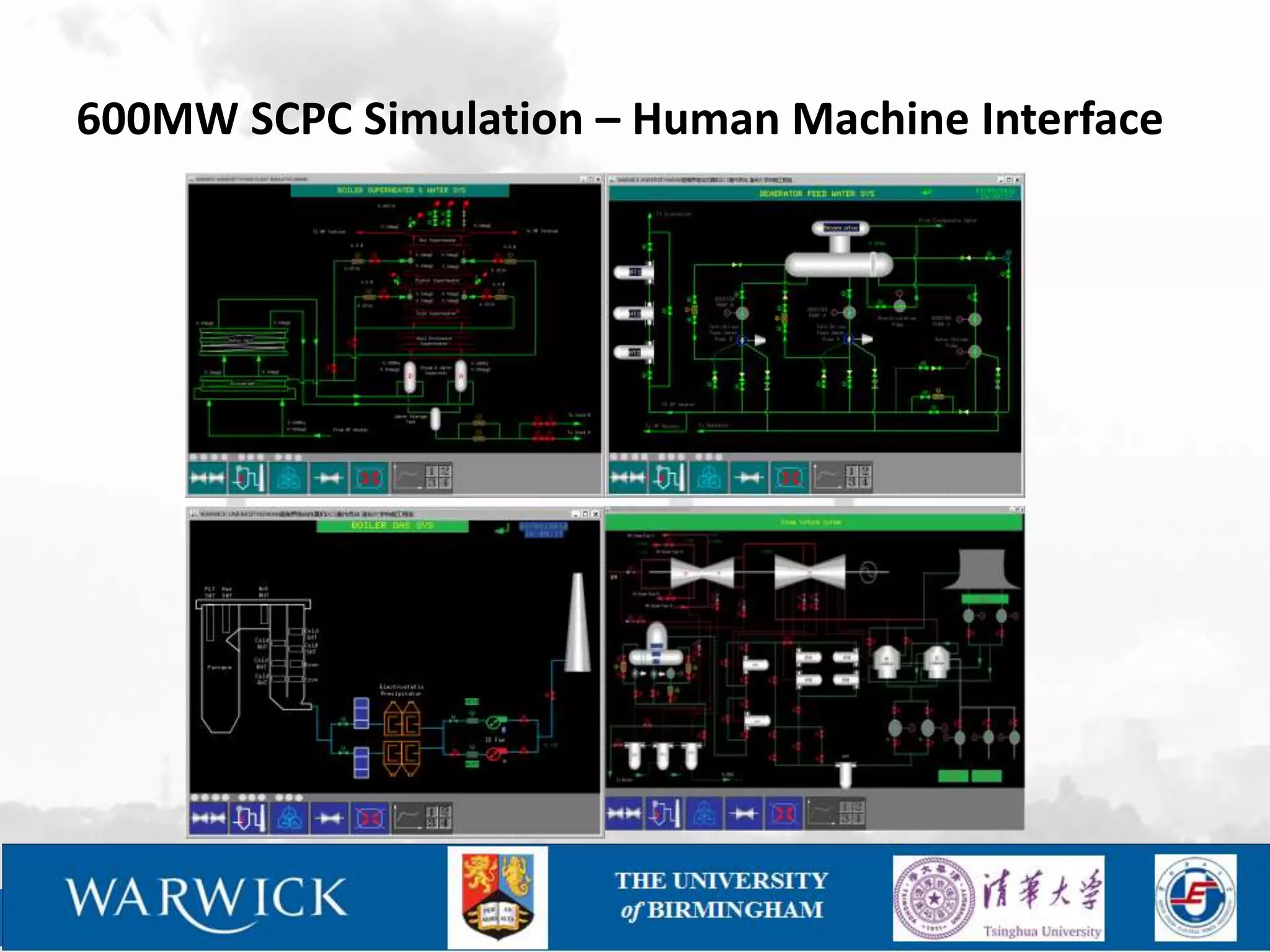
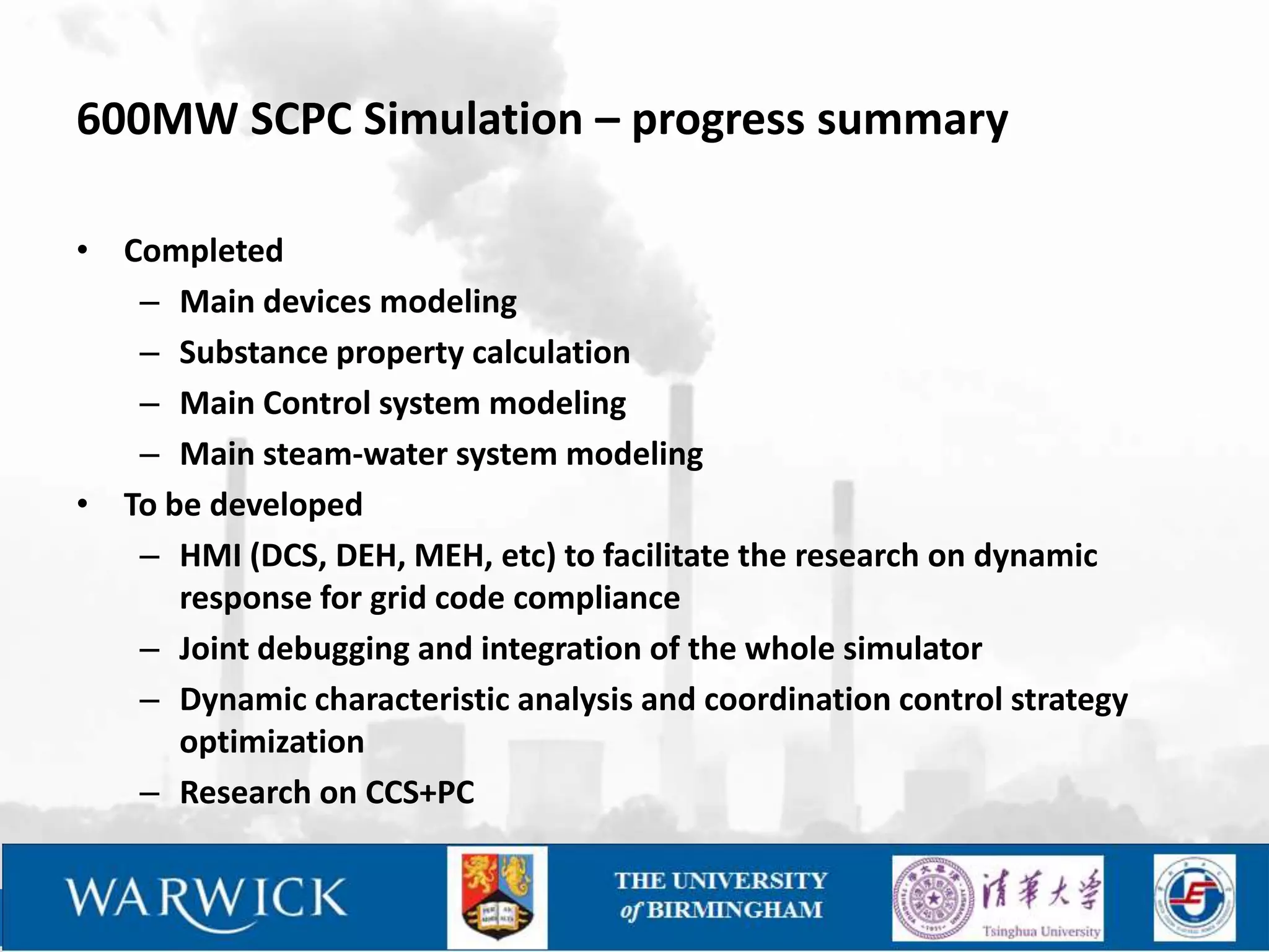
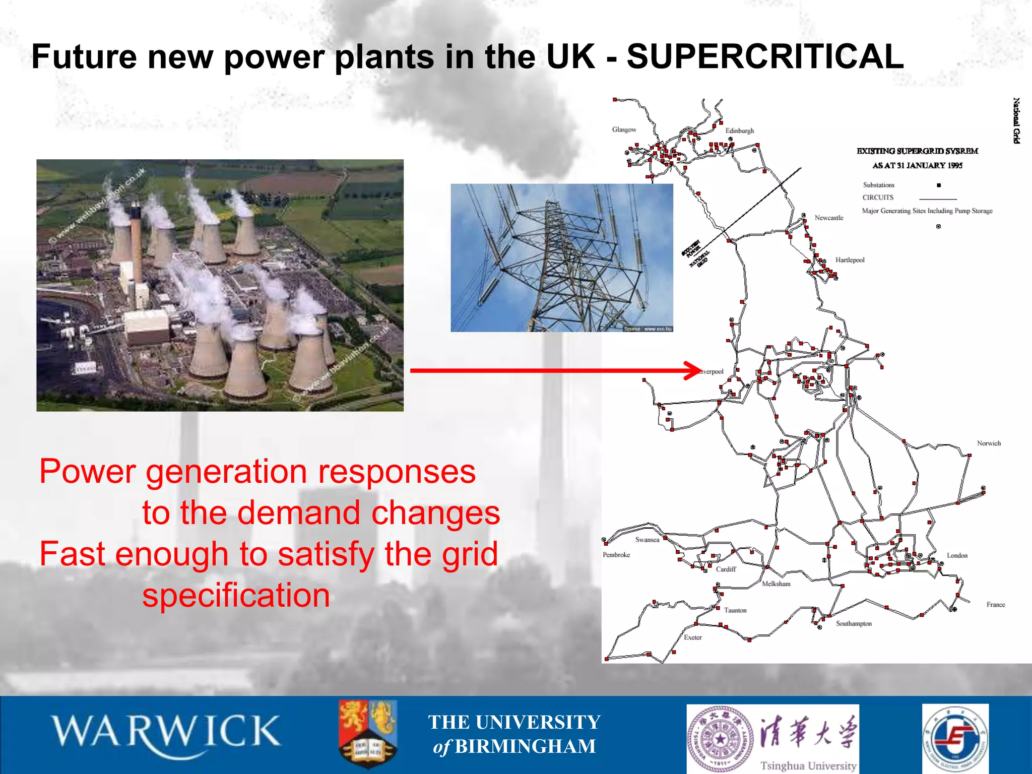
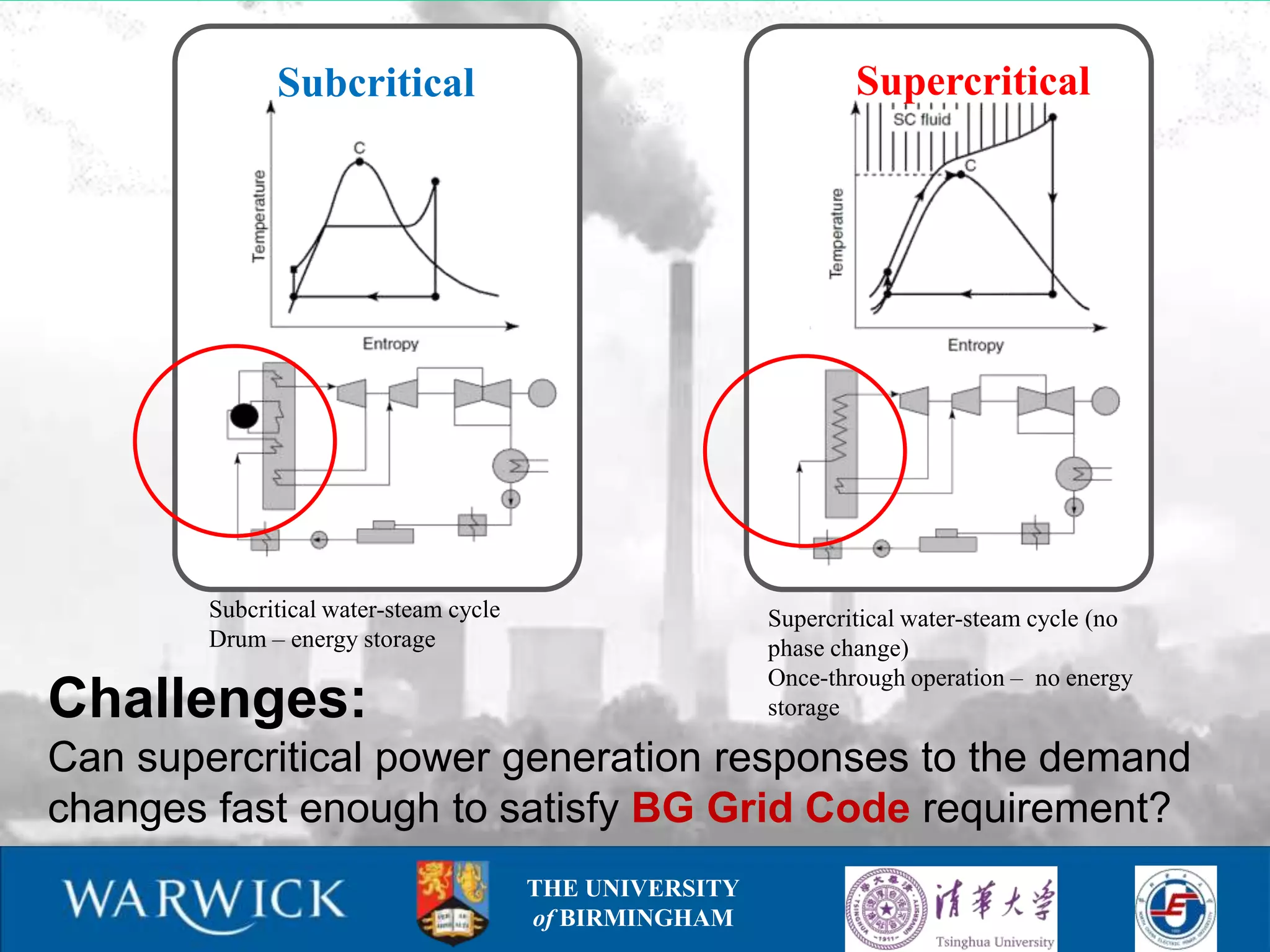
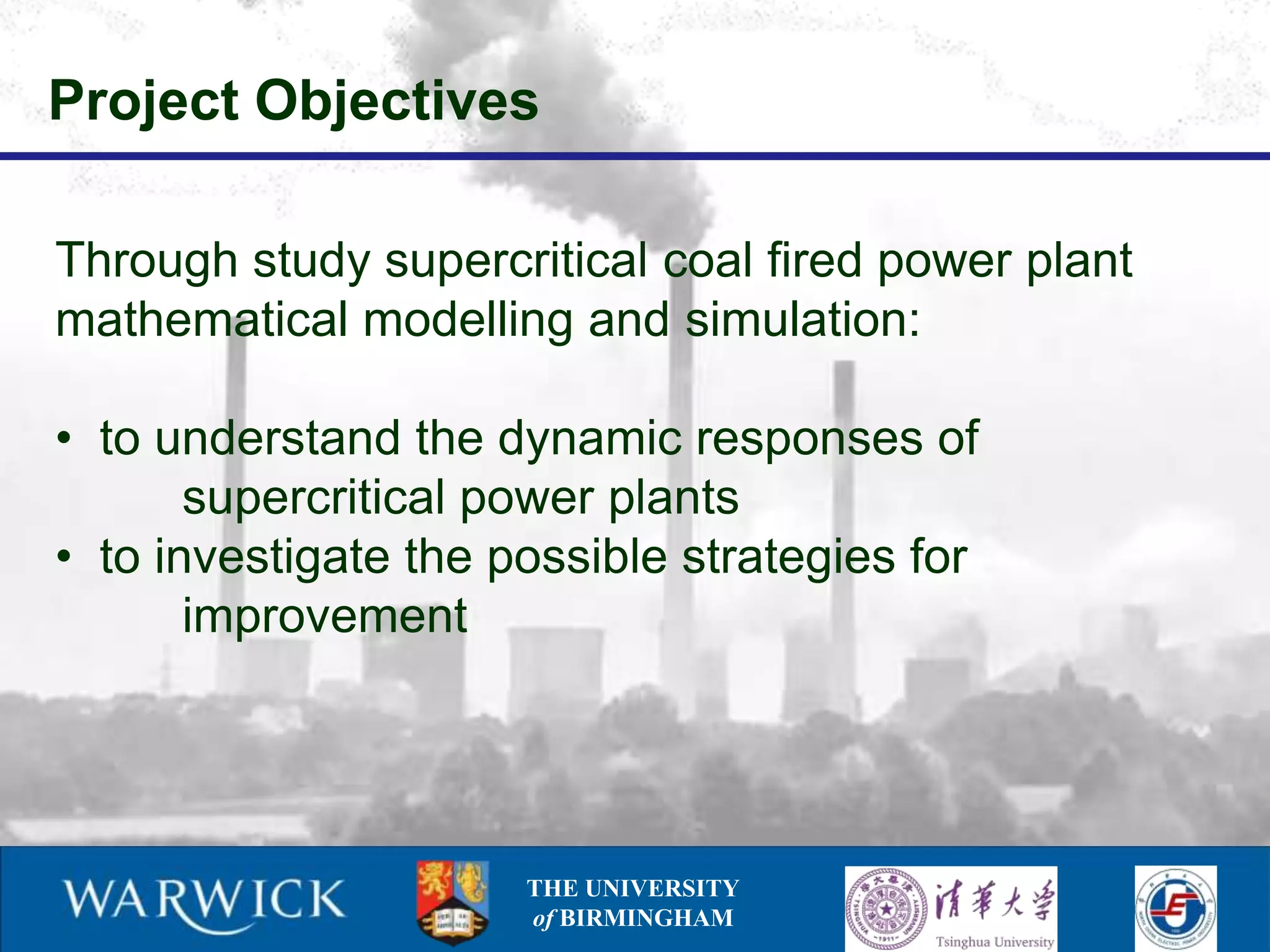
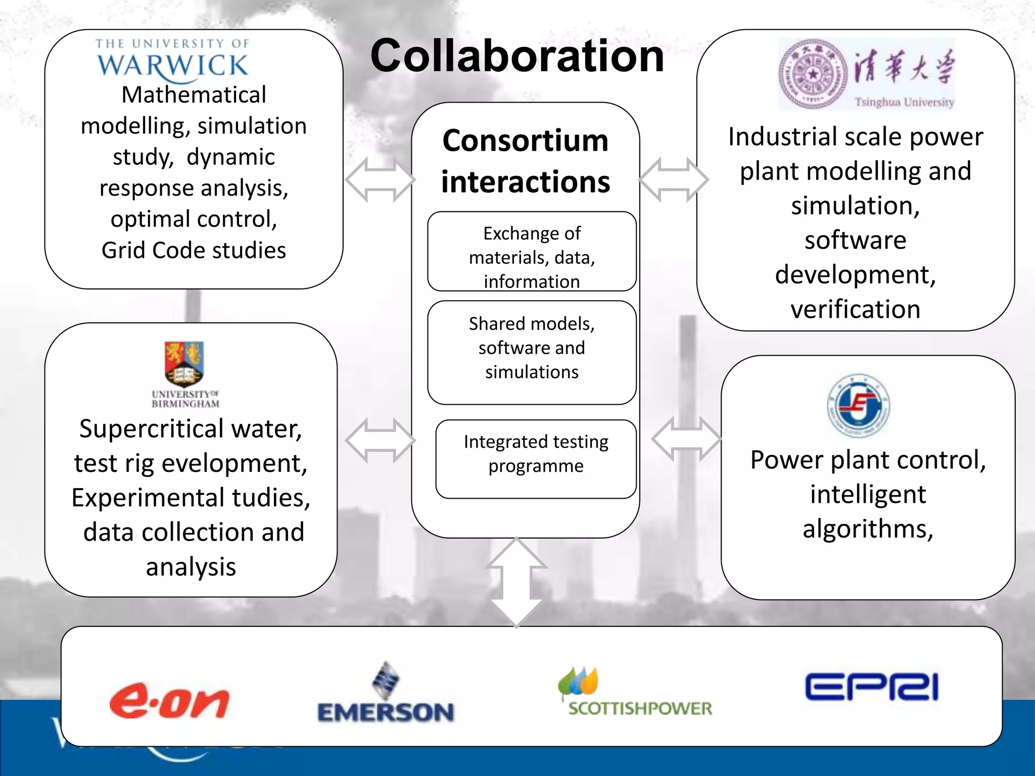
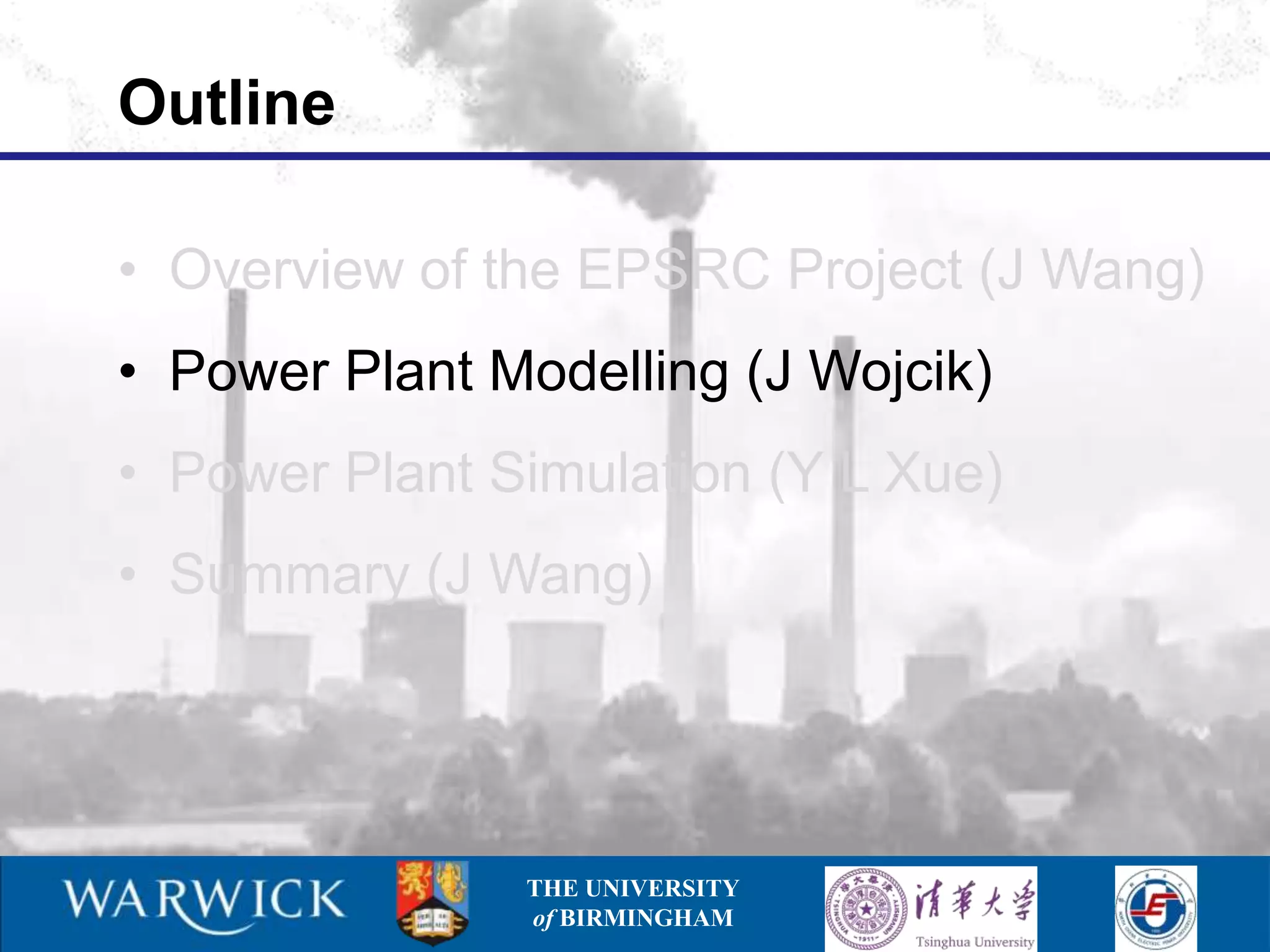
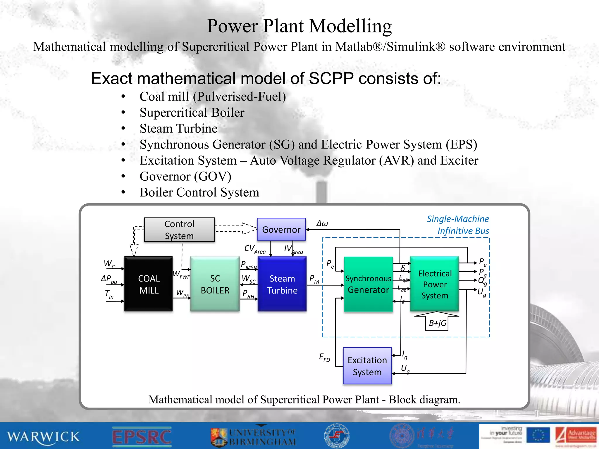
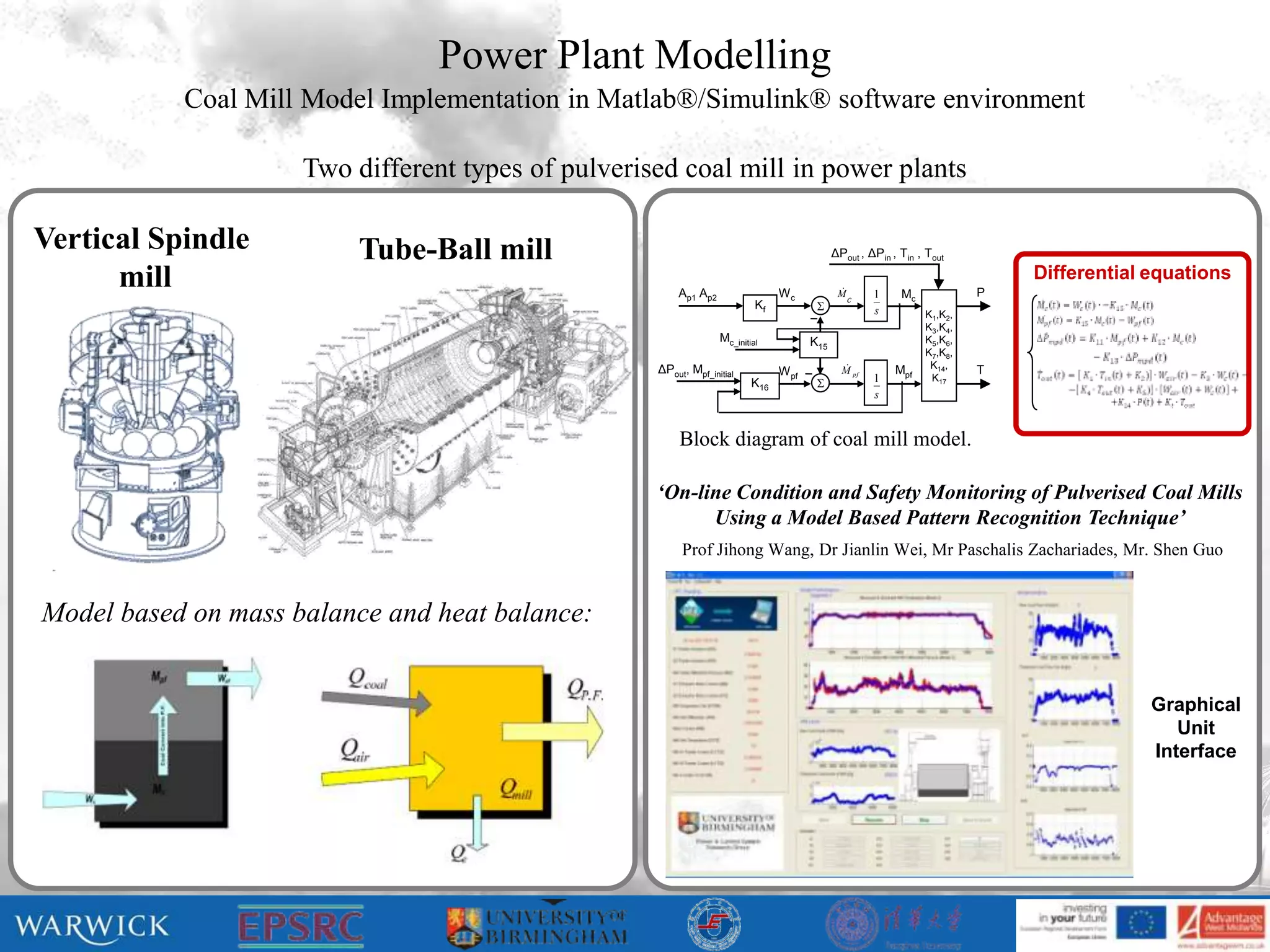
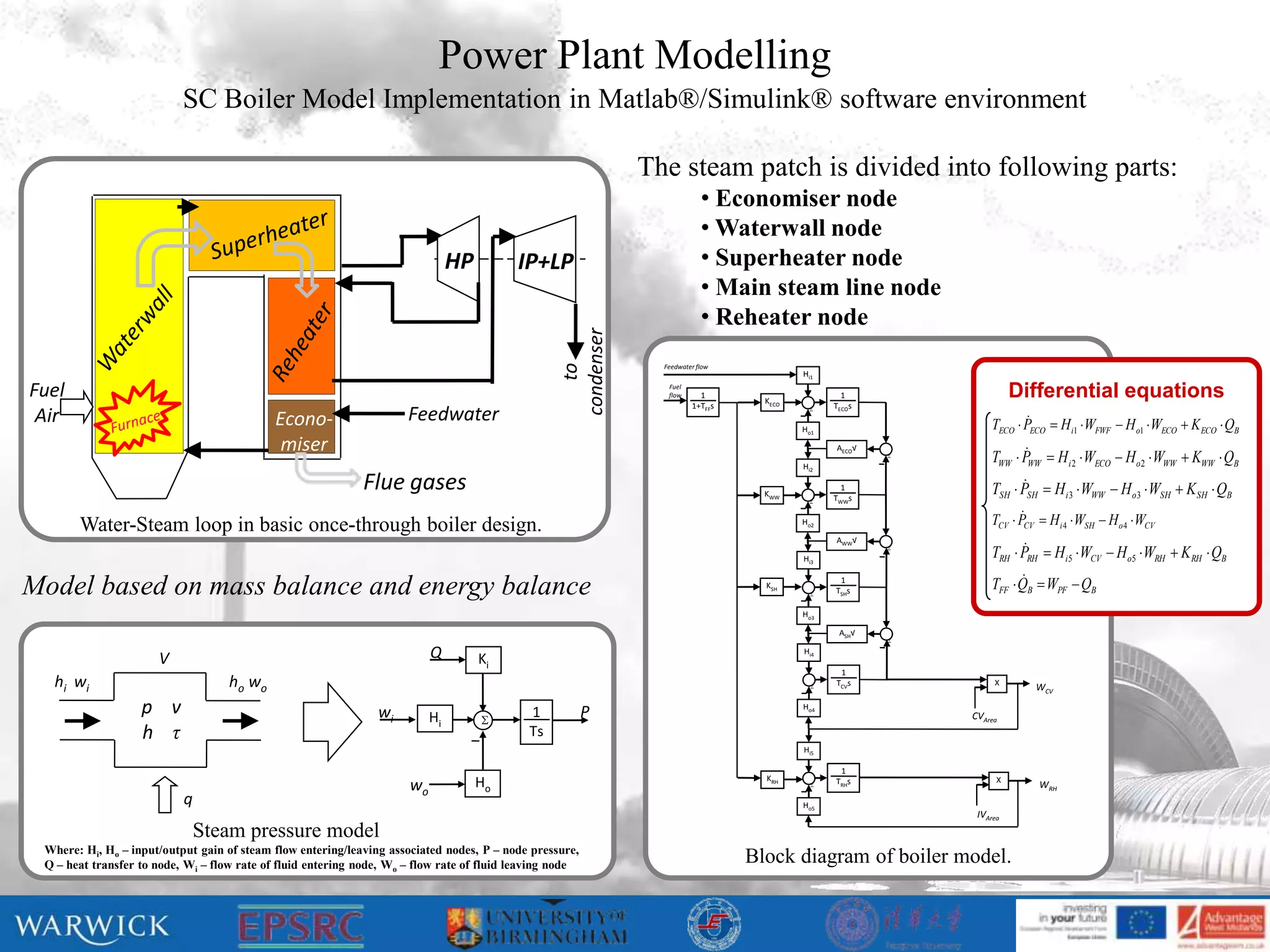
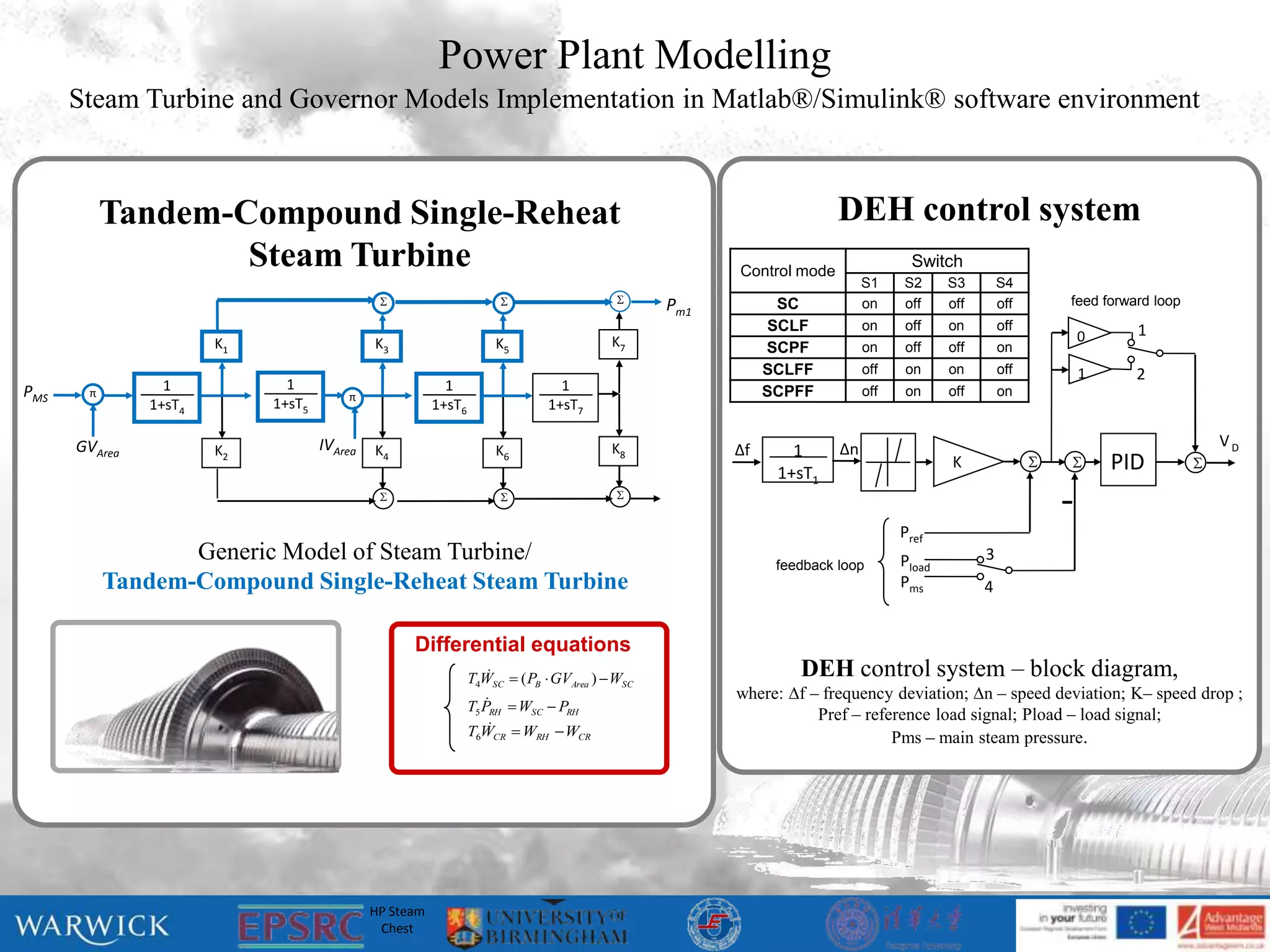
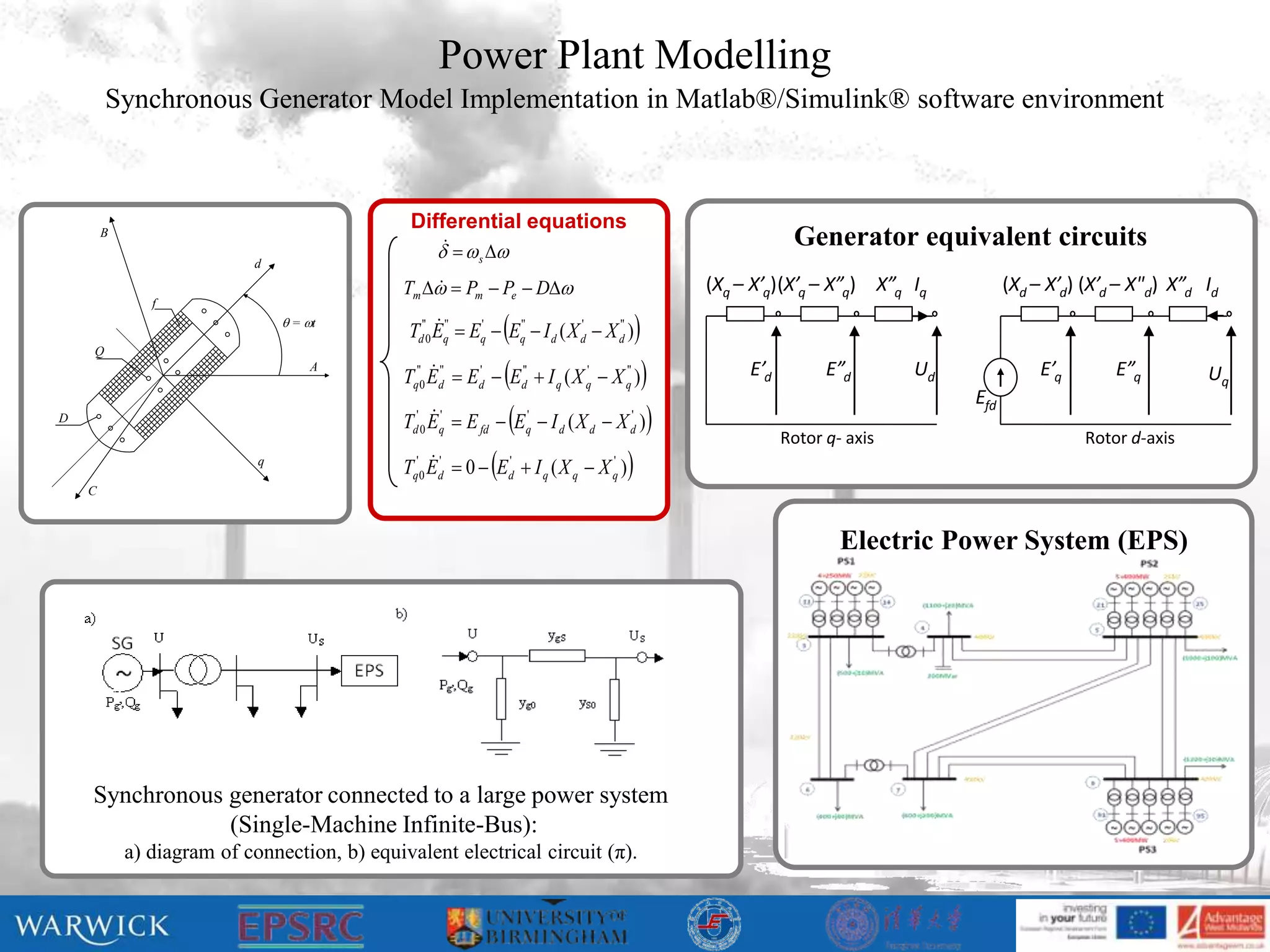
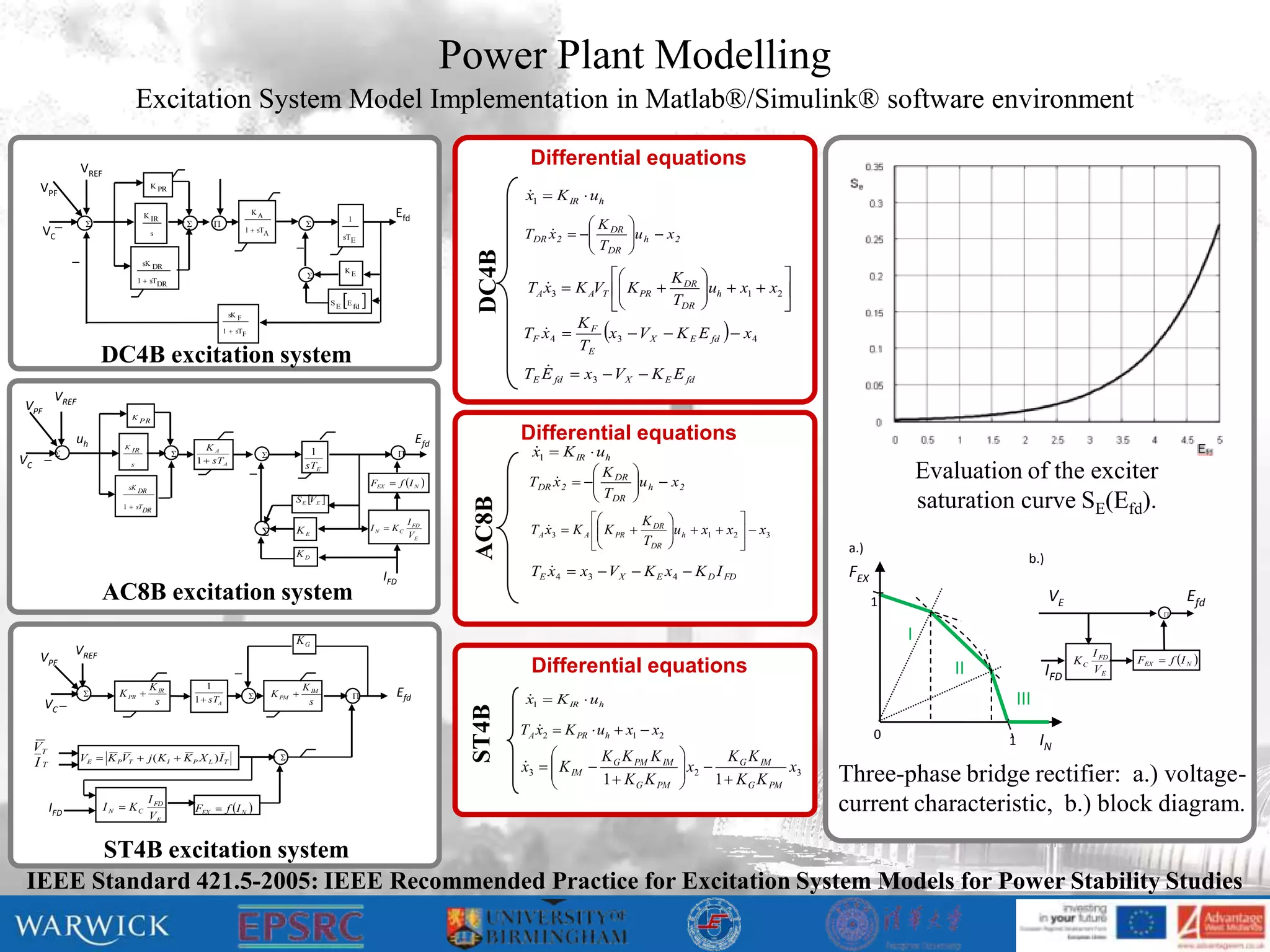
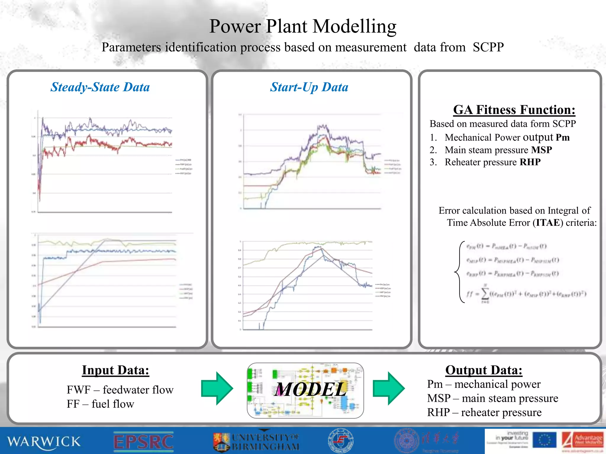
This document provides an overview of a workshop on mathematical modelling and simulation of power plants and CO2 capture. [1] It discusses modelling of supercritical coal-fired power plants, including models of the coal mill, supercritical boiler, steam turbine, and synchronous generator. [2] The models are implemented in MATLAB/Simulink and include differential equations representing the various components. [3] The workshop aims to understand the dynamic responses of supercritical power plants and investigate strategies to improve their ability to respond quickly to changes in electricity demand as required by grid codes.


![Hicheel de.blogspot.com [хөдөлмөрийн аюулгүй ажилгааны зааварчилгаа]](https://cdn.slidesharecdn.com/ss_thumbnails/hicheelde-blogspot-com-130420105559-phpapp02-thumbnail.jpg?width=640&height=640&fit=bounds)


