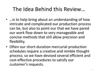
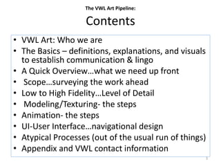
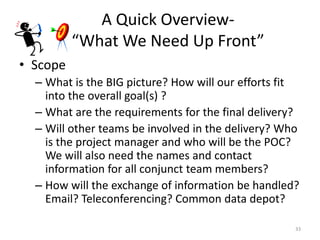
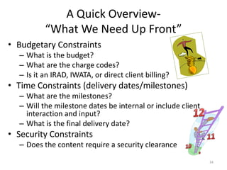
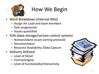
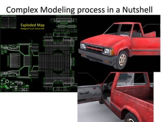
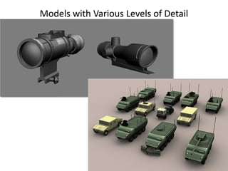
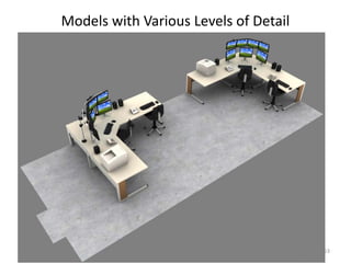
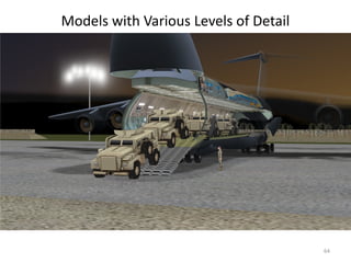
SlideShare a Scribd company logo
The VWL Art Pipeline:
An Illustrated Review
of our Art Production Process
1
The Idea Behind this Review…
• …is to help bring about an understanding of how
intricate and complicated our production process
can be, but also to point our that we have pared
our work flow down to very manageable and
concise methods that still allow precision and
flexibility.
• Often our short-duration mercurial production
schedules require a creative and nimble thought
process; so we have devised several efficient and
cost-effective procedures to satisfy our
customer’s requests.
2
Contents
• VWL Art: Who we are
• The Basics – definitions, explanations, and visuals
to establish communication & lingo
• A Quick Overview…what we need up front
• Scope…surveying the work ahead
• Low to High Fidelity…Level of Detail
• Modeling/Texturing- the steps
• Animation- the steps
• UI-User Interface…navigational design
• Atypical Processes (out of the usual run of things)
• Appendix and VWL contact information
The VWL Art Pipeline:
3
VWL ART TEAM
• Specialized in game technology art: virtual products
designed to be implemented in “real time”
• Work in strong alliance (practically a symbiotic
relationship) with the Software Development,
Instructional Design, the QA (Quality Assurance) Teams,
Business Development, and Administration.
• Cross-spectrum occupational demands… our work
encompasses wider dimensions than typical “Multimedia
Engineer” job descriptions…we are often delegated
duties that embrace production requirements of :
– 3D modelers, Texture Artists, Animators, Illustrators, Storyboard
Artists, UI Designers, Film Editors, Film Compositors, Level Designers,
Sound Engineers, Special Effects Artists, etc…
4
Remedial 3D Aesthetics
• In order to better understand what we do…it
might be good to clarify a few terms and
concepts:
– 3D vs. 2D
– Animated vs. immobility
– 1st person , 3rd person, aerial strategic viewpoint, “free-
flying” or “no clip” mode
– Real time vs. rendered
– Simulations, Games, & Virtual Worlds
5
3D vs. 2D
• 2D is 'flat', using
the X & Y
(horizontal and
vertical) axis‘
• the image has
only two
dimensions so if
a 2D image is
turned to the
side, it
becomes a line
• 3D adds the “Z”
dimension. This
third dimension
allows for
rotation and
depth.
• It's essentially
the difference
between a
painting and a
sculpture
2D and 3D refer to the actual dimensions in a computer's workspace
3D
2D
x
z
y
y
x
6
Animated 3D Models
• 3D Studio Max is the animation
software of choice for VWL
• Computer animation is really just a
sequence of “keyed” poses…the
software creates the transitions or
“tweens” to join or bridge these poses
together
• For film or video these animations are
“rendered” and can only be played
back in a player…there is no
navigation or player reciprocity
involved
• For games or interactive media,
animations are played back after they
have been “triggered” (an event that
reacts to a player’s actions )
• Animation is a very costly endeavor
…it can easily consume significant
amounts of time and budget
3D models can be imbued with movement, but this comes at a high expense of time & money.
7
Interactive Points of View
• 1st person- the player’s POV…action seen from the roaming
camera point of view. Usually arms/hands will be the only
viewable part of the player; these appendages are seen at
the bottom of the navigation window and provide the
player with a means to interact with the environment
• 3rd person- action and navigation seen as over the shoulder
of an interactive avatar stand-in
• Strategic viewpoint- birds view…typically the playing field is
seen from a top-down/high-distance POV…the player has a
greater ability to observe multiple “avatars”, vehicles or
weapons and strategically control them at will
• No clip mode- freely roaming like an apparition…1st person
without constraints…able to float through walls or
surfaces…sometimes called the “God Mode”. Often this
method is used to set up levels in the game “editor”
8
Interactive POV
9
1st Person Point Of View …UltiSim/Ogre
3rd Person Point Of View…Crytek game engine
Interactive POV
10
Interactive POV
Strategic and Free-roaming Points Of View
11
While 1st and 3rd person POV allows the
player to be immersed into the
action…down on the playing field, a
strategic POV places you high above it, and
feature a combination of tactical and
strategic considerations. From this vantage
point, the player can control multiple
actions of individuals or groups. Familiar
games using this perspective would be Star
Craft, War Craft, Civilization, or the Sims.
Real-time vs. Rendered
• Real-time implies creating synthetic/graphic images fast enough on the
computer so that the viewer can interact with a virtual environment
– Heavily constrained to the limitations of the hardware or software being
utilized
– Typically content is created with this constraint in mind…assets are made with
the lowest level of quantity/complexity/quality in mind, so that the graphics
can be displayed or rendered “on the fly”
• “Offline rendering” is used to create realistic images and movies…it occurs
through a series of still images, that are stitched (or edited) together into a
non-interactive video
– used mainly in the film industry to create high-quality renderings of lifelike
scenes
– performance is only of second priority…however, the need for very high-
quality and diverse effects requires that offline rendering needs a lot of
flexibility in time and computer processing.
– A very complex scene can require a series of interconnected computers
(known as a render farm) to process over several days…and require very large
computer storage. Editing is also a very arduous time consuming process.
12
Real-time vs. Rendered
Offline Rendered
Spartan or restrained use of polygons to
define the model’s surface…typically textures
(diffuse and bump mapped) will make up for
the abbreviated geometry usage
Denser use of polygons to define
the model’s surface…textures
(diffuse and bump mapped) can
also be used …although rendering
time will be impacted with
increased textural or polygonal
budgets
13
Simulations, Games, & Virtual Worlds
• Simulations are a reenactments of various activities
from "real life" in the form of a game for various
purposes: training, analysis, or prediction. Well-
known examples are war games, business games,
and role-play simulation.
• A simulation’s most advantageous feature is the
scenario where dangerous tasks or life-threatening
settings would be prohibitive or impossible to stage
without inflicting bodily harm or irreparable damage
(physical or economic) to inventory or structures.
14
Simulations, Games, & Virtual Worlds
• Games (aka serious games) are designed for a primary purpose other
than pure entertainment.
• The "serious" adjective is generally appended to refer to products used
by industries like defense, education, scientific exploration, health care,
emergency management, city planning, engineering, religion, and
politics.
• Games are typically designed for engagement on personal computers,
distributed as individualized (self-paced) training, and typically more
cost efficient for the user (single-use application).
• Games range from relatively simple or casual to very complex massively
multi-user operations. Their functionality is just as broad…from their
power to mimic convincing “real life” physics…to keenly agile AI
(artificial intelligence)…to convincing realistic human modeling &
motion…to their use of personal control devices.
15
Simulations, Games, & Virtual Worlds
• A Virtual World is a computer-based simulated environment intended for its
users to inhabit and interact via avatars in real time.
• These avatars are usually depicted as textual, two-dimensional, or three-
dimensional graphical representations.
• Most virtual worlds allow for multiple users and are not limited to games
(specified scenario solving). Depending on the degree of immediacy presented,
VWs can encompass computer conferencing and text based chatrooms *
• Massively multiplayer online games commonly depict a world very similar to
the real world, with real world rules and real-time actions, and communication.
Players create a character to travel between buildings, towns, and even worlds
to carry out business or leisure activities.
• Graphics are downplayed to prevent streaming data (from a potentially large
audience) from choking. Virtual worlds are noticeably less robust than
simulations or games…typically these arenas do not have dynamic shadows,
large textures or polygon budgets, particle effects, or fluid avatar motion.
* site on the internet where a number of users can communicate in real time (typically one dedicated to a particular topic
16
Simulations
17
Games
Casual style serious game designed for Lockheed Martin Security
training
18
Virtual Worlds
Afghanistan – Forterra Game Engine
19
Virtual Worlds
Lockheed Martin Center for Leadership Excellence- Icarus Game Engine
20
Now…Let’s begin with the Basics *
• 3D Models are computer generated (CG) objects that
consists of points (vertices), lines (edges), and surfaces
(polygons or triangles). All are derived from
mathematical computations and then visualized as
interconnected series of lines and curves called a mesh.
• Consider a mesh as the ultimate Connect-The-Dots
exercise…merely envisioned in 3D.
• The following slides will breakdown of a mesh into its
integrated components and describes the procedures
that transfuse it with a sense of realism
*Feel free to skim ahead if you’ve heard this all before
21
Vertex/vertices
•Points that are used to define corners or intersections of geometric shapes
•Typically a point common to three or more sides
•Associated with three spatial coordinates (x-axis, y-axis, and z-axis)
x
z
y
22
Introducing lines to create edges
•Connect the dots and you have the framework for a three dimensional (3D) Computer Generated (CG) object
•These connective lines are often denoted as edges; surfaces can be generated over top and within of these lines to
give the impression of a solid mass…these surfaces are known as polygons
x
z
y
23
Polygons and Triangles
•Polygons are 3 or more sided “faces” or surfaces…triangles are specific to only 3 sides
•Some applications which distinguish between triangle-based geometry and polygonal geometry will report polygon count
differently between these two object types (3dsmax, for instance)
•The difference may only be one of semantics, but it becomes important if you're making models for a game (since game
engines triangulate everything)
•Triangle/polygon count is very important…geometry budgets should not exceed the target application… EXCESSIVE POLYGONAL
COUNTS CAN DRASTICALLY SLOW CALCULATIONS (frame render rates & interactions)
•Surfaces are colored typically with a default material (color)
x
z
y
24
UVW mapping- Planar
•UVW Mapping defines the texture coordinates of a 3D object…or rather, the spatial relationship between a 2D image and the
“skin” of the 3D surface.
•UVW refers to coordinates in the object's own space, as opposed to the XYZ coordinates that describe the scene as a whole.
•However, the U, V, and W coordinates parallel the relative directions of X, Y, and Z coordinates. If you look at a 2D map image,
U is the equivalent of X, and represents the horizontal direction of the map. V is the equivalent of Y, and represents the
vertical direction of the map. W is the equivalent of Z and represents a direction perpendicular to the UV plane of the map
•The simplest method of texture application is planar mapping (seen above)…put simply, the texture is applied to a flat
surface using one of the 3 coordinates as a directional guide
•This surface can be applied in a simple procedural way that requires little user input or refined applications…such as planar or
box mapping (next slide)…or more complicated methods such as shaders.
Texturex
z
y
25
Mapping Parameters: Box Mapped Textures
•When Box mapping is applied to a selected object, the software maps each polygonal “face” to the side of the object
(in this example literally a box) that most closely matches its orientation.
•Box mapping is best applied to box-shaped objects or object parts that are oriented directly to one of the xyz axes
•Limitations: All sides will have consistent orientations. If
Box Mapped
x
z
y
Texture
26
Mapping Parameters: Textures mapped cylindrically and spherically
•When cylindrical mapping is applied to a selection, the software maps each face to the side that most closely
matches its cylinder orientation. For best results, use this type of mapping should ideally be used only with cylinder-
shaped objects or object parts.
•Limitations: Each cylindrical “cap” must be mapped separately from the sides or swirling will take place.
•When spherical mapping is applied to a selection, the software maps each face to the side that most closely matches
its sphere orientation. For best results, use this type of mapping should ideally be used only with spherical objects or
object parts
•Limitations: Pinching will occur along both axes, and the texture will become distorted…special adjustments must be
made in the 2d image to neutralize this particular type of map warping.
Spherical MappingCylindrical Mapping
x
z
y
27
Textures applied as if it were “unwrapped” or a “pelt”
•Each planar surface is applied individually
•The “pelt” is generated from a 3D software program such as 3DSMax or Maya using a plug-in application
•Typically the 3D software will generate the unwrapped surface in a random pattern…the artist is left to rearrange and interlink
each planar surfaces into a reasonably workable state
•The number of polygons and the complexity of the surface slows down this “remapping” or “planar repositioning” procedure
down exponentially. Essentially, the more complex the model is…the more time it takes to map
•Shadowing is based on the lighting arranged within the 3D software…often times these darkened surface will need to be tweaked
UVW Mapped Unwrapped Texturex
z
y
1024 x 1024 pixels
28
Textures applied as if it were “unwrapped” or a “pelt”
•The intricate surface undulations of the human face make the mapping and texturing process a very
complex and artful procedure
•After the 3D software creates the unwrapped base texture a series of photographs are blended together
to form one congruent surface map
•Special care must be paid to subtle variations of color, lighting/shading, and tactile surfacing.
•Seam must also be invisible when reapplied to the model…in particularly any adjoining edges
•Eyes are applied separately to allow rotation within the eye socket
Head UVW Mapped Unwrapped Texture
x
z
y
2048 x 2048 pixels
29
Here is a nutshell explanation for laying out complicated UVs; imagine disassembling a clock radio…then arranging each piece in a orderly pattern on a
sheet…keeping in mind you must keep up with how each part relates back to each other…because you have to paint each one later…that’s how it is 
Mapping Parameters: Bump Mapped Textures
•Just as it name implies, a “bump” map gives the indication of a raised surface within the texture…when lit appropriately it
responds to the direction of a light source.
•Textures are based on a black and white height map…computations of height are derived from the grade of black or white.
White is typically read as the highest level in the texture…black is seen as the recessed part of the texture
•Edges of the “raised” surfaces have highlights and shadowing…but without a true distortion of the planar surface. This
process is a procedural trick that helps decrease computations and rendering time (since additional geometry/polygons are
not utilized)
•Bump and normal maps respond to the interactive lighting within a game engine
•Most game engines/interactive environments…(but not all)…are able to make use of this process within their “shell”
Bump Mapped Surface
x
z
y
Bump mapped TextureNon-mapped Surface
30
Mapping Parameters: Normal Mapped Textures
•In 3D computer graphics, normal mapping is also a technique used for bump mapping, however its primary purpose
is to add details without using more polygons.
•A common use of this technique is to greatly enhance the appearance and details of a low polygon model by
generating a normal map derived from a high polygon model.
•Basic normal mapping can be implemented in any hardware that supports palletized textures. Games for the Xbox
360 and the PlayStation 3 rely heavily on normal mapping. VWL’s UltiSim also supports this technology.
•Side bar trivia: Interactive normal map rendering was originally only possible on PixelFlow, a parallel rendering
machine built at the University of North Carolina at Chapel Hill.
Bump Mapped Surface
x
z
y
Normal mapped Texture
31
The Art Pipeline Process
A Succinct Description of our Creative Development
32
A Quick Overview-
“What We Need Up Front”
• Scope
– What is the BIG picture? How will our efforts fit
into the overall goal(s) ?
– What are the requirements for the final delivery?
– Will other teams be involved in the delivery? Who
is the project manager and who will be the POC?
We will also need the names and contact
information for all conjunct team members?
– How will the exchange of information be handled?
Email? Teleconferencing? Common data depot?
33
A Quick Overview-
“What We Need Up Front”
• Budgetary Constraints
– What is the budget?
– What are the charge codes?
– Is it an IRAD, IWATA, or direct client billing?
• Time Constraints (delivery dates/milestones)
– What are the milestones?
– Will the milestone dates be internal or include client
interaction and input?
– What is the final delivery date?
• Security Constraints
– Does the content require a security clearance
34
How We Begin
• Work Breakdown (Internal Wiki)
– Assign Art Lead and team members
– Task assignments
– Assets quantified
• SVN (data storage/version control system)
– Nomenclature (asset naming protocol)
– Documentation
– Resource Availability /Data Capture
• Delivery Defined
– Level of Detail
– Format/engine
– Level of functionality/interactivity
35
Level of Detail
36
The Level of Refinement…
• …that can be added is really dependant on the budget and
milestones. Depending on the level of detail desired, refinement
can really be elaborate or succinct.
• High LOD is not appropriate (or possibly affordable) for many
projects…questions to ask are:
• What is the duration? How short are the milestones? When is the final
deliverable due?
• Is the higher level of detail necessary to accomplish the scenario’s
training/goals?
• Can the target user computer work withstand all of the bells and
whistles? Will there be appropriate processing power?
• How close will the player be in proximity to the interactive elements?
• Will there be avatar or objects animations?
• A carefully deliberated scope will guide us towards the most
appropriate treatment….this is why pre-production planning is
crucial.
37
Low Poly Modeling
• $...lowest cost of creative resources
• Timeframe defined by hours or days
• Low polygonal count
• 1 low resolution texture over entire model
• Intended to be seen far away from the
camera
• minimal…if any…animation
38
Low Level of Detail
Defines the shape of the structure with
the lowest number of polygons as
possible
This in turn allows the highest number
of models to populate the scene
without causing real-time rendering
issues
A medium sized texture can be applied
to the surface to enhance the model
and adjust for missed polygonal details
Lighting can be a resource hog…so
alternative means can be used to elude
to a light source. Ambient Occlusion
bakes shadows into the texture to
ameliorate the illusion of light.
39
Mid Poly Modeling
• $$$
• Timeframe defined by days or weeks
• 5-10 times the polygonal count of above model
• 3 (or more) textures with moderate-range
resolution and size
• Seen from a medium proportional distance from
the camera POV
• medium to high strata of animations/interactivity
• Less is more…a good texture can make up for the
diminished number of polygons
40
Mid-Level Poly Modeling
Models at this level are deceptively
complex…while in truth, each model only
possesses a moderate amount of polygons.
The illusion of complexity is achieved
through a series of very detailed and
precise textures mapped onto the
surface…the object’s skin
The engine is often limited in
rendering capacity…typically these
particular scenes are suitable to run
on mostly low-end computers or for
web-delivery. Polygonal and textural
budgets are restrained, so artwork has
to be created with these constraints
in mind
41
High Poly Modeling
• $$$$$+
• Timeframe defined by months (potentially years)
• 20 times the polygonal count of low-res model
• Multiple high resolution textures…potentially with
specialized mapping (surface/texture) setups
• Can be seen close-up (high range of interactivity)
• Facial animations factor in some of the highest
resource expense of time and money
• Typically utilized in conjunction with high-end game
engines such as Epic Games’ Unreal 3, Crytek’s
CryEngine 2, or Valve Software’s Source.
42
Higher Level of Detail
•This project was a Live Fire Virtual Trainer; this screen capture depicts an interactive scene created with a
moderately high polygonal budget using Autodesk’s 3DSMax. It was rendered within the Unreal 2 game engine.
•Textures are large and detailed…lighting, shadows, & objects are capable of acting on or influencing each other
within the environment.
•This “actual sized” scenario was devised with AI capabilities to help the learner feel immersed within the scene;
this is only one of multiple images that are projected onto specialized walled screens that envelop the player
inside a virtual environment.
•Licensing for game engines can be very costly and would require large project budgets
43
Higher Level of Detail
This model of a high-tech rifle scope was used in an interactive training
simulation. It needed to be very high-res because it would be viewed very
close to the screen…if it had a lower resolution it would look too blocky.
44
Modeling Process
45
Modeling
• BLOCKING OUT
–Data Capture/Reference
–Lowest level of detail…rudimentary
placeholders
–Space defined
–Scale
–Elementary interactivity
46
BLOCKING OUT- Data Capture/Reference
• Data capture
– Photographic documentation of assets on-site
– Images from internet search, library scans,
• 3D CAD data, blueprints, topographical layout, or other
technical manuals/drawings
– When working with 3D CAD data we strip down the model’s
polygonal count to an operable level for real-time deployment
– When creating complex mechanical or structural visualizations,
other assorted 2D technical information is often used in order to
preserve a high level of precision
• Storyboards have often proven to be an effective means to
communicate motions, scenic layout, interactive complexities,
and sequential actions
47
Data Capture/ReferenceDDG
Generator Room
48
Here you see a series of documentations
& illustrations that can help guide the
creative process
Data Capture/ReferenceDDG
Generator Room
49
BLOCKING OUT- Rudimentary placeholders
50
BLOCKING OUT- Rudimentary placeholders
51
BLOCKING OUT- Rudimentary placeholders
52
BLOCKING OUT- Rudimentary placeholders
53
BLOCKING OUT -Defining Space and Scale
54
BLOCKING OUT- Interactivity
55
Storyboard Sequence
56
Modeling
• REFINEMENTS
– Determination by scope/budget/milestones
– Image/data reference
– Extended surfacing…polygonal enhancement
– Texturing
– Lighting/ambient occlusion
– Functionality fine-tuned (coordinated efforts with
development and QA)
57
Modeling- Refinement
58
Modeling- Refinement
59
Complex Modeling process in a Nutshell
Blocked out Scene
1st stage of refinement
60
Complex Modeling process in a Nutshell
Exploded Map
Realigned Truck Texture Pelt
61
Models with Various Levels of Detail
62
Models with Various Levels of Detail
63
Models with Various Levels of Detail
64
Modeling Process…Avatar Head
• Creating an avatar is very complicated
• It involves many complex and difficult manipulations
• The following is a brief coverage of the process of
modeling an avatar’s (CG animated) head
• This is just an encapsulation…the idea is to
give you a sense of the level of detail
the process involves…much of the various
intricacies have been left off in order to
expedite the explanations
65
Data Capture
• We need multiple angled shots:
– to help derive the contours, size
and shapes of the model’s facial
features
– to utilize as textures…after a bit of
heavy photo manipulation, an
unwrapped surface will be
reapplied as the avatar’s “skin”
• The photos need to be created
with diffused light…heavy
shadows impede the texture
blending procedure and create
unsightly “dirty” areas
• Unlike compositing…a green
screen backdrop is not
desirable….a neutral white
background will not radiate
over the model and alter the
overall skin tone
66
Sculpting a Bona Fide Facsimile
• the modeler uses the multiple
photographic angles to help “trace”
out the various idiosyncratic facial
nuances of the subject’s likeness
• This procedure can appear to be
deceptively simplistic…to secure an
authentic looking representation the
modeler must constantly maneuver
between all of the angles to ensure
that the bone structure and
musculature is carefully aligned. This
requires a high degree of anatomical
knowledge, software mastery, &
artistic dexterity
• To add to the mix the “edging” of
each polygon needs to mimic the
muscular layout of the face…this
procedure helps minimize unrealistic
or unconvincing expressions and
prevents edge “crimping”
67
Flayed Flesh…Unwrapping the Mesh
• Once the head mesh has
been created, the mapping
procedure can occur
• Mapping guides the
application of texturing
(surfacing the
model)…UVW unwrapping
is the most common
method to apply to a face
or head
• Basically, the face is
“flayed” or “peeled “out
onto a flat plane…and later
reapplied back onto the 3d
mesh
68
Creating the Unwrapped Head Texture
• Using Photoshop, the texture is slowly
blended together
• The flayed template helps guide how
each angle is placed down…shadows are
minimized and multidirectional
…undulated parts of the skin and hair
are diligently stitched together into a
uninterrupted texture
• Adjoining ends must be able to meet
back together without creating an
obvious seam 69
Creating the Unwrapped Head Texture
flayed template with mesh overlay
70
Mapping & Applying the Unwrapped Head Texture
• Testing is constantly done to make sure exact alignment has occurred…the modeler must keep PS
and Max open simultaneously, so any obvious or subtle adjustments can occur
• Typically the eyes are textured as a separate object…since they need to rotate within the
sockets…the eye will often be placed into the facial texture (off to one side) and reapplied as a
frontal planar map. Careful attention must be made to the angle of any highlights or shadowing
71
Mapping & Applying the Unwrapped Head Texture
• As you can see by the
illustration to the right, the
texture has been overlaid back
over the mesh…edges are left
visible during this stage to help
with the alignment of individual
components…such as the nose,
mouth, hairline, ears, etc…
72
Voila! The End Results
• Success! Depending on
the context…the avatar
has closely mimicked its
real life counterpart
• Of course this brief
description does not
include the modeling or
texturing of the full
body, and it also does
not include the
extraordinary effort it
will take to animate the
avatar, but it does give
you a generalized
understanding of the
organic modeling
process
73
Troubleshooting: Getting Around a Lack of ReferenceBP
Operator’s
Essentials
74
Animation Demystified
75
Setting up for Animations
• As with modeling the level of detail needs to be determined up
front…along with a desired lists of motions.
• LOD also depends on whether or not the animation will be of an
avatar or object…also number & the duration of the motions
• For example - a mechanical crane arm is to be animated…first the
motion must be analyzed:
– How many frames are needed?
– How many parts will be moving?
– How rapid will the motion be?
– What is the range of motion (any constraints to the rotation or angles)
– Will there be any special effects? (such as sparks or drips)
• Avatars need to be modeled appropriately with motion in mind…
– edge loops must be laid out in such a manner that doesn’t deform the mesh
in an unnatural manner…facial distortions are easily perceived
– Inappropriate bends in the knees, arms or face can produce crimping or odd
looking twisting of the mesh
– Baggy clothes or draped material requires extreme modifications
76
Animation
• Rigging
– Skeletal animation incorporates the use of “bones”? They
function much like their real life counterparts by adding
support and allowing movement of the model.
– Each bone in the skeleton is associated with some portion
of the character; “skinning” is the process of creating this
association. The idea is that the bones affix to the model in
a logical manner.
– For example, in a model of a human being, the 'thigh' bone
would be associated with the vertices making up the
polygons in the model's thigh
– The more complex the moving parts…the more complex
the rig.
77
Skeletal “bone” system
78
A bone system, or
skeleton must be
custom built to fit
each individual
mesh if it is to be
posed or moved
The bone system
must have a logical
correlation to the
mesh with all joints
properly to bend
and move specific
areas
As seen in this
illustration, the
bones are color
coded and defined
by a white frame.
The mesh is
colored black
Skinning Process
79
Each vertex in the mesh must be assigned a number value…this
represents the degree of influence the bone has on the vertices.
For example, the vertices near the center of the “upper left arm”
bone should have a value close to 1 (this will have the greatest
influence on that bone) values will fall off closer to 0 as the
degree of influence gets further from the center. This dependent
linking must be followed for every bone and every vertex
As you can see, vertices are
color coordinated; hot colors
(reds) have the more
influence than the cooler
colors (orange and yellows)
What is Key Framed Animation?
• Computer animation borrows from traditional cel-animation, in that
central moments or positions are defined in each motion and “keyed”
(specified poses) within the animated time interval.
• The difference is that these “key-frames” are blended together as a
string of fluid and continuous motion by the computer…with
traditional it requires drawing individual frames to link the keys.
• Frame rates typically equal 30 frames per second for noninterlaced
video; in a real-time game frame is the time it takes to complete a full
round of the system's processing tasks. Frame rates vary from 30 to
100 FPS (frames per second )…depending on processor speed capacity
• Key-framed animation requires a keen attention to detail; with human
animation astute attention must be paid to behavior nuances and
individual idiosyncrasies to create a level of believability
• Milestone and budgetary constraints will dictate the level of
interaction and detail that can be accomplished
80
Key Framed Animation
81
Here, we see an example of motion curves and key-frames. The right upper
arm bone is selected and in the curve editor window we can see a graph of
that particular body part plus rotation over a designated time span
All the dots on the graph represent keys that were set to designate where that
particular body part should be located for each sequential time period
This example shows 40 frames of motion…which in this case is equivalent to a
little over 1 second of animation
Animation
• Motion capture, motion tracking or mocap are
terms used to describe the process of recording
movement from a live model and translating that
motion onto a digital model.
• It typically pertains to main body movements, but
it could also include subtle expressions of the
face and fingers; these subtle recordings are
often referred to as performance capture
• These movements are captures as individual We
have used this process on occasion, and the
software we use to stitch it all together is Motion
Builder
82
Motion Capture
83
Mo-cap rigging as seen in Motion Builder (skeleton, x-ray, and mesh).
All skeletal parts follow a hierarchical link from the “base node” (seen sticking out of
the skeleton’s back) that controls the entire structure
Animation
Sound or Lip Synching
• Lip synch technique is used to make an avatar appear to
speak. It involves figuring out the timings of the speech
(breakdown) as well as the actual animating of the
lips/mouth to match the dialogue track
• Avatars that speak are motion synchronized with a series
of elemental phonetic sounds…these are commonly
called phonemes. A viseme describes the particular facial
and oral movements that occur alongside the voicing of
phonemes.
• Visemes and facial expressions are accomplished through
one of two means: Morph targets or Facial bones/rigging
84
Lip Synching
85
Morph target animation is stored as a series of
vertex positions. In each key-frame of the
animation, the vertices are moved to a
different position… the vertices will move
along paths to fill in (blend) the blank time
between the key-frames
Skeletal (bone) facial systems mimic the
physical and anatomical characteristics of
bones, tissues, and skin to provide a realistic
appearance (e.g. spring-like elasticity).
Animation
• Rendering (cut scenes)
– Created in a “linear track”…once the sequence of
images have been compiled into a video, it
becomes fixed. Alterations are possible, but very
time consuming and costly
– Editing requires another skill set and knowledge of
particular software; VWL uses Adobe Premier and
After Effects for this task.
– File sizes are typically large (especially with higher
fidelity), so storage and playback on slower
computers can be an issue
86
Animation
• Real time/Interactive
– Real time avatar animations are often created as
individual “looped” motions(the last frame lines up
with the first frame…so there is an illusion of
continuous motility) and saved as a digital file
– These preset motions are “triggered” (set off) inside
the 3d environment by a user’s actions. These
triggered events are setup by the development team
– Typically there are multiple animation files (walk, run,
idle, etc…) that are stitched together “on the
fly”…meaning as it is needed in the scenario
– Again…budgets and milestones will dictate the LOD
and number of animations that will be needed
87
User Interface Design
88
UI Design
• Layout
– Typically we either fall back to concept pencil sketches or small blocked
out roughs using Photoshop
– This approach is heavily laden with close communication with the client,
clear analysis and short review is key to efficiency
– Several mock-up offer variable choices on color, scale, placement and
icon/button innovation within the page
• Photoshop refinement
– Finessing begins with adding details, reducing or elaborating on the color
scheme, final button or icon detailing, nailing down the border or frame
design, and final placement of components
– Then we devise the best means the chop out the components into the
most appropriate pieces for webpage utility
• HTML and Flash
– Since our primary functionality is a 3D shop, so HTML/Flash design is not
our mainstay. However, necessity is the rule and our team can more than
rise to the task of finding a way to deliver only outstanding results. This
usually means we work extremely close with the development team to
allow them to initiate any coding or scripting functionality.
89
UI Design
90This is a (UI) User Interface for a project designed to train oil refinery operators
Art Procedures out of the Norm
91
Atypical processes
• Digital Film Compositing/Editing
– Film compositing is the process of digitally assembling multiple
images to make a final image…typically this is seen in film and
television.
– This procedure is not our mainstay, however we have been
asked to work with LM Corporate to composite, edit, and
compile several “Ethics” training videos
– We use Adobe After Effects to layer the images together and
Adobe Premier to stitch the small vignettes (usually a few
seconds in length) together.
– Sound is also part of the editing process…however we do not
have the facilities to implement that specialized process
92
Digital Film Compositing/Editing
93
Atypical processes
• Concept Art
– Often this process begins with a simple pencil
sketch on particular tasks where we need to
generate ideas or require pre-visualization
(visualize scenes digital production work
begins)
– Typically this generates many ideas and only
one (or a merger of several) will find its way to
the prototype and eventually the final product
94
Concept art
95
VWL Team Bios
96
97
I have been working professionally in Art for 30 years with 14 years experience in game
development . My specialty is concept art/illustration and texturing for 3d models. I have a vast
network of Creatives…this has helped me assemble this brilliant team.
mark.a.smith@lmco.com
brad.d.acree@lmco.com
steven.brady@lmco.com
mark.lemmons@lmco.com
jason.powell@lmco.com
chris.seher@lmco.com
Mark Smith
(Marx Myth)
Multimedia Design Eng Mgr
Brad Acree
Multimedia Design Eng Sr
Steven Brady
Multimedia Design Eng
Mark Lemmons
Multimedia Design Eng Asc
Jason Powell
Multimedia Design Eng
Geoff Yarbrough
Multimedia Design Eng
Chris Seher
Multimedia Design Eng Stf
geoff.yarbrough@lmco.com
Brad has been in 3d for a number of years. We retrieved him from Central Florida University. He has
worked on many titles, Duke Nukem, Rugrats, and other numerous simulation developments.
Steven is a former student of mine at the School of Communication Arts. He is an excellent animator
but also is talented at modeling and texturing. He has previously worked in the graphics field too.
Mark is our most junior member, but he a bit of a savant in so many areas. He is also a former
student of mine and has worked in the game industry for 2 years. He is an extraordinary
modeler/texturer…our go to guy for game engine insights, and also leaps over tall buildings.
Jason is brilliant at modeling and drawing/painting. We retrieved him from a local game company.
He has a military background and an encyclopedia knowledge of weapons, vehicles, and military
processes.
Chris is our most senior artist/genius. His affable nature hides a brilliant and talented understanding
of all things 3D. He is a work horse and my go to guy for getting things done. We have had a long
relationship in production (2 other separate companies) and he is also a former student of mine.
Geoff has a long career in simulations and game development. He has been a key addition to the
team with his experience in modeling and animation. He also has a strong background in working
with scripting and code.
VWL Contacts
1140 Kildare Farm Road
Suite 200
Cary, NC 27511
919/469-9950
98
Richard Boyd
Program Management Director
Risa Larsen
Site Manager
Ken Lane
Software Development Manager
Frank Boosman
Program Management Director (Business Development )
Mike Lerg
Staff Business Development Analyst
Dave Navarro
QA Manager

More Related Content

What's hot

Animation
AnimationAnimation
Animation
Vasu Mathi
 
Animation
AnimationAnimation
Animation
Vasu Mathi
 
Animation
AnimationAnimation
Animation
Vasu Mathi
 
Bb 8 run - a star wars video game
Bb 8 run - a star wars video gameBb 8 run - a star wars video game
Bb 8 run - a star wars video game
Roberto Falconi
 
Animations
AnimationsAnimations
Animations
Adri Jovin
 
Serious games a proposal of taxonomy gacet11
Serious games a proposal of taxonomy gacet11Serious games a proposal of taxonomy gacet11
Serious games a proposal of taxonomy gacet11
CATTID "Sapienza"
 
BB8 RUN - A Star Wars video game
BB8 RUN - A Star Wars video gameBB8 RUN - A Star Wars video game
BB8 RUN - A Star Wars video game
Roberto Falconi
 
Advanced animation techniques
Advanced animation techniquesAdvanced animation techniques
Advanced animation techniques
Charles Flynt
 
Prayas session cgi & cga by – soumalya nandy
Prayas session cgi & cga by – soumalya nandyPrayas session cgi & cga by – soumalya nandy
Prayas session cgi & cga by – soumalya nandy
Tenet Systems Pvt Ltd
 
lecture1 introduction to computer graphics(Computer graphics tutorials)
lecture1 introduction to computer graphics(Computer graphics tutorials)lecture1 introduction to computer graphics(Computer graphics tutorials)
lecture1 introduction to computer graphics(Computer graphics tutorials)
Daroko blog(www.professionalbloggertricks.com)
 
Ai on video games
Ai on video gamesAi on video games
Ai on video games
Faria Priya
 
Introduction to Game Programming: Using C# and Unity 3D - Chapter 6 (Preview)
Introduction to Game Programming: Using C# and Unity 3D - Chapter 6 (Preview)Introduction to Game Programming: Using C# and Unity 3D - Chapter 6 (Preview)
Introduction to Game Programming: Using C# and Unity 3D - Chapter 6 (Preview)
noorcon
 
lecture4 raster details in computer graphics(Computer graphics tutorials)
lecture4 raster details in computer graphics(Computer graphics tutorials)lecture4 raster details in computer graphics(Computer graphics tutorials)
lecture4 raster details in computer graphics(Computer graphics tutorials)
Daroko blog(www.professionalbloggertricks.com)
 
3D Movie Presentation
3D Movie Presentation3D Movie Presentation
3D Movie Presentation
erAbhinavSinha
 
Trends in Computer Graphics
Trends in Computer GraphicsTrends in Computer Graphics
Trends in Computer Graphics
Sajal Maharjan
 
Introduction to Game Programming: Using C# and Unity 3D - Chapter 2 (Preview)
Introduction to Game Programming: Using C# and Unity 3D - Chapter 2 (Preview)Introduction to Game Programming: Using C# and Unity 3D - Chapter 2 (Preview)
Introduction to Game Programming: Using C# and Unity 3D - Chapter 2 (Preview)
noorcon
 
Virtual reality
Virtual realityVirtual reality
Virtual reality
chahat aggarwal
 
Introduction to Game Programming: Using C# and Unity 3D - Chapter 7 (Preview)
Introduction to Game Programming: Using C# and Unity 3D - Chapter 7 (Preview)Introduction to Game Programming: Using C# and Unity 3D - Chapter 7 (Preview)
Introduction to Game Programming: Using C# and Unity 3D - Chapter 7 (Preview)
noorcon
 
Project on ai gaming
Project on ai gamingProject on ai gaming
Project on ai gaming
Roshan Panday
 
AI Lecture 5 (game playing)
AI Lecture 5 (game playing)AI Lecture 5 (game playing)
AI Lecture 5 (game playing)
Tajim Md. Niamat Ullah Akhund
 

What's hot (20)

Animation
AnimationAnimation
Animation
 
Animation
AnimationAnimation
Animation
 
Animation
AnimationAnimation
Animation
 
Bb 8 run - a star wars video game
Bb 8 run - a star wars video gameBb 8 run - a star wars video game
Bb 8 run - a star wars video game
 
Animations
AnimationsAnimations
Animations
 
Serious games a proposal of taxonomy gacet11
Serious games a proposal of taxonomy gacet11Serious games a proposal of taxonomy gacet11
Serious games a proposal of taxonomy gacet11
 
BB8 RUN - A Star Wars video game
BB8 RUN - A Star Wars video gameBB8 RUN - A Star Wars video game
BB8 RUN - A Star Wars video game
 
Advanced animation techniques
Advanced animation techniquesAdvanced animation techniques
Advanced animation techniques
 
Prayas session cgi & cga by – soumalya nandy
Prayas session cgi & cga by – soumalya nandyPrayas session cgi & cga by – soumalya nandy
Prayas session cgi & cga by – soumalya nandy
 
lecture1 introduction to computer graphics(Computer graphics tutorials)
lecture1 introduction to computer graphics(Computer graphics tutorials)lecture1 introduction to computer graphics(Computer graphics tutorials)
lecture1 introduction to computer graphics(Computer graphics tutorials)
 
Ai on video games
Ai on video gamesAi on video games
Ai on video games
 
Introduction to Game Programming: Using C# and Unity 3D - Chapter 6 (Preview)
Introduction to Game Programming: Using C# and Unity 3D - Chapter 6 (Preview)Introduction to Game Programming: Using C# and Unity 3D - Chapter 6 (Preview)
Introduction to Game Programming: Using C# and Unity 3D - Chapter 6 (Preview)
 
lecture4 raster details in computer graphics(Computer graphics tutorials)
lecture4 raster details in computer graphics(Computer graphics tutorials)lecture4 raster details in computer graphics(Computer graphics tutorials)
lecture4 raster details in computer graphics(Computer graphics tutorials)
 
3D Movie Presentation
3D Movie Presentation3D Movie Presentation
3D Movie Presentation
 
Trends in Computer Graphics
Trends in Computer GraphicsTrends in Computer Graphics
Trends in Computer Graphics
 
Introduction to Game Programming: Using C# and Unity 3D - Chapter 2 (Preview)
Introduction to Game Programming: Using C# and Unity 3D - Chapter 2 (Preview)Introduction to Game Programming: Using C# and Unity 3D - Chapter 2 (Preview)
Introduction to Game Programming: Using C# and Unity 3D - Chapter 2 (Preview)
 
Virtual reality
Virtual realityVirtual reality
Virtual reality
 
Introduction to Game Programming: Using C# and Unity 3D - Chapter 7 (Preview)
Introduction to Game Programming: Using C# and Unity 3D - Chapter 7 (Preview)Introduction to Game Programming: Using C# and Unity 3D - Chapter 7 (Preview)
Introduction to Game Programming: Using C# and Unity 3D - Chapter 7 (Preview)
 
Project on ai gaming
Project on ai gamingProject on ai gaming
Project on ai gaming
 
AI Lecture 5 (game playing)
AI Lecture 5 (game playing)AI Lecture 5 (game playing)
AI Lecture 5 (game playing)
 

Similar to Vwl art pipeline explained----2

Cg notes
Cg notesCg notes
Cg notes
Singston_Albert
 
COMUTER GRAPHICS NOTES
COMUTER GRAPHICS NOTESCOMUTER GRAPHICS NOTES
COMUTER GRAPHICS NOTES
ho58
 
5 multimedia elements - animation
5   multimedia elements - animation5   multimedia elements - animation
5 multimedia elements - animation
Kelly Bauer
 
Virtual_Reality_New.pptx
Virtual_Reality_New.pptxVirtual_Reality_New.pptx
Virtual_Reality_New.pptx
BapuPradhan1
 
B. SC CSIT Computer Graphics Unit 5 By Tekendra Nath Yogi
B. SC CSIT Computer Graphics Unit 5 By Tekendra Nath YogiB. SC CSIT Computer Graphics Unit 5 By Tekendra Nath Yogi
B. SC CSIT Computer Graphics Unit 5 By Tekendra Nath Yogi
Tekendra Nath Yogi
 
HA5 – COMPUTER ARTS BLOG ARTICLE – 3D: The Basics
HA5 – COMPUTER ARTS BLOG ARTICLE – 3D: The BasicsHA5 – COMPUTER ARTS BLOG ARTICLE – 3D: The Basics
HA5 – COMPUTER ARTS BLOG ARTICLE – 3D: The Basics
hamza_123456
 
Create a Scalable and Destructible World in HITMAN 2*
Create a Scalable and Destructible World in HITMAN 2*Create a Scalable and Destructible World in HITMAN 2*
Create a Scalable and Destructible World in HITMAN 2*
Intel® Software
 
Artificial Intelligence in Gaming
Artificial Intelligence in GamingArtificial Intelligence in Gaming
Artificial Intelligence in Gaming
Anmol Sawhney
 
Graphics pdf
Graphics pdfGraphics pdf
Graphics pdf
aa11bb11
 
3D - The Basics
3D - The Basics 3D - The Basics
3D - The Basics
hamza_123456
 
HA5 – COMPUTER ARTS BLOG ARTICLE – 3D: The Basics
HA5 – COMPUTER ARTS BLOG ARTICLE – 3D: The BasicsHA5 – COMPUTER ARTS BLOG ARTICLE – 3D: The Basics
HA5 – COMPUTER ARTS BLOG ARTICLE – 3D: The Basics
hamza_123456
 
Meta 3D Studios Art Experience
Meta 3D Studios Art ExperienceMeta 3D Studios Art Experience
Meta 3D Studios Art Experience
Billy Joe Cain
 
HCI2015_09.pptx ghdjkl vsggfoojhvbnkiknccg
HCI2015_09.pptx ghdjkl vsggfoojhvbnkiknccgHCI2015_09.pptx ghdjkl vsggfoojhvbnkiknccg
HCI2015_09.pptx ghdjkl vsggfoojhvbnkiknccg
roddavijaypatel
 
virtual reality...............................
virtual reality...............................virtual reality...............................
virtual reality...............................
MeghaKulkarni27
 
Vfx PPT
Vfx PPTVfx PPT
Vfx PPT
Mit Shah
 
Virtual reality (vr) presentation
Virtual reality (vr) presentation Virtual reality (vr) presentation
Virtual reality (vr) presentation
Ranjeet Kumar
 
VIRTUAL REALITY PRESENTATION
VIRTUAL REALITY PRESENTATION VIRTUAL REALITY PRESENTATION
VIRTUAL REALITY PRESENTATION
Bello Adamu
 
Introduction to graphics
Introduction to graphicsIntroduction to graphics
Introduction to graphics
Sowmya Jyothi
 
Ancient world online
Ancient world online Ancient world online
Ancient world online
SeifElDeen3
 
MIL WEEK 6.pptx
MIL WEEK 6.pptxMIL WEEK 6.pptx
MIL WEEK 6.pptx
JesonAbejuela
 

Similar to Vwl art pipeline explained----2 (20)

Cg notes
Cg notesCg notes
Cg notes
 
COMUTER GRAPHICS NOTES
COMUTER GRAPHICS NOTESCOMUTER GRAPHICS NOTES
COMUTER GRAPHICS NOTES
 
5 multimedia elements - animation
5   multimedia elements - animation5   multimedia elements - animation
5 multimedia elements - animation
 
Virtual_Reality_New.pptx
Virtual_Reality_New.pptxVirtual_Reality_New.pptx
Virtual_Reality_New.pptx
 
B. SC CSIT Computer Graphics Unit 5 By Tekendra Nath Yogi
B. SC CSIT Computer Graphics Unit 5 By Tekendra Nath YogiB. SC CSIT Computer Graphics Unit 5 By Tekendra Nath Yogi
B. SC CSIT Computer Graphics Unit 5 By Tekendra Nath Yogi
 
HA5 – COMPUTER ARTS BLOG ARTICLE – 3D: The Basics
HA5 – COMPUTER ARTS BLOG ARTICLE – 3D: The BasicsHA5 – COMPUTER ARTS BLOG ARTICLE – 3D: The Basics
HA5 – COMPUTER ARTS BLOG ARTICLE – 3D: The Basics
 
Create a Scalable and Destructible World in HITMAN 2*
Create a Scalable and Destructible World in HITMAN 2*Create a Scalable and Destructible World in HITMAN 2*
Create a Scalable and Destructible World in HITMAN 2*
 
Artificial Intelligence in Gaming
Artificial Intelligence in GamingArtificial Intelligence in Gaming
Artificial Intelligence in Gaming
 
Graphics pdf
Graphics pdfGraphics pdf
Graphics pdf
 
3D - The Basics
3D - The Basics 3D - The Basics
3D - The Basics
 
HA5 – COMPUTER ARTS BLOG ARTICLE – 3D: The Basics
HA5 – COMPUTER ARTS BLOG ARTICLE – 3D: The BasicsHA5 – COMPUTER ARTS BLOG ARTICLE – 3D: The Basics
HA5 – COMPUTER ARTS BLOG ARTICLE – 3D: The Basics
 
Meta 3D Studios Art Experience
Meta 3D Studios Art ExperienceMeta 3D Studios Art Experience
Meta 3D Studios Art Experience
 
HCI2015_09.pptx ghdjkl vsggfoojhvbnkiknccg
HCI2015_09.pptx ghdjkl vsggfoojhvbnkiknccgHCI2015_09.pptx ghdjkl vsggfoojhvbnkiknccg
HCI2015_09.pptx ghdjkl vsggfoojhvbnkiknccg
 
virtual reality...............................
virtual reality...............................virtual reality...............................
virtual reality...............................
 
Vfx PPT
Vfx PPTVfx PPT
Vfx PPT
 
Virtual reality (vr) presentation
Virtual reality (vr) presentation Virtual reality (vr) presentation
Virtual reality (vr) presentation
 
VIRTUAL REALITY PRESENTATION
VIRTUAL REALITY PRESENTATION VIRTUAL REALITY PRESENTATION
VIRTUAL REALITY PRESENTATION
 
Introduction to graphics
Introduction to graphicsIntroduction to graphics
Introduction to graphics
 
Ancient world online
Ancient world online Ancient world online
Ancient world online
 
MIL WEEK 6.pptx
MIL WEEK 6.pptxMIL WEEK 6.pptx
MIL WEEK 6.pptx
 

Recently uploaded

AI + Data Community Tour - Build the Next Generation of Apps with the Einstei...
AI + Data Community Tour - Build the Next Generation of Apps with the Einstei...AI + Data Community Tour - Build the Next Generation of Apps with the Einstei...
AI + Data Community Tour - Build the Next Generation of Apps with the Einstei...
Paris Salesforce Developer Group
 
Welding Metallurgy Ferrous Materials.pdf
Welding Metallurgy Ferrous Materials.pdfWelding Metallurgy Ferrous Materials.pdf
Welding Metallurgy Ferrous Materials.pdf
AjmalKhan50578
 
Use PyCharm for remote debugging of WSL on a Windo cf5c162d672e4e58b4dde5d797...
Use PyCharm for remote debugging of WSL on a Windo cf5c162d672e4e58b4dde5d797...Use PyCharm for remote debugging of WSL on a Windo cf5c162d672e4e58b4dde5d797...
Use PyCharm for remote debugging of WSL on a Windo cf5c162d672e4e58b4dde5d797...
shadow0702a
 
LLM Fine Tuning with QLoRA Cassandra Lunch 4, presented by Anant
LLM Fine Tuning with QLoRA Cassandra Lunch 4, presented by AnantLLM Fine Tuning with QLoRA Cassandra Lunch 4, presented by Anant
LLM Fine Tuning with QLoRA Cassandra Lunch 4, presented by Anant
Anant Corporation
 
Software Engineering and Project Management - Introduction, Modeling Concepts...
Software Engineering and Project Management - Introduction, Modeling Concepts...Software Engineering and Project Management - Introduction, Modeling Concepts...
Software Engineering and Project Management - Introduction, Modeling Concepts...
Prakhyath Rai
 
CompEx~Manual~1210 (2).pdf COMPEX GAS AND VAPOURS
CompEx~Manual~1210 (2).pdf COMPEX GAS AND VAPOURSCompEx~Manual~1210 (2).pdf COMPEX GAS AND VAPOURS
CompEx~Manual~1210 (2).pdf COMPEX GAS AND VAPOURS
RamonNovais6
 
学校原版美国波士顿大学毕业证学历学位证书原版一模一样
学校原版美国波士顿大学毕业证学历学位证书原版一模一样学校原版美国波士顿大学毕业证学历学位证书原版一模一样
学校原版美国波士顿大学毕业证学历学位证书原版一模一样
171ticu
 
morris_worm_intro_and_source_code_analysis_.pdf
morris_worm_intro_and_source_code_analysis_.pdfmorris_worm_intro_and_source_code_analysis_.pdf
morris_worm_intro_and_source_code_analysis_.pdf
ycwu0509
 
Design and optimization of ion propulsion drone
Design and optimization of ion propulsion droneDesign and optimization of ion propulsion drone
Design and optimization of ion propulsion drone
bjmsejournal
 
Engineering Standards Wiring methods.pdf
Engineering Standards Wiring methods.pdfEngineering Standards Wiring methods.pdf
Engineering Standards Wiring methods.pdf
edwin408357
 
一比一原版(osu毕业证书)美国俄勒冈州立大学毕业证如何办理
一比一原版(osu毕业证书)美国俄勒冈州立大学毕业证如何办理一比一原版(osu毕业证书)美国俄勒冈州立大学毕业证如何办理
一比一原版(osu毕业证书)美国俄勒冈州立大学毕业证如何办理
upoux
 
Rainfall intensity duration frequency curve statistical analysis and modeling...
Rainfall intensity duration frequency curve statistical analysis and modeling...Rainfall intensity duration frequency curve statistical analysis and modeling...
Rainfall intensity duration frequency curve statistical analysis and modeling...
bijceesjournal
 
SCALING OF MOS CIRCUITS m .pptx
SCALING OF MOS CIRCUITS m                 .pptxSCALING OF MOS CIRCUITS m                 .pptx
SCALING OF MOS CIRCUITS m .pptx
harshapolam10
 
Computational Engineering IITH Presentation
Computational Engineering IITH PresentationComputational Engineering IITH Presentation
Computational Engineering IITH Presentation
co23btech11018
 
VARIABLE FREQUENCY DRIVE. VFDs are widely used in industrial applications for...
VARIABLE FREQUENCY DRIVE. VFDs are widely used in industrial applications for...VARIABLE FREQUENCY DRIVE. VFDs are widely used in industrial applications for...
VARIABLE FREQUENCY DRIVE. VFDs are widely used in industrial applications for...
PIMR BHOPAL
 
Generative AI Use cases applications solutions and implementation.pdf
Generative AI Use cases applications solutions and implementation.pdfGenerative AI Use cases applications solutions and implementation.pdf
Generative AI Use cases applications solutions and implementation.pdf
mahaffeycheryld
 
2008 BUILDING CONSTRUCTION Illustrated - Ching Chapter 08 Doors and Windows.pdf
2008 BUILDING CONSTRUCTION Illustrated - Ching Chapter 08 Doors and Windows.pdf2008 BUILDING CONSTRUCTION Illustrated - Ching Chapter 08 Doors and Windows.pdf
2008 BUILDING CONSTRUCTION Illustrated - Ching Chapter 08 Doors and Windows.pdf
Yasser Mahgoub
 
Advanced control scheme of doubly fed induction generator for wind turbine us...
Advanced control scheme of doubly fed induction generator for wind turbine us...Advanced control scheme of doubly fed induction generator for wind turbine us...
Advanced control scheme of doubly fed induction generator for wind turbine us...
IJECEIAES
 
IEEE Aerospace and Electronic Systems Society as a Graduate Student Member
IEEE Aerospace and Electronic Systems Society as a Graduate Student MemberIEEE Aerospace and Electronic Systems Society as a Graduate Student Member
IEEE Aerospace and Electronic Systems Society as a Graduate Student Member
VICTOR MAESTRE RAMIREZ
 
132/33KV substation case study Presentation
132/33KV substation case study Presentation132/33KV substation case study Presentation
132/33KV substation case study Presentation
kandramariana6
 

Recently uploaded (20)

AI + Data Community Tour - Build the Next Generation of Apps with the Einstei...
AI + Data Community Tour - Build the Next Generation of Apps with the Einstei...AI + Data Community Tour - Build the Next Generation of Apps with the Einstei...
AI + Data Community Tour - Build the Next Generation of Apps with the Einstei...
 
Welding Metallurgy Ferrous Materials.pdf
Welding Metallurgy Ferrous Materials.pdfWelding Metallurgy Ferrous Materials.pdf
Welding Metallurgy Ferrous Materials.pdf
 
Use PyCharm for remote debugging of WSL on a Windo cf5c162d672e4e58b4dde5d797...
Use PyCharm for remote debugging of WSL on a Windo cf5c162d672e4e58b4dde5d797...Use PyCharm for remote debugging of WSL on a Windo cf5c162d672e4e58b4dde5d797...
Use PyCharm for remote debugging of WSL on a Windo cf5c162d672e4e58b4dde5d797...
 
LLM Fine Tuning with QLoRA Cassandra Lunch 4, presented by Anant
LLM Fine Tuning with QLoRA Cassandra Lunch 4, presented by AnantLLM Fine Tuning with QLoRA Cassandra Lunch 4, presented by Anant
LLM Fine Tuning with QLoRA Cassandra Lunch 4, presented by Anant
 
Software Engineering and Project Management - Introduction, Modeling Concepts...
Software Engineering and Project Management - Introduction, Modeling Concepts...Software Engineering and Project Management - Introduction, Modeling Concepts...
Software Engineering and Project Management - Introduction, Modeling Concepts...
 
CompEx~Manual~1210 (2).pdf COMPEX GAS AND VAPOURS
CompEx~Manual~1210 (2).pdf COMPEX GAS AND VAPOURSCompEx~Manual~1210 (2).pdf COMPEX GAS AND VAPOURS
CompEx~Manual~1210 (2).pdf COMPEX GAS AND VAPOURS
 
学校原版美国波士顿大学毕业证学历学位证书原版一模一样
学校原版美国波士顿大学毕业证学历学位证书原版一模一样学校原版美国波士顿大学毕业证学历学位证书原版一模一样
学校原版美国波士顿大学毕业证学历学位证书原版一模一样
 
morris_worm_intro_and_source_code_analysis_.pdf
morris_worm_intro_and_source_code_analysis_.pdfmorris_worm_intro_and_source_code_analysis_.pdf
morris_worm_intro_and_source_code_analysis_.pdf
 
Design and optimization of ion propulsion drone
Design and optimization of ion propulsion droneDesign and optimization of ion propulsion drone
Design and optimization of ion propulsion drone
 
Engineering Standards Wiring methods.pdf
Engineering Standards Wiring methods.pdfEngineering Standards Wiring methods.pdf
Engineering Standards Wiring methods.pdf
 
一比一原版(osu毕业证书)美国俄勒冈州立大学毕业证如何办理
一比一原版(osu毕业证书)美国俄勒冈州立大学毕业证如何办理一比一原版(osu毕业证书)美国俄勒冈州立大学毕业证如何办理
一比一原版(osu毕业证书)美国俄勒冈州立大学毕业证如何办理
 
Rainfall intensity duration frequency curve statistical analysis and modeling...
Rainfall intensity duration frequency curve statistical analysis and modeling...Rainfall intensity duration frequency curve statistical analysis and modeling...
Rainfall intensity duration frequency curve statistical analysis and modeling...
 
SCALING OF MOS CIRCUITS m .pptx
SCALING OF MOS CIRCUITS m                 .pptxSCALING OF MOS CIRCUITS m                 .pptx
SCALING OF MOS CIRCUITS m .pptx
 
Computational Engineering IITH Presentation
Computational Engineering IITH PresentationComputational Engineering IITH Presentation
Computational Engineering IITH Presentation
 
VARIABLE FREQUENCY DRIVE. VFDs are widely used in industrial applications for...
VARIABLE FREQUENCY DRIVE. VFDs are widely used in industrial applications for...VARIABLE FREQUENCY DRIVE. VFDs are widely used in industrial applications for...
VARIABLE FREQUENCY DRIVE. VFDs are widely used in industrial applications for...
 
Generative AI Use cases applications solutions and implementation.pdf
Generative AI Use cases applications solutions and implementation.pdfGenerative AI Use cases applications solutions and implementation.pdf
Generative AI Use cases applications solutions and implementation.pdf
 
2008 BUILDING CONSTRUCTION Illustrated - Ching Chapter 08 Doors and Windows.pdf
2008 BUILDING CONSTRUCTION Illustrated - Ching Chapter 08 Doors and Windows.pdf2008 BUILDING CONSTRUCTION Illustrated - Ching Chapter 08 Doors and Windows.pdf
2008 BUILDING CONSTRUCTION Illustrated - Ching Chapter 08 Doors and Windows.pdf
 
Advanced control scheme of doubly fed induction generator for wind turbine us...
Advanced control scheme of doubly fed induction generator for wind turbine us...Advanced control scheme of doubly fed induction generator for wind turbine us...
Advanced control scheme of doubly fed induction generator for wind turbine us...
 
IEEE Aerospace and Electronic Systems Society as a Graduate Student Member
IEEE Aerospace and Electronic Systems Society as a Graduate Student MemberIEEE Aerospace and Electronic Systems Society as a Graduate Student Member
IEEE Aerospace and Electronic Systems Society as a Graduate Student Member
 
132/33KV substation case study Presentation
132/33KV substation case study Presentation132/33KV substation case study Presentation
132/33KV substation case study Presentation
 

Vwl art pipeline explained----2

  • 1. The VWL Art Pipeline: An Illustrated Review of our Art Production Process 1
  • 2. The Idea Behind this Review… • …is to help bring about an understanding of how intricate and complicated our production process can be, but also to point our that we have pared our work flow down to very manageable and concise methods that still allow precision and flexibility. • Often our short-duration mercurial production schedules require a creative and nimble thought process; so we have devised several efficient and cost-effective procedures to satisfy our customer’s requests. 2
  • 3. Contents • VWL Art: Who we are • The Basics – definitions, explanations, and visuals to establish communication & lingo • A Quick Overview…what we need up front • Scope…surveying the work ahead • Low to High Fidelity…Level of Detail • Modeling/Texturing- the steps • Animation- the steps • UI-User Interface…navigational design • Atypical Processes (out of the usual run of things) • Appendix and VWL contact information The VWL Art Pipeline: 3
  • 4. VWL ART TEAM • Specialized in game technology art: virtual products designed to be implemented in “real time” • Work in strong alliance (practically a symbiotic relationship) with the Software Development, Instructional Design, the QA (Quality Assurance) Teams, Business Development, and Administration. • Cross-spectrum occupational demands… our work encompasses wider dimensions than typical “Multimedia Engineer” job descriptions…we are often delegated duties that embrace production requirements of : – 3D modelers, Texture Artists, Animators, Illustrators, Storyboard Artists, UI Designers, Film Editors, Film Compositors, Level Designers, Sound Engineers, Special Effects Artists, etc… 4
  • 5. Remedial 3D Aesthetics • In order to better understand what we do…it might be good to clarify a few terms and concepts: – 3D vs. 2D – Animated vs. immobility – 1st person , 3rd person, aerial strategic viewpoint, “free- flying” or “no clip” mode – Real time vs. rendered – Simulations, Games, & Virtual Worlds 5
  • 6. 3D vs. 2D • 2D is 'flat', using the X & Y (horizontal and vertical) axis‘ • the image has only two dimensions so if a 2D image is turned to the side, it becomes a line • 3D adds the “Z” dimension. This third dimension allows for rotation and depth. • It's essentially the difference between a painting and a sculpture 2D and 3D refer to the actual dimensions in a computer's workspace 3D 2D x z y y x 6
  • 7. Animated 3D Models • 3D Studio Max is the animation software of choice for VWL • Computer animation is really just a sequence of “keyed” poses…the software creates the transitions or “tweens” to join or bridge these poses together • For film or video these animations are “rendered” and can only be played back in a player…there is no navigation or player reciprocity involved • For games or interactive media, animations are played back after they have been “triggered” (an event that reacts to a player’s actions ) • Animation is a very costly endeavor …it can easily consume significant amounts of time and budget 3D models can be imbued with movement, but this comes at a high expense of time & money. 7
  • 8. Interactive Points of View • 1st person- the player’s POV…action seen from the roaming camera point of view. Usually arms/hands will be the only viewable part of the player; these appendages are seen at the bottom of the navigation window and provide the player with a means to interact with the environment • 3rd person- action and navigation seen as over the shoulder of an interactive avatar stand-in • Strategic viewpoint- birds view…typically the playing field is seen from a top-down/high-distance POV…the player has a greater ability to observe multiple “avatars”, vehicles or weapons and strategically control them at will • No clip mode- freely roaming like an apparition…1st person without constraints…able to float through walls or surfaces…sometimes called the “God Mode”. Often this method is used to set up levels in the game “editor” 8
  • 9. Interactive POV 9 1st Person Point Of View …UltiSim/Ogre
  • 10. 3rd Person Point Of View…Crytek game engine Interactive POV 10
  • 11. Interactive POV Strategic and Free-roaming Points Of View 11 While 1st and 3rd person POV allows the player to be immersed into the action…down on the playing field, a strategic POV places you high above it, and feature a combination of tactical and strategic considerations. From this vantage point, the player can control multiple actions of individuals or groups. Familiar games using this perspective would be Star Craft, War Craft, Civilization, or the Sims.
  • 12. Real-time vs. Rendered • Real-time implies creating synthetic/graphic images fast enough on the computer so that the viewer can interact with a virtual environment – Heavily constrained to the limitations of the hardware or software being utilized – Typically content is created with this constraint in mind…assets are made with the lowest level of quantity/complexity/quality in mind, so that the graphics can be displayed or rendered “on the fly” • “Offline rendering” is used to create realistic images and movies…it occurs through a series of still images, that are stitched (or edited) together into a non-interactive video – used mainly in the film industry to create high-quality renderings of lifelike scenes – performance is only of second priority…however, the need for very high- quality and diverse effects requires that offline rendering needs a lot of flexibility in time and computer processing. – A very complex scene can require a series of interconnected computers (known as a render farm) to process over several days…and require very large computer storage. Editing is also a very arduous time consuming process. 12
  • 13. Real-time vs. Rendered Offline Rendered Spartan or restrained use of polygons to define the model’s surface…typically textures (diffuse and bump mapped) will make up for the abbreviated geometry usage Denser use of polygons to define the model’s surface…textures (diffuse and bump mapped) can also be used …although rendering time will be impacted with increased textural or polygonal budgets 13
  • 14. Simulations, Games, & Virtual Worlds • Simulations are a reenactments of various activities from "real life" in the form of a game for various purposes: training, analysis, or prediction. Well- known examples are war games, business games, and role-play simulation. • A simulation’s most advantageous feature is the scenario where dangerous tasks or life-threatening settings would be prohibitive or impossible to stage without inflicting bodily harm or irreparable damage (physical or economic) to inventory or structures. 14
  • 15. Simulations, Games, & Virtual Worlds • Games (aka serious games) are designed for a primary purpose other than pure entertainment. • The "serious" adjective is generally appended to refer to products used by industries like defense, education, scientific exploration, health care, emergency management, city planning, engineering, religion, and politics. • Games are typically designed for engagement on personal computers, distributed as individualized (self-paced) training, and typically more cost efficient for the user (single-use application). • Games range from relatively simple or casual to very complex massively multi-user operations. Their functionality is just as broad…from their power to mimic convincing “real life” physics…to keenly agile AI (artificial intelligence)…to convincing realistic human modeling & motion…to their use of personal control devices. 15
  • 16. Simulations, Games, & Virtual Worlds • A Virtual World is a computer-based simulated environment intended for its users to inhabit and interact via avatars in real time. • These avatars are usually depicted as textual, two-dimensional, or three- dimensional graphical representations. • Most virtual worlds allow for multiple users and are not limited to games (specified scenario solving). Depending on the degree of immediacy presented, VWs can encompass computer conferencing and text based chatrooms * • Massively multiplayer online games commonly depict a world very similar to the real world, with real world rules and real-time actions, and communication. Players create a character to travel between buildings, towns, and even worlds to carry out business or leisure activities. • Graphics are downplayed to prevent streaming data (from a potentially large audience) from choking. Virtual worlds are noticeably less robust than simulations or games…typically these arenas do not have dynamic shadows, large textures or polygon budgets, particle effects, or fluid avatar motion. * site on the internet where a number of users can communicate in real time (typically one dedicated to a particular topic 16
  • 18. Games Casual style serious game designed for Lockheed Martin Security training 18
  • 19. Virtual Worlds Afghanistan – Forterra Game Engine 19
  • 20. Virtual Worlds Lockheed Martin Center for Leadership Excellence- Icarus Game Engine 20
  • 21. Now…Let’s begin with the Basics * • 3D Models are computer generated (CG) objects that consists of points (vertices), lines (edges), and surfaces (polygons or triangles). All are derived from mathematical computations and then visualized as interconnected series of lines and curves called a mesh. • Consider a mesh as the ultimate Connect-The-Dots exercise…merely envisioned in 3D. • The following slides will breakdown of a mesh into its integrated components and describes the procedures that transfuse it with a sense of realism *Feel free to skim ahead if you’ve heard this all before 21
  • 22. Vertex/vertices •Points that are used to define corners or intersections of geometric shapes •Typically a point common to three or more sides •Associated with three spatial coordinates (x-axis, y-axis, and z-axis) x z y 22
  • 23. Introducing lines to create edges •Connect the dots and you have the framework for a three dimensional (3D) Computer Generated (CG) object •These connective lines are often denoted as edges; surfaces can be generated over top and within of these lines to give the impression of a solid mass…these surfaces are known as polygons x z y 23
  • 24. Polygons and Triangles •Polygons are 3 or more sided “faces” or surfaces…triangles are specific to only 3 sides •Some applications which distinguish between triangle-based geometry and polygonal geometry will report polygon count differently between these two object types (3dsmax, for instance) •The difference may only be one of semantics, but it becomes important if you're making models for a game (since game engines triangulate everything) •Triangle/polygon count is very important…geometry budgets should not exceed the target application… EXCESSIVE POLYGONAL COUNTS CAN DRASTICALLY SLOW CALCULATIONS (frame render rates & interactions) •Surfaces are colored typically with a default material (color) x z y 24
  • 25. UVW mapping- Planar •UVW Mapping defines the texture coordinates of a 3D object…or rather, the spatial relationship between a 2D image and the “skin” of the 3D surface. •UVW refers to coordinates in the object's own space, as opposed to the XYZ coordinates that describe the scene as a whole. •However, the U, V, and W coordinates parallel the relative directions of X, Y, and Z coordinates. If you look at a 2D map image, U is the equivalent of X, and represents the horizontal direction of the map. V is the equivalent of Y, and represents the vertical direction of the map. W is the equivalent of Z and represents a direction perpendicular to the UV plane of the map •The simplest method of texture application is planar mapping (seen above)…put simply, the texture is applied to a flat surface using one of the 3 coordinates as a directional guide •This surface can be applied in a simple procedural way that requires little user input or refined applications…such as planar or box mapping (next slide)…or more complicated methods such as shaders. Texturex z y 25
  • 26. Mapping Parameters: Box Mapped Textures •When Box mapping is applied to a selected object, the software maps each polygonal “face” to the side of the object (in this example literally a box) that most closely matches its orientation. •Box mapping is best applied to box-shaped objects or object parts that are oriented directly to one of the xyz axes •Limitations: All sides will have consistent orientations. If Box Mapped x z y Texture 26
  • 27. Mapping Parameters: Textures mapped cylindrically and spherically •When cylindrical mapping is applied to a selection, the software maps each face to the side that most closely matches its cylinder orientation. For best results, use this type of mapping should ideally be used only with cylinder- shaped objects or object parts. •Limitations: Each cylindrical “cap” must be mapped separately from the sides or swirling will take place. •When spherical mapping is applied to a selection, the software maps each face to the side that most closely matches its sphere orientation. For best results, use this type of mapping should ideally be used only with spherical objects or object parts •Limitations: Pinching will occur along both axes, and the texture will become distorted…special adjustments must be made in the 2d image to neutralize this particular type of map warping. Spherical MappingCylindrical Mapping x z y 27
  • 28. Textures applied as if it were “unwrapped” or a “pelt” •Each planar surface is applied individually •The “pelt” is generated from a 3D software program such as 3DSMax or Maya using a plug-in application •Typically the 3D software will generate the unwrapped surface in a random pattern…the artist is left to rearrange and interlink each planar surfaces into a reasonably workable state •The number of polygons and the complexity of the surface slows down this “remapping” or “planar repositioning” procedure down exponentially. Essentially, the more complex the model is…the more time it takes to map •Shadowing is based on the lighting arranged within the 3D software…often times these darkened surface will need to be tweaked UVW Mapped Unwrapped Texturex z y 1024 x 1024 pixels 28
  • 29. Textures applied as if it were “unwrapped” or a “pelt” •The intricate surface undulations of the human face make the mapping and texturing process a very complex and artful procedure •After the 3D software creates the unwrapped base texture a series of photographs are blended together to form one congruent surface map •Special care must be paid to subtle variations of color, lighting/shading, and tactile surfacing. •Seam must also be invisible when reapplied to the model…in particularly any adjoining edges •Eyes are applied separately to allow rotation within the eye socket Head UVW Mapped Unwrapped Texture x z y 2048 x 2048 pixels 29 Here is a nutshell explanation for laying out complicated UVs; imagine disassembling a clock radio…then arranging each piece in a orderly pattern on a sheet…keeping in mind you must keep up with how each part relates back to each other…because you have to paint each one later…that’s how it is 
  • 30. Mapping Parameters: Bump Mapped Textures •Just as it name implies, a “bump” map gives the indication of a raised surface within the texture…when lit appropriately it responds to the direction of a light source. •Textures are based on a black and white height map…computations of height are derived from the grade of black or white. White is typically read as the highest level in the texture…black is seen as the recessed part of the texture •Edges of the “raised” surfaces have highlights and shadowing…but without a true distortion of the planar surface. This process is a procedural trick that helps decrease computations and rendering time (since additional geometry/polygons are not utilized) •Bump and normal maps respond to the interactive lighting within a game engine •Most game engines/interactive environments…(but not all)…are able to make use of this process within their “shell” Bump Mapped Surface x z y Bump mapped TextureNon-mapped Surface 30
  • 31. Mapping Parameters: Normal Mapped Textures •In 3D computer graphics, normal mapping is also a technique used for bump mapping, however its primary purpose is to add details without using more polygons. •A common use of this technique is to greatly enhance the appearance and details of a low polygon model by generating a normal map derived from a high polygon model. •Basic normal mapping can be implemented in any hardware that supports palletized textures. Games for the Xbox 360 and the PlayStation 3 rely heavily on normal mapping. VWL’s UltiSim also supports this technology. •Side bar trivia: Interactive normal map rendering was originally only possible on PixelFlow, a parallel rendering machine built at the University of North Carolina at Chapel Hill. Bump Mapped Surface x z y Normal mapped Texture 31
  • 32. The Art Pipeline Process A Succinct Description of our Creative Development 32
  • 33. A Quick Overview- “What We Need Up Front” • Scope – What is the BIG picture? How will our efforts fit into the overall goal(s) ? – What are the requirements for the final delivery? – Will other teams be involved in the delivery? Who is the project manager and who will be the POC? We will also need the names and contact information for all conjunct team members? – How will the exchange of information be handled? Email? Teleconferencing? Common data depot? 33
  • 34. A Quick Overview- “What We Need Up Front” • Budgetary Constraints – What is the budget? – What are the charge codes? – Is it an IRAD, IWATA, or direct client billing? • Time Constraints (delivery dates/milestones) – What are the milestones? – Will the milestone dates be internal or include client interaction and input? – What is the final delivery date? • Security Constraints – Does the content require a security clearance 34
  • 35. How We Begin • Work Breakdown (Internal Wiki) – Assign Art Lead and team members – Task assignments – Assets quantified • SVN (data storage/version control system) – Nomenclature (asset naming protocol) – Documentation – Resource Availability /Data Capture • Delivery Defined – Level of Detail – Format/engine – Level of functionality/interactivity 35
  • 37. The Level of Refinement… • …that can be added is really dependant on the budget and milestones. Depending on the level of detail desired, refinement can really be elaborate or succinct. • High LOD is not appropriate (or possibly affordable) for many projects…questions to ask are: • What is the duration? How short are the milestones? When is the final deliverable due? • Is the higher level of detail necessary to accomplish the scenario’s training/goals? • Can the target user computer work withstand all of the bells and whistles? Will there be appropriate processing power? • How close will the player be in proximity to the interactive elements? • Will there be avatar or objects animations? • A carefully deliberated scope will guide us towards the most appropriate treatment….this is why pre-production planning is crucial. 37
  • 38. Low Poly Modeling • $...lowest cost of creative resources • Timeframe defined by hours or days • Low polygonal count • 1 low resolution texture over entire model • Intended to be seen far away from the camera • minimal…if any…animation 38
  • 39. Low Level of Detail Defines the shape of the structure with the lowest number of polygons as possible This in turn allows the highest number of models to populate the scene without causing real-time rendering issues A medium sized texture can be applied to the surface to enhance the model and adjust for missed polygonal details Lighting can be a resource hog…so alternative means can be used to elude to a light source. Ambient Occlusion bakes shadows into the texture to ameliorate the illusion of light. 39
  • 40. Mid Poly Modeling • $$$ • Timeframe defined by days or weeks • 5-10 times the polygonal count of above model • 3 (or more) textures with moderate-range resolution and size • Seen from a medium proportional distance from the camera POV • medium to high strata of animations/interactivity • Less is more…a good texture can make up for the diminished number of polygons 40
  • 41. Mid-Level Poly Modeling Models at this level are deceptively complex…while in truth, each model only possesses a moderate amount of polygons. The illusion of complexity is achieved through a series of very detailed and precise textures mapped onto the surface…the object’s skin The engine is often limited in rendering capacity…typically these particular scenes are suitable to run on mostly low-end computers or for web-delivery. Polygonal and textural budgets are restrained, so artwork has to be created with these constraints in mind 41
  • 42. High Poly Modeling • $$$$$+ • Timeframe defined by months (potentially years) • 20 times the polygonal count of low-res model • Multiple high resolution textures…potentially with specialized mapping (surface/texture) setups • Can be seen close-up (high range of interactivity) • Facial animations factor in some of the highest resource expense of time and money • Typically utilized in conjunction with high-end game engines such as Epic Games’ Unreal 3, Crytek’s CryEngine 2, or Valve Software’s Source. 42
  • 43. Higher Level of Detail •This project was a Live Fire Virtual Trainer; this screen capture depicts an interactive scene created with a moderately high polygonal budget using Autodesk’s 3DSMax. It was rendered within the Unreal 2 game engine. •Textures are large and detailed…lighting, shadows, & objects are capable of acting on or influencing each other within the environment. •This “actual sized” scenario was devised with AI capabilities to help the learner feel immersed within the scene; this is only one of multiple images that are projected onto specialized walled screens that envelop the player inside a virtual environment. •Licensing for game engines can be very costly and would require large project budgets 43
  • 44. Higher Level of Detail This model of a high-tech rifle scope was used in an interactive training simulation. It needed to be very high-res because it would be viewed very close to the screen…if it had a lower resolution it would look too blocky. 44
  • 46. Modeling • BLOCKING OUT –Data Capture/Reference –Lowest level of detail…rudimentary placeholders –Space defined –Scale –Elementary interactivity 46
  • 47. BLOCKING OUT- Data Capture/Reference • Data capture – Photographic documentation of assets on-site – Images from internet search, library scans, • 3D CAD data, blueprints, topographical layout, or other technical manuals/drawings – When working with 3D CAD data we strip down the model’s polygonal count to an operable level for real-time deployment – When creating complex mechanical or structural visualizations, other assorted 2D technical information is often used in order to preserve a high level of precision • Storyboards have often proven to be an effective means to communicate motions, scenic layout, interactive complexities, and sequential actions 47
  • 48. Data Capture/ReferenceDDG Generator Room 48 Here you see a series of documentations & illustrations that can help guide the creative process
  • 50. BLOCKING OUT- Rudimentary placeholders 50
  • 51. BLOCKING OUT- Rudimentary placeholders 51
  • 52. BLOCKING OUT- Rudimentary placeholders 52
  • 53. BLOCKING OUT- Rudimentary placeholders 53
  • 54. BLOCKING OUT -Defining Space and Scale 54
  • 57. Modeling • REFINEMENTS – Determination by scope/budget/milestones – Image/data reference – Extended surfacing…polygonal enhancement – Texturing – Lighting/ambient occlusion – Functionality fine-tuned (coordinated efforts with development and QA) 57
  • 60. Complex Modeling process in a Nutshell Blocked out Scene 1st stage of refinement 60
  • 61. Complex Modeling process in a Nutshell Exploded Map Realigned Truck Texture Pelt 61
  • 62. Models with Various Levels of Detail 62
  • 63. Models with Various Levels of Detail 63
  • 64. Models with Various Levels of Detail 64
  • 65. Modeling Process…Avatar Head • Creating an avatar is very complicated • It involves many complex and difficult manipulations • The following is a brief coverage of the process of modeling an avatar’s (CG animated) head • This is just an encapsulation…the idea is to give you a sense of the level of detail the process involves…much of the various intricacies have been left off in order to expedite the explanations 65
  • 66. Data Capture • We need multiple angled shots: – to help derive the contours, size and shapes of the model’s facial features – to utilize as textures…after a bit of heavy photo manipulation, an unwrapped surface will be reapplied as the avatar’s “skin” • The photos need to be created with diffused light…heavy shadows impede the texture blending procedure and create unsightly “dirty” areas • Unlike compositing…a green screen backdrop is not desirable….a neutral white background will not radiate over the model and alter the overall skin tone 66
  • 67. Sculpting a Bona Fide Facsimile • the modeler uses the multiple photographic angles to help “trace” out the various idiosyncratic facial nuances of the subject’s likeness • This procedure can appear to be deceptively simplistic…to secure an authentic looking representation the modeler must constantly maneuver between all of the angles to ensure that the bone structure and musculature is carefully aligned. This requires a high degree of anatomical knowledge, software mastery, & artistic dexterity • To add to the mix the “edging” of each polygon needs to mimic the muscular layout of the face…this procedure helps minimize unrealistic or unconvincing expressions and prevents edge “crimping” 67
  • 68. Flayed Flesh…Unwrapping the Mesh • Once the head mesh has been created, the mapping procedure can occur • Mapping guides the application of texturing (surfacing the model)…UVW unwrapping is the most common method to apply to a face or head • Basically, the face is “flayed” or “peeled “out onto a flat plane…and later reapplied back onto the 3d mesh 68
  • 69. Creating the Unwrapped Head Texture • Using Photoshop, the texture is slowly blended together • The flayed template helps guide how each angle is placed down…shadows are minimized and multidirectional …undulated parts of the skin and hair are diligently stitched together into a uninterrupted texture • Adjoining ends must be able to meet back together without creating an obvious seam 69
  • 70. Creating the Unwrapped Head Texture flayed template with mesh overlay 70
  • 71. Mapping & Applying the Unwrapped Head Texture • Testing is constantly done to make sure exact alignment has occurred…the modeler must keep PS and Max open simultaneously, so any obvious or subtle adjustments can occur • Typically the eyes are textured as a separate object…since they need to rotate within the sockets…the eye will often be placed into the facial texture (off to one side) and reapplied as a frontal planar map. Careful attention must be made to the angle of any highlights or shadowing 71
  • 72. Mapping & Applying the Unwrapped Head Texture • As you can see by the illustration to the right, the texture has been overlaid back over the mesh…edges are left visible during this stage to help with the alignment of individual components…such as the nose, mouth, hairline, ears, etc… 72
  • 73. Voila! The End Results • Success! Depending on the context…the avatar has closely mimicked its real life counterpart • Of course this brief description does not include the modeling or texturing of the full body, and it also does not include the extraordinary effort it will take to animate the avatar, but it does give you a generalized understanding of the organic modeling process 73
  • 74. Troubleshooting: Getting Around a Lack of ReferenceBP Operator’s Essentials 74
  • 76. Setting up for Animations • As with modeling the level of detail needs to be determined up front…along with a desired lists of motions. • LOD also depends on whether or not the animation will be of an avatar or object…also number & the duration of the motions • For example - a mechanical crane arm is to be animated…first the motion must be analyzed: – How many frames are needed? – How many parts will be moving? – How rapid will the motion be? – What is the range of motion (any constraints to the rotation or angles) – Will there be any special effects? (such as sparks or drips) • Avatars need to be modeled appropriately with motion in mind… – edge loops must be laid out in such a manner that doesn’t deform the mesh in an unnatural manner…facial distortions are easily perceived – Inappropriate bends in the knees, arms or face can produce crimping or odd looking twisting of the mesh – Baggy clothes or draped material requires extreme modifications 76
  • 77. Animation • Rigging – Skeletal animation incorporates the use of “bones”? They function much like their real life counterparts by adding support and allowing movement of the model. – Each bone in the skeleton is associated with some portion of the character; “skinning” is the process of creating this association. The idea is that the bones affix to the model in a logical manner. – For example, in a model of a human being, the 'thigh' bone would be associated with the vertices making up the polygons in the model's thigh – The more complex the moving parts…the more complex the rig. 77
  • 78. Skeletal “bone” system 78 A bone system, or skeleton must be custom built to fit each individual mesh if it is to be posed or moved The bone system must have a logical correlation to the mesh with all joints properly to bend and move specific areas As seen in this illustration, the bones are color coded and defined by a white frame. The mesh is colored black
  • 79. Skinning Process 79 Each vertex in the mesh must be assigned a number value…this represents the degree of influence the bone has on the vertices. For example, the vertices near the center of the “upper left arm” bone should have a value close to 1 (this will have the greatest influence on that bone) values will fall off closer to 0 as the degree of influence gets further from the center. This dependent linking must be followed for every bone and every vertex As you can see, vertices are color coordinated; hot colors (reds) have the more influence than the cooler colors (orange and yellows)
  • 80. What is Key Framed Animation? • Computer animation borrows from traditional cel-animation, in that central moments or positions are defined in each motion and “keyed” (specified poses) within the animated time interval. • The difference is that these “key-frames” are blended together as a string of fluid and continuous motion by the computer…with traditional it requires drawing individual frames to link the keys. • Frame rates typically equal 30 frames per second for noninterlaced video; in a real-time game frame is the time it takes to complete a full round of the system's processing tasks. Frame rates vary from 30 to 100 FPS (frames per second )…depending on processor speed capacity • Key-framed animation requires a keen attention to detail; with human animation astute attention must be paid to behavior nuances and individual idiosyncrasies to create a level of believability • Milestone and budgetary constraints will dictate the level of interaction and detail that can be accomplished 80
  • 81. Key Framed Animation 81 Here, we see an example of motion curves and key-frames. The right upper arm bone is selected and in the curve editor window we can see a graph of that particular body part plus rotation over a designated time span All the dots on the graph represent keys that were set to designate where that particular body part should be located for each sequential time period This example shows 40 frames of motion…which in this case is equivalent to a little over 1 second of animation
  • 82. Animation • Motion capture, motion tracking or mocap are terms used to describe the process of recording movement from a live model and translating that motion onto a digital model. • It typically pertains to main body movements, but it could also include subtle expressions of the face and fingers; these subtle recordings are often referred to as performance capture • These movements are captures as individual We have used this process on occasion, and the software we use to stitch it all together is Motion Builder 82
  • 83. Motion Capture 83 Mo-cap rigging as seen in Motion Builder (skeleton, x-ray, and mesh). All skeletal parts follow a hierarchical link from the “base node” (seen sticking out of the skeleton’s back) that controls the entire structure
  • 84. Animation Sound or Lip Synching • Lip synch technique is used to make an avatar appear to speak. It involves figuring out the timings of the speech (breakdown) as well as the actual animating of the lips/mouth to match the dialogue track • Avatars that speak are motion synchronized with a series of elemental phonetic sounds…these are commonly called phonemes. A viseme describes the particular facial and oral movements that occur alongside the voicing of phonemes. • Visemes and facial expressions are accomplished through one of two means: Morph targets or Facial bones/rigging 84
  • 85. Lip Synching 85 Morph target animation is stored as a series of vertex positions. In each key-frame of the animation, the vertices are moved to a different position… the vertices will move along paths to fill in (blend) the blank time between the key-frames Skeletal (bone) facial systems mimic the physical and anatomical characteristics of bones, tissues, and skin to provide a realistic appearance (e.g. spring-like elasticity).
  • 86. Animation • Rendering (cut scenes) – Created in a “linear track”…once the sequence of images have been compiled into a video, it becomes fixed. Alterations are possible, but very time consuming and costly – Editing requires another skill set and knowledge of particular software; VWL uses Adobe Premier and After Effects for this task. – File sizes are typically large (especially with higher fidelity), so storage and playback on slower computers can be an issue 86
  • 87. Animation • Real time/Interactive – Real time avatar animations are often created as individual “looped” motions(the last frame lines up with the first frame…so there is an illusion of continuous motility) and saved as a digital file – These preset motions are “triggered” (set off) inside the 3d environment by a user’s actions. These triggered events are setup by the development team – Typically there are multiple animation files (walk, run, idle, etc…) that are stitched together “on the fly”…meaning as it is needed in the scenario – Again…budgets and milestones will dictate the LOD and number of animations that will be needed 87
  • 89. UI Design • Layout – Typically we either fall back to concept pencil sketches or small blocked out roughs using Photoshop – This approach is heavily laden with close communication with the client, clear analysis and short review is key to efficiency – Several mock-up offer variable choices on color, scale, placement and icon/button innovation within the page • Photoshop refinement – Finessing begins with adding details, reducing or elaborating on the color scheme, final button or icon detailing, nailing down the border or frame design, and final placement of components – Then we devise the best means the chop out the components into the most appropriate pieces for webpage utility • HTML and Flash – Since our primary functionality is a 3D shop, so HTML/Flash design is not our mainstay. However, necessity is the rule and our team can more than rise to the task of finding a way to deliver only outstanding results. This usually means we work extremely close with the development team to allow them to initiate any coding or scripting functionality. 89
  • 90. UI Design 90This is a (UI) User Interface for a project designed to train oil refinery operators
  • 91. Art Procedures out of the Norm 91
  • 92. Atypical processes • Digital Film Compositing/Editing – Film compositing is the process of digitally assembling multiple images to make a final image…typically this is seen in film and television. – This procedure is not our mainstay, however we have been asked to work with LM Corporate to composite, edit, and compile several “Ethics” training videos – We use Adobe After Effects to layer the images together and Adobe Premier to stitch the small vignettes (usually a few seconds in length) together. – Sound is also part of the editing process…however we do not have the facilities to implement that specialized process 92
  • 94. Atypical processes • Concept Art – Often this process begins with a simple pencil sketch on particular tasks where we need to generate ideas or require pre-visualization (visualize scenes digital production work begins) – Typically this generates many ideas and only one (or a merger of several) will find its way to the prototype and eventually the final product 94
  • 97. 97 I have been working professionally in Art for 30 years with 14 years experience in game development . My specialty is concept art/illustration and texturing for 3d models. I have a vast network of Creatives…this has helped me assemble this brilliant team. mark.a.smith@lmco.com brad.d.acree@lmco.com steven.brady@lmco.com mark.lemmons@lmco.com jason.powell@lmco.com chris.seher@lmco.com Mark Smith (Marx Myth) Multimedia Design Eng Mgr Brad Acree Multimedia Design Eng Sr Steven Brady Multimedia Design Eng Mark Lemmons Multimedia Design Eng Asc Jason Powell Multimedia Design Eng Geoff Yarbrough Multimedia Design Eng Chris Seher Multimedia Design Eng Stf geoff.yarbrough@lmco.com Brad has been in 3d for a number of years. We retrieved him from Central Florida University. He has worked on many titles, Duke Nukem, Rugrats, and other numerous simulation developments. Steven is a former student of mine at the School of Communication Arts. He is an excellent animator but also is talented at modeling and texturing. He has previously worked in the graphics field too. Mark is our most junior member, but he a bit of a savant in so many areas. He is also a former student of mine and has worked in the game industry for 2 years. He is an extraordinary modeler/texturer…our go to guy for game engine insights, and also leaps over tall buildings. Jason is brilliant at modeling and drawing/painting. We retrieved him from a local game company. He has a military background and an encyclopedia knowledge of weapons, vehicles, and military processes. Chris is our most senior artist/genius. His affable nature hides a brilliant and talented understanding of all things 3D. He is a work horse and my go to guy for getting things done. We have had a long relationship in production (2 other separate companies) and he is also a former student of mine. Geoff has a long career in simulations and game development. He has been a key addition to the team with his experience in modeling and animation. He also has a strong background in working with scripting and code.
  • 98. VWL Contacts 1140 Kildare Farm Road Suite 200 Cary, NC 27511 919/469-9950 98 Richard Boyd Program Management Director Risa Larsen Site Manager Ken Lane Software Development Manager Frank Boosman Program Management Director (Business Development ) Mike Lerg Staff Business Development Analyst Dave Navarro QA Manager