Download to read offline
![International Research Journal of Engineering and Technology (IRJET) e-ISSN: 2395-0056
Volume: 04 Issue: 09 | Sep -2017 www.irjet.net p-ISSN: 2395-0072
© 2017, IRJET | Impact Factor value: 5.181 | ISO 9001:2008 Certified Journal | Page 698
Steady State Fault Analysis of VSC- HVDC Transmission System
Virendra Kumar Gupta1, Dr. A.S.Pandey2, Ankit Kumar Srivastva3
1(P.G. Scholar) EE Department KNIT, Sultanpur, U.P. (INDIA) -228118
2 (Professor) EE Department KNIT, Sultanpur, U.P. (INDIA) -228118
3 (PHD Scholar) EE Department KNIT, Sultanpur, U.P. (INDIA) -228118
---------------------------------------------------------------------***---------------------------------------------------------------------
Abstract - This paper proposes a dynamic model of a VSC
(voltage source converter) based Back to Back HVDC system
and its control technique. From the system model, the
corresponding relationship between the controlling and the
controlled variables of the VSC is determined. The vector
control technique is used to control the working of converters.
Transient instability caused by a system faults overcome due
to the fast power run back capability of the VSC-HVDC
transmission. VSC-HVDC prevents the system from transient
instability by its instant power reversal ability. The voltage
support capability of VSC system helps to protect the system
from voltage collapse, hence losing of synchronism can be
avoided. The entire work has been done in
MATLAB/SIMULINK environment.
Key Words: VSC, High voltage direct current (HVDC),
Modeling, Simulation, Fault Analysis, IGBT, PWM.
1.INTRODUCTION
High Voltage Direct Current (HVDC) transmission is the
future trend in bulk powertransmission.Growthof electrical
demand in large power systems has been increasing at a
faster rate than the expansion of transmission facilities..The
increasing stress on transmission systems is typically
manifested by decreasing voltage stability margins in many
regions around the world as was the case in the 2003 Italy
blackout [1]. Bulk power transfer can be carried out over
long distance by a high voltage direct current (HVDC)
connection is cheaper than byanHVACtransmissionline [2].
The increasing demand for electric power has emerged the
integration of renewable energy sources and advanced
transmission technologies high voltage direct current
(HVDC). The first voltage source HVDC converter was
commissioned in 1997, Hellsjon, Sweden [3].
The semiconductors used are insulated gate bipolar
transistors (IGBTs), and the converters are voltage source
converters (VSCs) which operate with high switching
frequencies (1-2 kHz) utilizing pulse width modulation. The
VSC-HVDC technology has a higher control capability when
compared with the classic alternative, since it can
independently control the active and the reactive power
exchanged with the connected AC network. Voltage source
converters (VSC) have gradually become one of the most
attractive solutions for interconnectionsbetweenACandDC
networks. VSCs have been widely used in manyapplications,
such as integration of renewable energy generation, high
voltage direct current (HVDC)transmissionand back toback
systems, integration of energy storage systems and railway
traction systems [4].
There is an additional degree of freedom which
make it possible to control the reactive power and the active
power independently. Application of such dc links is
expected to solve power-quality related problems in
industrial power systems.VSC –HVDC back–to-back
arrangement is used when two asynchronous AC systems
need to be interconnected for bulk power transmission or
for AC system stabilization reasons[4].This arrangement
includes a link consist of a back to back voltage sourced
converters (VSCs), a common DC link, which includesa large
DC capacitors and DC cables. The control strategy is being
designed to coordinate the active power control between
two station which is realized by controlling the DC side
voltage of one converter where other converter control the
active power. Automatic control of power flow between
stations is the result of a constant DC voltage source gives
“slack bus”. AC voltage control and reactive power control
will switched as per the requirement.
The active power flow can be controlled by dc
voltage or the variation of frequency of ac side or set
manually. Thus, the active power flow, the reactive power
flow, the ac voltage, the dc voltage and the frequency can be
controlled independently using VSC – HVDC. The main
requirement in a power transmission system is the precise
control of active and reactive power flow to maintain the
system voltage stability [4].
VSC- HVDC transmission technologyhasmanyfeatures
such as independent controllability for active and reactive
power, commutation failure free, and available for passive
system power supply. The electric power grid is
experiencing increased needs for enhanced bulk power
transmission capability, reliable integration of large scale
renewable energy sources, and more flexible power flow
controllability [5].The lower stability of power system for
frequently and quickly load change may reduce the power
system restoration speed in the restoration course using
conventional pure AC transmission line path [6]. The
capability of rapidly control both active and reactivepower
independent of each other allows VSC- HVDC to enhanced](https://image.slidesharecdn.com/irjet-v4i9121-171004090230/75/Steady-State-Fault-Analysis-of-VSC-HVDC-Transmission-System-1-2048.jpg)
![International Research Journal of Engineering and Technology (IRJET) e-ISSN: 2395-0056
Volume: 04 Issue: 09 | Sep -2017 www.irjet.net p-ISSN: 2395-0072
© 2017, IRJET | Impact Factor value: 5.181 | ISO 9001:2008 Certified Journal | Page 699
transient stability, increase damping of electromechanical
oscillations and improve voltage stability [7].
Each converter station is composed of a VSC.
The amplitude and phase angle of angle of the converter AC
output voltage can be controlled simultaneouslytoachievea
rapid, independent control ofactiveandreactivepowerinall
four quadrants. The control of both active and reactive
power is bidirectional and continuous across the operating
range. For active power balance, one of the converters
operates on constant active power control. When dc line
power is zero, the converters can be considered as
independent STATCOM [8].
The VSC applications include but are not
limited to HVDC and flexible AC transmission system
(FACTS) devices such as STATCOM, SSSC, UPFC, wind
generators and active filters. The VSC based HVDC system is
a feasible option for high power transmission over long or
short distances and the grid integrationofrenewable energy
sources in existing transmission and distribution systems
[9].
2. COMPONENTS OF VSC HVDC SYSTEM
VSC-HVDC is a new dc transmission system technology. The
converters can be connected in back toback configuration or
at either end of a transmission line or cable as schematically
shown in figure [1]. It is based on the voltage source
converter, where the valves are built by IGBTs and PWM is
used to create the desired voltage waveform.
Fig. 1 Block diagram of VSC -HVDC system
2.1 Converters
Converters are made up of power electronic switches.
Converters are the main building blocks of HVDC
transmission. They perform the conversion from ac to dc
(rectifier) at the sending end and from dc to ac (inverter) at
the receiving end. HVDC converters are connected to the ac
system by means of converter transformers. In this paper,
voltage source converter (VSC) is used. The voltage source
converter is equipped with self-commutated insulated gate
bipolar transistor (IGBT). VSC technology can control active
as well as reactive power without affecting each other.
2.2 AC Filters
High-pass filter branches are installed to take care of the
high order harmonics. With VSC converters there is no need
to compensate any reactive power consumed by the
converter itself and the current harmonics on the ac sideare
related directly to the PWM frequency. The amount of low-
order harmonics in the current is small. Therefore the
amount of filters in this type of converters is reduced
dramaticallycomparedwithnatural commutatedconverters.
2.3 DC Cables
The cable used in VSC-HVDC applicationsisa newdeveloped
type, where the insulation is made of an extruded polymer
that is particularly resistant to dc voltage. Polymeric cables
are the preferred choice for HVDC, mainly because of their
mechanical strength, flexibility, and low weight.
2.4 PWM for VSC
To reduce the harmonics in the output voltage waveform
Pulse-width modulation (PWM) is the most accepted
switching technique.PWM is the basis for control in power
electronics. In this paper uni-polar sinusoidal PWM is used.
3. CONTROL OF VSC HVDC SYSTEM
The VSC HVDC control system is typicallyconsistsofa vector
controller. The vector controlleristheinnercontrol loopand
the outer control loop. The outer control loop includes the
DC voltage controller, the AC voltage controller, the active
power controller, the reactivepowercontroller.Inthispaper
vector control method is used for better control of the
parameters. Active power and reactive power controlled
quantities of VSC-HVDC are coupled to each other in such a
manner that any change in one of the quantity affects the
other and by using the vector control method the coupling
between these quantities can be removed so thatwehave an
independent control of each quantity. The vector control
strategy consists of a cascade control system with faster
inner controllers. The vector controller is accomplished by
additional outer current controller which provides the
reference values for inner controller. The outer controllers
include active power controller, reactive power controller,
AC voltage controller, DC voltage controller.
4. DYNAMIC MODELLING CASE STUDIES OF TWO-
TERMINAL VSC- HVDC SYSTEM
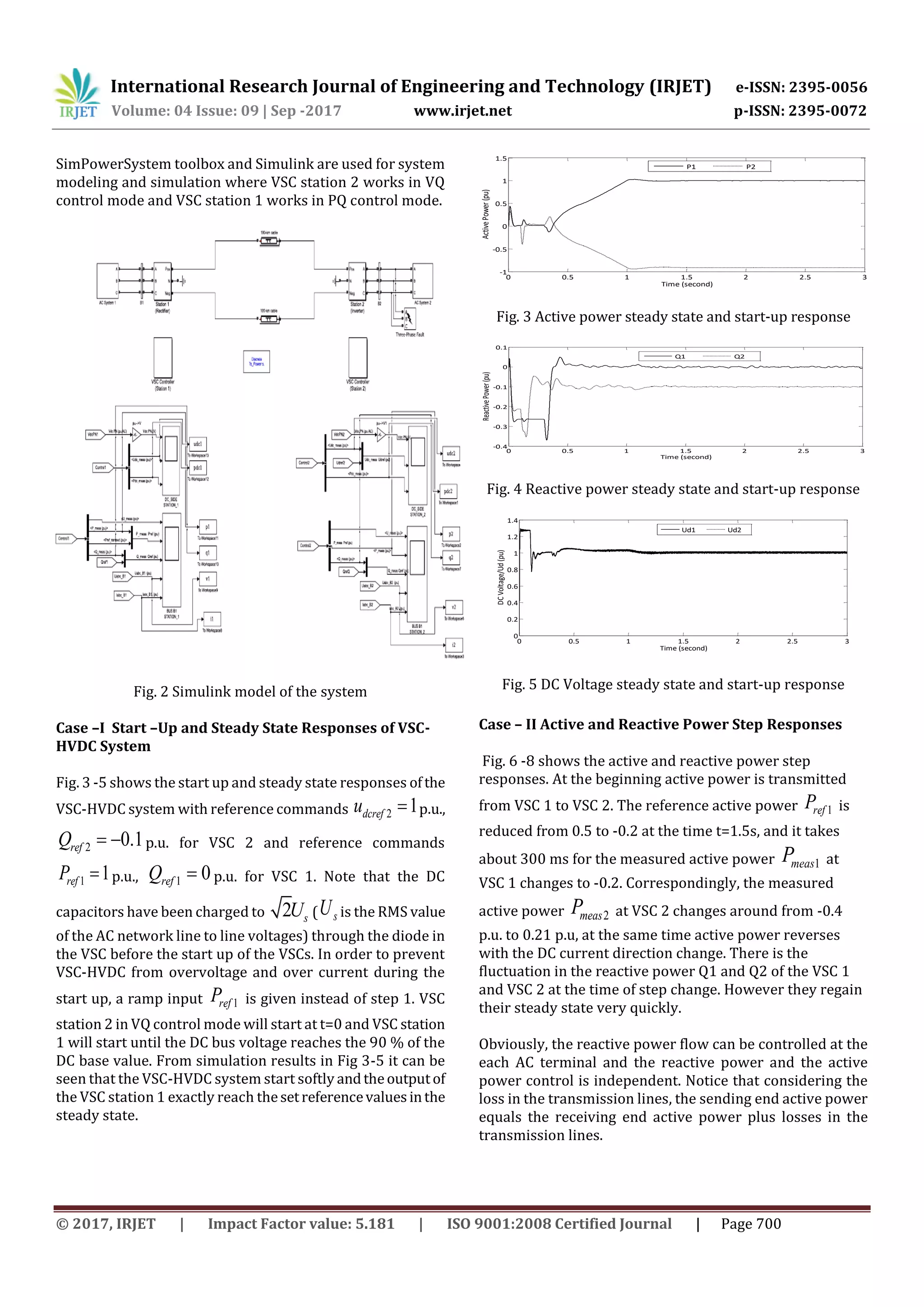
To evaluate the effectiveness of the proposed control
scheme, casesofTwo-Terminal IGBTVSC-HVDCisdeveloped
in MATLAB. The power system simulator or](https://image.slidesharecdn.com/irjet-v4i9121-171004090230/75/Steady-State-Fault-Analysis-of-VSC-HVDC-Transmission-System-2-2048.jpg)
![International Research Journal of Engineering and Technology (IRJET) e-ISSN: 2395-0056
Volume: 04 Issue: 09 | Sep -2017 www.irjet.net p-ISSN: 2395-0072
© 2017, IRJET | Impact Factor value: 5.181 | ISO 9001:2008 Certified Journal | Page 702
0 0.5 1 1.5 2 2.5 3
-1.5
-1
-0.5
0
0.5
1
1.5
Time (second)
ActivePower(pu)
P1 P2
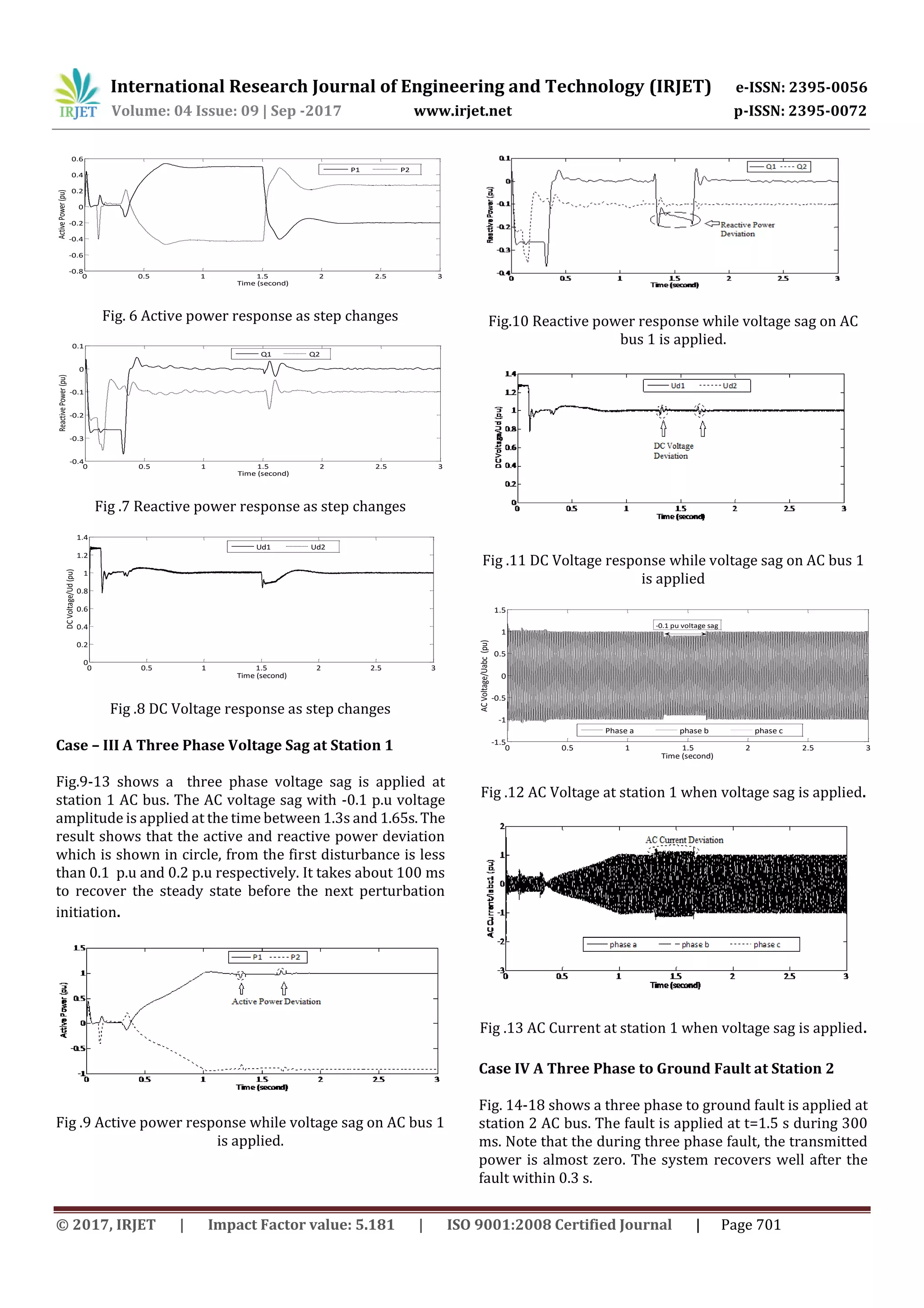
Fig .14 Active power response when three phase to ground
fault applied at station 2
0 0.5 1 1.5 2 2.5 3
-1.5
-1
-0.5
0
0.5
Time (second)
ReactivePower(pu)
Q1 Q2
Fig .15 Reactive power response when three phase to
ground fault applied at station 2
0 0.5 1 1.5 2 2.5 3
0
0.2
0.4
0.6
0.8
1
1.2
1.4
Time (second)
DCVoltage/Ud(pu)
Ud1 Ud2
Fig .16 DC Voltage response when three phase to ground
fault applied at station 2
0 0.5 1 1.5 2 2.5 3
-1.5
-1
-0.5
0
0.5
1
1.5
Time (second)
ACVoltage/Uabc2(pu)
phase a phase b phase c
Three phase to ground fault
Fig .17 AC Voltage when three phase to ground fault
applied at station 2.
0 0.5 1 1.5 2 2.5 3
-3
-2
-1
0
1
2
3
4
Time (second)
ACCurrent/Iabc2(pu)
phase a phase b phase c
Fig .18 AC Current when three phase to ground fault
applied at station 2.
5. CONCLUSIONS
(1) A steady state analysis of a VSC based HVDC system is
derived, starting from the basicmathematical equations.The
model consists of AC side equations, DC side equations and
converter (AC-DC coupling) equations. Also the control
systems are included in the model.
(2) The DC side equations have been generalized to multi-
terminal HVDC systems for the topology, proposing a
meshed DC system with every terminal consisting of one
converter and with the possibility of connections within the
DC system.
(3) Every terminal of the two-terminal HVDC system is
defined on the type of station. The control parameters are
tuned according to some predefined properties of the
dynamic responses. Therefore, a linear control model is
derived.
(4) The simulation results illustratethefast systemresponse
and the influence of a change in the control references on
different system variables.
(5) This thesis deals with the application of VSC-HVDC
transmission for the improvementofpowersystemstability.
Simulation result reveals that faster, independent control of
real and reactive power can greatly improve the stability of
power system.
(6) Some application of VSC-HVDC like interconnection of
asynchronous grids and benefits like black start capability,
frequency support, and voltage regulation can be achieved.
Voltage stability was improved and protect the system from
voltage collapsing due to lake of reactive power.
REFERENCES
[1] Omar A. Urquidez, Le Xie , “ Singular Value
Sensitivity Based Optimal Control ofEmbeddedVSC
– HVDC for Steady –State Voltage Stability
Enhancement”, IEEE Transactions on Power
System,Vol. 31,No. 1, January 2016.
[2] Krishna Chaitanya Diggavi, K. Janardan Rao , “
Performance Analysis of VSC – MMC Based Hybrid
HVDC Transmission System” IEEE International
Conference on Advances in Electrical , Electronics ,](https://image.slidesharecdn.com/irjet-v4i9121-171004090230/75/Steady-State-Fault-Analysis-of-VSC-HVDC-Transmission-System-5-2048.jpg)
![International Research Journal of Engineering and Technology (IRJET) e-ISSN: 2395-0056
Volume: 04 Issue: 09 | Sep -2017 www.irjet.net p-ISSN: 2395-0072
© 2017, IRJET | Impact Factor value: 5.181 | ISO 9001:2008 Certified Journal | Page 703
Information , Communication and Bio- Informatics
(AEEICB16) , 2016 .
[3] G.P. Adam, O. Anaya – Lara and G. Burt , “ Steady
State and Transient Performance of DC
Transmission Systems Based on HVDCTechnology”
Stratchlyde University , Institute of Energy and
Environment , Glasgow , U.K.
[4] K. Karthi ,R. Radhakrishnan ,JM. Bhaskaran ,Louis
Sam Titus , “Performance analysis on Various
Controllers of VSC – HVDC Transmission Systems” ,
IEEE International Conference on Computational
Intelligence and Computing Research ,2016
[5] Jiuping Pan, Reynaldo Nuqui, Kailash Srivastava,
Tomas Jonsson, Per Holmberg, Ying-Jiang Hafner , “
AC Grid with Embedded VSC – HVDC for Secure and
Efficient Power Delivery” , IEEE Energy 2030
Atlanta , GA USA , 17 – 18 November , 2008 .
[6] Guangkai Li , Member IEEE , “Stability Analysis of
the Initial Period of Power System Restoration
Using the Path Including VSC – HVDC” , Dept. of
Direct Current Transmission CSG Technology
Research Center Guangzhou , China .
[7] H. F. Latorre and M. Gandhari ,Member IEEE , “
Improvement of Voltage Stability by Using VSC –
HVDC” , IEEE T & D ASIA - SIEF 2009 , SEOUL ,
KOREA , OCTOBER 26 – 30 , 2009.
[8] Chengyong Zhao and Chunyi Guo , Member IEEE , “
Complete – Independent Control Stratgy of Active
and Reactive power for VSC Based HVDC System”,
National Science Foundation of China and North
China Electric Power University, IEEE Conference,
2009.
[9] Djehaf M , Zidi S – A , Khatir M , Hadjeri S , Djilani
Kobibi Y , “ Steady State and Dynamic Modeling of
Asynchronous Back-To – Back High Voltage Direct
Current Link With Voltage Source Converters" .
Conference IEEE , 2013](https://image.slidesharecdn.com/irjet-v4i9121-171004090230/75/Steady-State-Fault-Analysis-of-VSC-HVDC-Transmission-System-6-2048.jpg)

This document summarizes research on modeling and analyzing steady state faults in a voltage source converter (VSC) high voltage direct current (HVDC) transmission system. It presents the following: 1) A dynamic model of a VSC-HVDC back-to-back system is developed including VSC converters, AC and DC filters, and cables. Vector control is used to independently control active and reactive power. 2) Simulation cases demonstrate startup and steady state response, as well as the system's ability to independently control active and reactive power through step changes. 3) Additional cases show the system maintains stability under a voltage sag at one station and a three-phase fault at the other station, recovering quickly