Downloaded 168 times

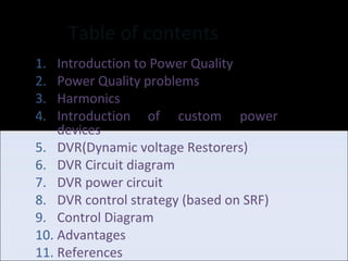

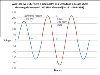
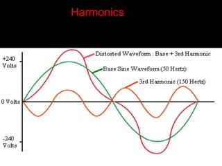
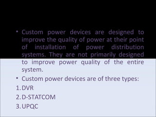
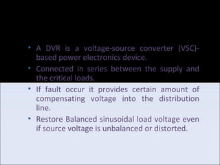
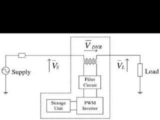
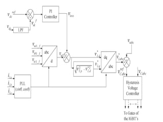


This document presents a voltage harmonic mitigation project using a DVR (Dynamic Voltage Restorer) based on MATLAB/Simulink. It was presented by 4 students under the supervision of Mr. Priyank Agarwal. The document introduces power quality issues such as voltage sags, swells and harmonics. It then discusses custom power devices for mitigating these issues including DVRs. It provides details on the DVR circuit diagram, power circuit and control strategy based on synchronous reference frame theory. The control strategy aims to restore balanced sinusoidal load voltage even during supply disturbances. MATLAB is used to model and simulate the DVR system.