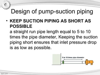
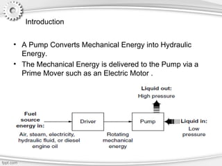
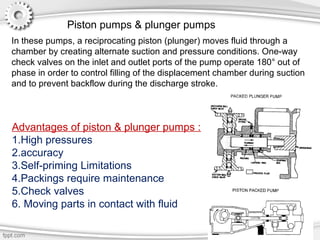
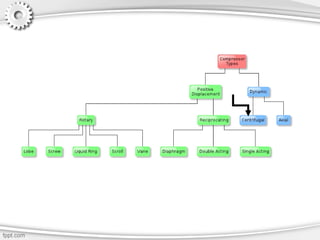
This document provides an overview of different types of mechanical pumps, including:
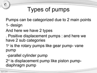
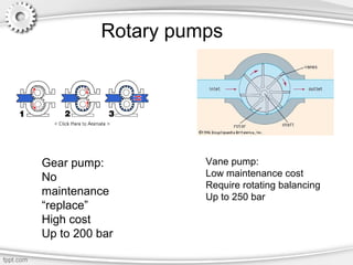
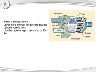
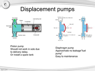
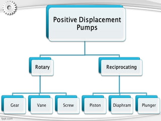
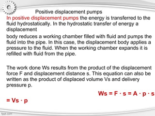
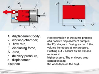
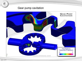
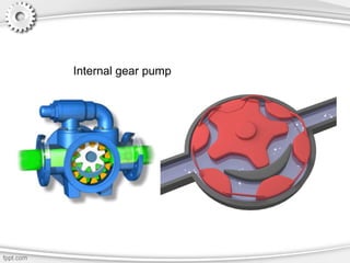
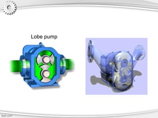
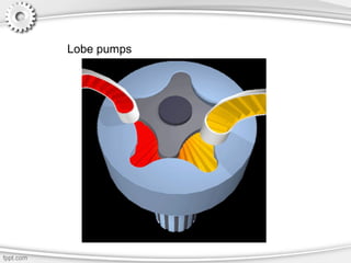
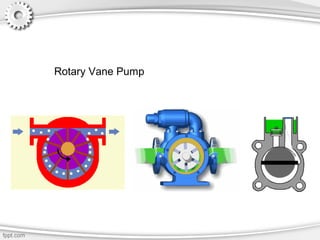
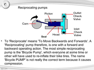
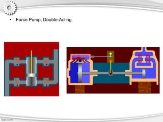
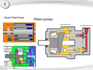
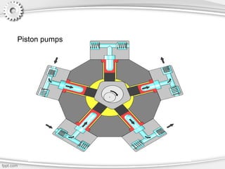
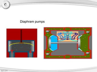
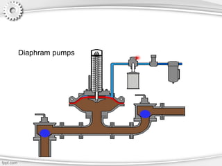
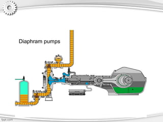
- Positive displacement pumps like gear pumps, vane pumps, piston pumps, and diaphragm pumps.
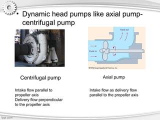
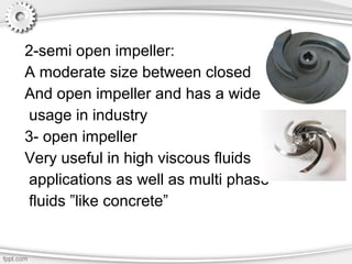
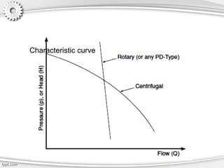
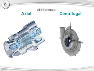
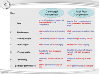
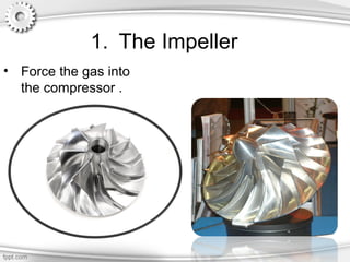
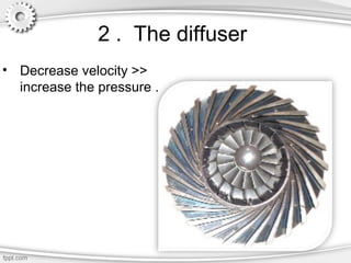
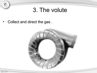
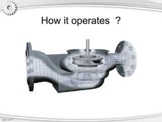
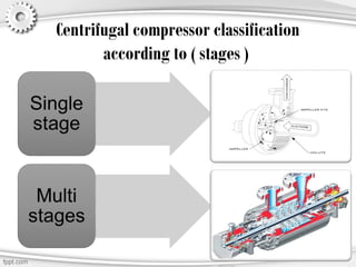
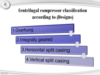
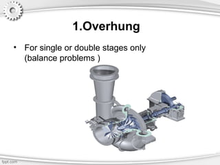
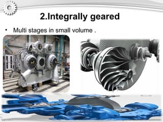
- Dynamic pumps like centrifugal pumps and axial pumps.
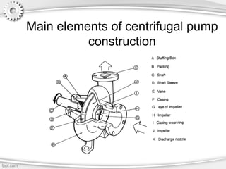
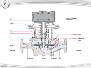
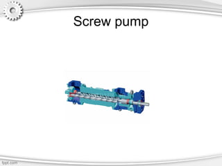
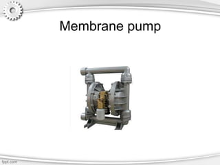
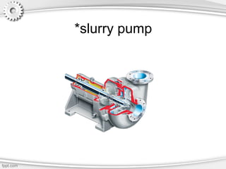
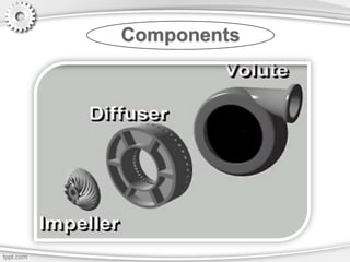
- Details are given on pump components, design considerations for suction piping, and characteristics of specific pump types like centrifugal pumps, screw pumps, and membrane pumps.


![2938 [autosaved]](https://cdn.slidesharecdn.com/ss_thumbnails/2938autosaved-141224115226-conversion-gate02-thumbnail.jpg?width=640&height=640&fit=bounds)


