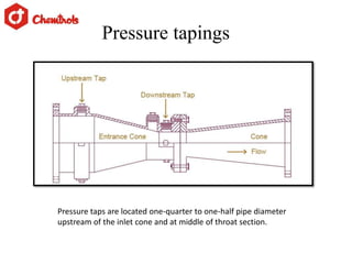
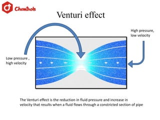
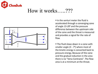
Venturi Tube
………lets measure flow by constriction
Compiled by
Mr. Harshal Revandkar
(harshal.revandkar@chemtrols.com)
Engineer (Metering and Measurement)
Chemtrols Industries Ltd.
Under the guidance of
Mr. R. C. Ramchandran
Manager (Flow Elements)
Chemtrols Samil (I) Pvt Ltd.
Principles of Fluid Flow in Pipes
laminar flow : the fluid travels as parallel layers
(known as streamlines).
Turbulent flow: The fluid does not travel in
parallel layers, but moves in a haphazard
manner
NR < 2000 – laminar flow
NR > 4000 – Turbulent flow
2000 < NR < 4000 – transition region
Why do we measure flow ????
Control
Billing
Alarm and indication
Techniques used in flow measurement
Variable area
Magnetic
Vortex
Pressure difference
Ultrasonic
Principle of pressure difference method
Pressure difference type flow elements
Orifice plate
Flow nozzle
Venturi tube
Venturi effect
The Venturi effect is the reduction in fluid pressure and increase in
velocity that results when a fluid flows through a constricted section of pipe
Low pressure ,
high velocity
High pressure,
low velocity
Working principle
Volumetric Flow measurement
 In the venturi meter the fluid is
accelerated through a converging cone
of angle 15-20o and the pressure
difference between the upstream side
of the cone and the throat is measured
and provides a signal for the rate of
flow.
 The fluid slows down in a cone with
smaller angle (5 - 7o) where most of
the kinetic energy is converted back to
pressure energy. Because of the cone
and the gradual reduction in the area
there is no "Vena Contracta". The flow
area is at a minimum at the throat.
How it works…..???
Installation and connection
Flanged Connection
Weld end Connection
Clamp connection
Flanged Installation
Flange Assembly
It consist of
Gasket
Stud and nuts
Weld ends
The buttwelding ends are prepared
by beveling each end of the venturi
to match a similar bevel on the pipe.
The two ends are then butted to the
pipeline and joined with a full
penetration weld.
The socket welding ends are prepared by
boring in each end of the venturi a
socket with an inside diameter slightly
larger than the pipe outside diameter.
The pipe slips into the socket where it
butts against a shoulder and then joins to
the valve with a fillet weld.
In this connection type,
slide draw band clamps
completely onto the inlet.
Slip-Connection
Pressure taps are located one-quarter to one-half pipe diameter
upstream of the inlet cone and at middle of throat section.
Pressure tapings
Factors need to be consider while design
1. Pipe Internal Diameter
2. Coefficient of thermal expansion for pipe and orifice
3. Meter range
4. Normal flow
5. Density (operating , NTP)
6. Viscosity
7. Differential pressure
8. Specific heat ratio
9. Operating pressure
10. Operating temperature
11. Pipe ID at operating temperature
12. Distance of tap
13. Reynolds number
Advantages Of Venturi tubes
They can handle large flow volumes at low
pressure drops.
They can be mounted in large diameter pipes
via flanged, welded or threaded-end fittings.
They can be used with nearly all liquids, as
well as those containing extreme solids
content.
Venturi tubes involve no projections into the
fluid and no sharp corners
 Also there are no rapid changes in contour.
Limitations
Bulky, especially in the larger sizes.
Primary cost for installation and usage of
venturi tubes proves to be very high
 Also there can be trouble in installation
and inspection of venturis.
What we offer to our clients…
1. Design Standards : ISO 5167-4, ASME MFC-3M
2. Sizes : DN 50 - 250 according to ISO 5167, 2” – 10”
according to ASME, other sizes on request.
3. Beta (d/D): 0,4 ≤ β ≤ 0,75
4. Pressure rating : PN 10-640, 150-2500 lbs, ISO PN
20-420.
5. Material : Carbon steel, AISI 316, Duplex, 254 SMO
others on request.
6. Mounting style : Weld ends according to DIN 2559 or
ANSI B16.25.
7. Pressure taps : Weld ends Ø 21.3 mm, 26.9 mm,
flanged.
8. Tapings : Single pressure tappings. Outlet cone : 7 –
15 ° .
Targeted Clients
Water suppliers
Petrochemical industries
Oil industries
Natural gas industries
LPG suppliers
Refineries
Power industries
Our highly reputed clients
And many more…..
Chemtrols Industries Ltd

Venturi

  • 1.
  • 2.
    Compiled by Mr. HarshalRevandkar (harshal.revandkar@chemtrols.com) Engineer (Metering and Measurement) Chemtrols Industries Ltd. Under the guidance of Mr. R. C. Ramchandran Manager (Flow Elements) Chemtrols Samil (I) Pvt Ltd.
  • 3.
    Principles of FluidFlow in Pipes laminar flow : the fluid travels as parallel layers (known as streamlines). Turbulent flow: The fluid does not travel in parallel layers, but moves in a haphazard manner NR < 2000 – laminar flow NR > 4000 – Turbulent flow 2000 < NR < 4000 – transition region
  • 4.
    Why do wemeasure flow ???? Control Billing Alarm and indication
  • 5.
    Techniques used inflow measurement Variable area Magnetic Vortex Pressure difference Ultrasonic
  • 6.
    Principle of pressuredifference method
  • 7.
    Pressure difference typeflow elements Orifice plate Flow nozzle Venturi tube
  • 8.
    Venturi effect The Venturieffect is the reduction in fluid pressure and increase in velocity that results when a fluid flows through a constricted section of pipe Low pressure , high velocity High pressure, low velocity
  • 9.
  • 10.
     In theventuri meter the fluid is accelerated through a converging cone of angle 15-20o and the pressure difference between the upstream side of the cone and the throat is measured and provides a signal for the rate of flow.  The fluid slows down in a cone with smaller angle (5 - 7o) where most of the kinetic energy is converted back to pressure energy. Because of the cone and the gradual reduction in the area there is no "Vena Contracta". The flow area is at a minimum at the throat. How it works…..???
  • 11.
    Installation and connection FlangedConnection Weld end Connection Clamp connection
  • 12.
  • 13.
    Flange Assembly It consistof Gasket Stud and nuts
  • 14.
    Weld ends The buttweldingends are prepared by beveling each end of the venturi to match a similar bevel on the pipe. The two ends are then butted to the pipeline and joined with a full penetration weld. The socket welding ends are prepared by boring in each end of the venturi a socket with an inside diameter slightly larger than the pipe outside diameter. The pipe slips into the socket where it butts against a shoulder and then joins to the valve with a fillet weld.
  • 15.
    In this connectiontype, slide draw band clamps completely onto the inlet. Slip-Connection
  • 16.
    Pressure taps arelocated one-quarter to one-half pipe diameter upstream of the inlet cone and at middle of throat section. Pressure tapings
  • 17.
    Factors need tobe consider while design 1. Pipe Internal Diameter 2. Coefficient of thermal expansion for pipe and orifice 3. Meter range 4. Normal flow 5. Density (operating , NTP) 6. Viscosity 7. Differential pressure 8. Specific heat ratio 9. Operating pressure 10. Operating temperature 11. Pipe ID at operating temperature 12. Distance of tap 13. Reynolds number
  • 18.
    Advantages Of Venturitubes They can handle large flow volumes at low pressure drops. They can be mounted in large diameter pipes via flanged, welded or threaded-end fittings. They can be used with nearly all liquids, as well as those containing extreme solids content. Venturi tubes involve no projections into the fluid and no sharp corners  Also there are no rapid changes in contour.
  • 19.
    Limitations Bulky, especially inthe larger sizes. Primary cost for installation and usage of venturi tubes proves to be very high  Also there can be trouble in installation and inspection of venturis.
  • 20.
    What we offerto our clients… 1. Design Standards : ISO 5167-4, ASME MFC-3M 2. Sizes : DN 50 - 250 according to ISO 5167, 2” – 10” according to ASME, other sizes on request. 3. Beta (d/D): 0,4 ≤ β ≤ 0,75 4. Pressure rating : PN 10-640, 150-2500 lbs, ISO PN 20-420. 5. Material : Carbon steel, AISI 316, Duplex, 254 SMO others on request. 6. Mounting style : Weld ends according to DIN 2559 or ANSI B16.25. 7. Pressure taps : Weld ends Ø 21.3 mm, 26.9 mm, flanged. 8. Tapings : Single pressure tappings. Outlet cone : 7 – 15 ° .
  • 21.
    Targeted Clients Water suppliers Petrochemicalindustries Oil industries Natural gas industries LPG suppliers Refineries Power industries
  • 22.
    Our highly reputedclients And many more…..
  • 23.