Downloaded 44 times


![10
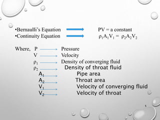
g(Z1-Z2)+1/2(V12+V22)=(P2-P1)/ρ
Energy equation (horizontal arrangement)
If Z1=Z2
½(v12-v22)= (P2-P1)/ρ ----- (1)
As per law at continuity
A1V1=A2V2 (since density is constant)
V1=(A2/A1)V2 & V2=(A1/A2)V1
Sub V1 value in (1)
½[(A2/A1)*V22-V22]=∆P/ρ
V22=(A1
2/A2
2-A1
2) * 2∆P/ρ](https://image.slidesharecdn.com/venturimeter-170505180441/85/Venturi-meter-10-320.jpg)

![12
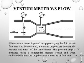
Q2=Cd . E . M . A2 √2g{hm[(wm/w )-1]-(Zx-Zy)}
Q2=Cd.E.M.A2√2g {hm(sg-1)-(Zx-Zy)}
Q2 in terms of specific weight
Q2 in terms of specific gravity](https://image.slidesharecdn.com/venturimeter-170505180441/85/Venturi-meter-12-320.jpg)


![20
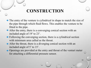
SAMPLE PROBLEM
A horizontal venture meter with 15 cm inlet . 7.5 cm throat is
used for measurement of flow of water .The differential pressure
between inlet and throat is 17.5 cm, when measured using U-
TUBE manometer. Make the calculations for the water flow rate
where Cd for venturi is 0.97. Specific gravity =13.6.
Q2= Cd . E . M . A2 √2g{ hm [(ρm/ρ )-1]}
M=A1/√A12-A22
A1=π*d2/4=π*152/4=176.71 ,
A2=π*d2/4=π*7.52/4=44.178
M= 1.03
Q2=0.97
* 1
* 1.03
*44.178√2
*9.8
*17.5(13.6-1)
=0.02901 m3/sec
Sol
:](https://image.slidesharecdn.com/venturimeter-170505180441/85/Venturi-meter-20-320.jpg)


The document provides a detailed overview of a venturi meter, a device used to measure the flow rate of fluids in pipes, consisting of three main parts: a converging section, a throat, and a diverging section. It discusses the working principle based on Bernoulli's and the continuity equations, types of venturimeters, as well as applications, advantages, and disadvantages. Additionally, it includes information on the construction, operation, and calculations for measuring flow, using a manometer for pressure differential measurements.