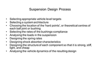
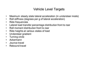
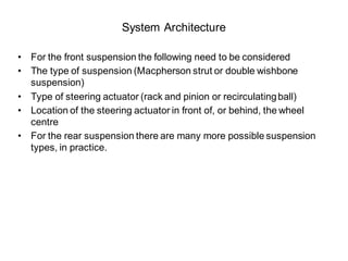
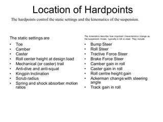
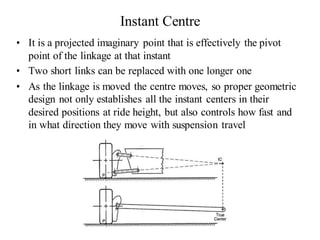
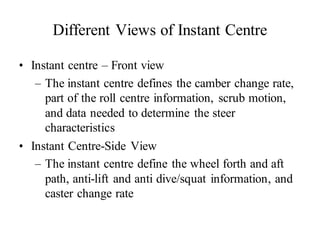
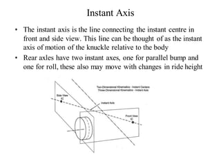
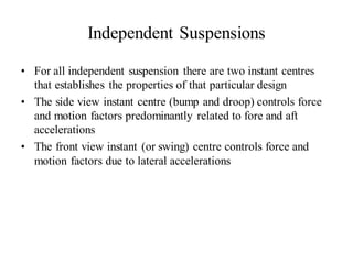
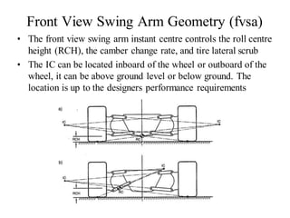
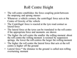
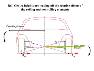
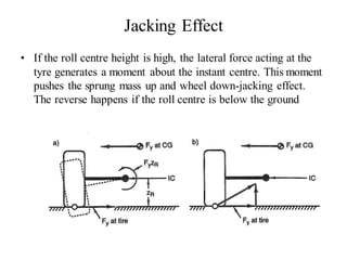
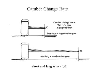
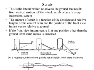
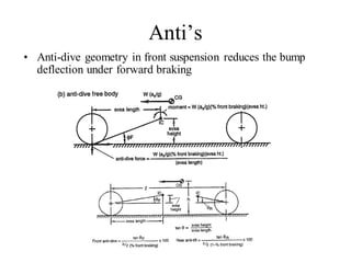
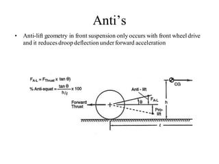
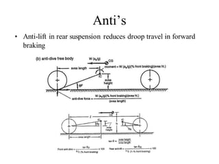
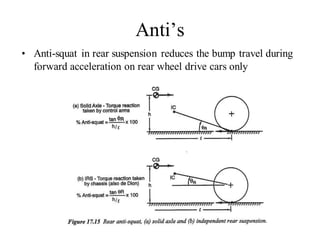
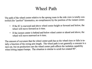
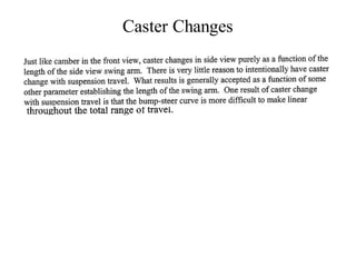
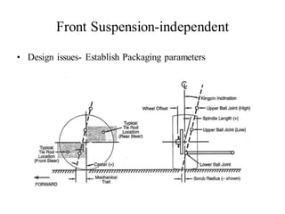
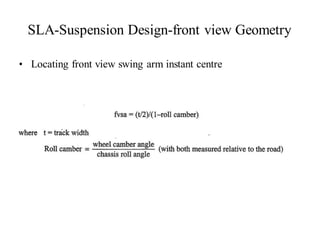
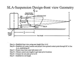
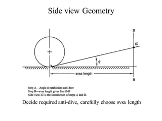
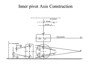
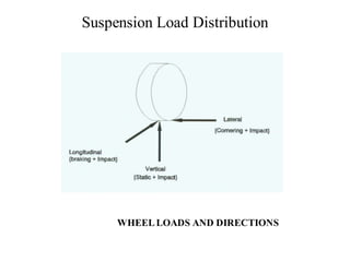
The document provides an overview of the suspension design process, including selecting vehicle targets, choosing a system architecture, locating hard points, analyzing loads, and designing individual components. Key aspects discussed are vehicle level targets, types of front and rear suspension architectures, the role of instant centers and axes in controlling suspension kinematics, methods for analyzing load distribution, and factors considered in the design of independent front and rear beam-type suspensions.
![Suspension Load Distribution
• Front Axle Braking per wheel:
FB =
[static+ dynamic
2
load]
=
[W
2
bcg
l
+ ma
hcg
]
l
=
W[
2
bcg
+
a
l g
hcg
]
l
= tire-road coefficient of friction W = total vehicle weight
bcg = Cg-to-rear axledistance (LR) l = wheelbase length
a = ave. longitudinal acceleration (deceleration) m = vehicle mass
hcg = Cg height g = acceleration of gravity](https://image.slidesharecdn.com/vdhs-11-suspensiondesign-220524000224-55604b52/85/VDHS-11-Suspension-Design-docx-42-320.jpg)
![Suspension Load Distribution
• VERTICAL: (Total is commonly considered as a 3 g load)
V =
3
[W
2
bcg
l
+ ma
hcg
]
l
=
3
W[
2
bcg g +a
gl
hcg
]](https://image.slidesharecdn.com/vdhs-11-suspensiondesign-220524000224-55604b52/85/VDHS-11-Suspension-Design-docx-43-320.jpg)
![Suspension Load Distribution
• LATERAL: (commonly considered as a 2 g load)
FL =W[
bcg g +a
gl
hcg
]](https://image.slidesharecdn.com/vdhs-11-suspensiondesign-220524000224-55604b52/85/VDHS-11-Suspension-Design-docx-44-320.jpg)
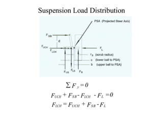
![Suspension Load Distribution
Side view front wheel SLA front suspension
LB is lower ball joint
M LB =0 Fus h= FB a
a
Fus = FB
h
Fx =0 FUS - FLS + FB = 0
F LS = FUS + FB FLS = FB [
a
+1]
h](https://image.slidesharecdn.com/vdhs-11-suspensiondesign-220524000224-55604b52/85/VDHS-11-Suspension-Design-docx-45-320.jpg)
![Suspension Load Distribution
SLA front SUSPENSION TOPVIEW
M PSA= 0
FSB d + FUS b - FLS c - Fb rs = 0
1 Fb a
FSB =
d
[ FLS c+ Fb rs - FUS b] =
d
[ rs + c - (b -c)]
h](https://image.slidesharecdn.com/vdhs-11-suspensiondesign-220524000224-55604b52/85/VDHS-11-Suspension-Design-docx-46-320.jpg)
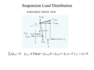
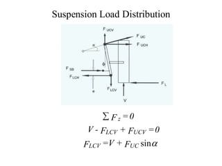
![Suspension Load Distribution
FUCV = FUC sin FUCH = FUC sin
F =
V( rs +c)- FSB e - FL a
UC
sin
= FB
tan +cos h
a
FLCH
d
[( rs +c)-
(b - c)]+ FUC cos
h
- FL](https://image.slidesharecdn.com/vdhs-11-suspensiondesign-220524000224-55604b52/85/VDHS-11-Suspension-Design-docx-49-320.jpg)