Today, we have to consider different demands to make a successful and reliable concept design of modern suspension systems. Beside package and lightweight construction especially the real scopes of a suspension system, kinematics and compliances are getting more and more important to fulfill all the technical needs coming from the automotive market. In particular, the development of suspension system for sport utility vehicle (SUVs) has to satisfy various demands and strong characteristic criteria coming from the on-road and off-road driving conditions.
In this paper, the main kinematics and compliance effects for an independent SUV suspension system will be explained and illustrated:
Explanation of different load cases coming from the individual purpose of a sport utility vehicle (off road & on road)
- Illustration of the K&C influences coming from the use of active systems to control roll and pitch angles or the individual wheel loads
- Development of an analytic approach to solve the kinematic and compliance needs.
- Simulation description and results to verify the suspension design.
- Analysis of vibration problems resulting from suspension concepts.
A Four wheel steering system also known as Quadra steering system. In this paper, both front
wheel and rear wheels can be steered according to speed other vehicle and space available for
turning. Quadra steer gives full size vehicle greater ease while driving at low speed, improves
stability, handling and control at higher speed.
Production-built cars tend to under steer or, in few instances, overseer. If a car could
automatically compensate for an under steer overseer problem, the driver would enjoy nearly
neutral steering under varying conditions. Four wheel systems is a serious effort on the part of
automotive design engineers to provide near-neutral steering.
This system finds application in off-highway vehicles such as forklifts, agricultural and
construction equipment mining machinery also in Heavy Motor Vehicles. It is also useful in
passenger cars.
It improves handling and helps the vehicle make tighter turns. This system is used to minimize
the turning radius.
Four Wheel Active Steering / Without VideosGoodarz Mehr
This presentation gives you more information about Four Wheel Steering systems, physical means to incorporate them and control methods used to determine rear steering angles. In the end, results of our various simulations using CarSim vehicle simulation software and MATLAB Simulink are presented.
IJRET : International Journal of Research in Engineering and Technology is an international peer reviewed, online journal published by eSAT Publishing House for the enhancement of research in various disciplines of Engineering and Technology. The aim and scope of the journal is to provide an academic medium and an important reference for the advancement and dissemination of research results that support high-level learning, teaching and research in the fields of Engineering and Technology. We bring together Scientists, Academician, Field Engineers, Scholars and Students of related fields of Engineering and Technology
Forces are generated at the tire contact patch during various maneuvers of the car and transferred to the chassis through the suspension links. Calculating the forces on every link is important to design the suspension system as all the forces from wheel to the chassis are transferred by the suspension linkages. These forces have been calculated for all the links of a double wishbone suspension geometry. The load paths and FBD have been drawn and axial stress in the all the linkages
Comparison Of Multibody Dynamic Analysis Of Double Wishbone Suspension Using ...IJRES Journal
This paper presents the multibody dynamic analysis of wishbone suspension for automotive cars. Modeling and analysis of suspension is carried out using MATLAB SimMechanics toolbox. Rigid dynamic analysis of suspension is also carried out using ANSYS software. Results of both the analysis are compared and it is observed that results of both the analysis are similar.
Design and Analysis of Side Force Spring in McPherson Strut - PHASE 1tulasiva
To reduce the magnitude of lateral forces generated by cornering of vehicle on dampers due to buckling action which is caused by packaging issues occurred during the assembly of McPherson strut suspension system in passenger vehicle.
In order to achieve our desired results, the piercing points axis must reach as close with line of forces (Kingpin axis).
The International Journal of Engineering and Science (The IJES)theijes
The International Journal of Engineering & Science is aimed at providing a platform for researchers, engineers, scientists, or educators to publish their original research results, to exchange new ideas, to disseminate information in innovative designs, engineering experiences and technological skills. It is also the Journal's objective to promote engineering and technology education. All papers submitted to the Journal will be blind peer-reviewed. Only original articles will be published.
Different Modes in Four Wheel Steered Multi-Utility Vehiclesresearchinventy
Four wheel steering is the innovative technology in which research is going on. The front-to-rear wheel alignment plays a significant role in the directional stability of a vehicle in a good manner. Four wheel steering is the system that allows the rear wheels to turn for maneuvering, rather than just follow the front wheels. The system is employed by some vehicles to improve steering response, increase vehicle stability while maneuvering at high speed, or to decrease turning radius at low speed. In Four Wheel Steering System, the rear wheels do play an active role for steering, which can be guided at high as well as in low speeds. In this paper we made a four wheel steered vehicle for the analysis of four wheel steering systems (4WS). Apart from normal front wheel steered vehicle our designed model can work in all four modes of four wheel steering. The four modes include front wheel steering, 360 degree rotation of vehicle with in the position, parallel parking mode and shorter radius mode. 4WS is one of the devices which are used for the improvement of vehicle maneuverability and stability. Another significant finding is the effect of vehicle add-ons which showed how a multi utility vehicle can be made by giving a floor cleaning machine with it. We introduced Neodymium magnets to attract metal scraps, which helps us to clean the floor. It is expected that our different modes will be very beneficial to everyone who involved or interested in the automotive design, steering modes, analysis, performance assessment and applications of various types of four wheel steering systems.
Suspension system is the most significant part which heavily affects the vehicle handling performance and ride quality. Because of its structures limit, the passive suspension system can hardly improve the two properties at the same time. Since the advent of active suspension system, it has become the research hot spot. In this review paper we shall see the advantages of the active suspension system over the passive suspensions systems and its incorporation in passenger vehicles.
Selection P arameter of AVT suspension systemIRJEETJournal
The Suspension is the most vital sub-system in the automobile. its main function is to load transfer to the wheels and protection of the driver from the road shocks .The purpose of this paper is to select proper suspension system for front and rear of All Terrain vehicles (ATV) and to thereafter design, analyze, simulate and test the suspension system for optimum performance of the vehicle, driver safety and maximum driver comfort. The stability and road handling of vehicle is very important for parameters.
The system was designed to be durable enough to withstand with road shocks and vibration from harsh terrain where ATV generally used. The springs were designed by calculation and the components were designed using SOLID WORKS.
[ Video ]
منحة جزئية تصل الى 60%
رابط التسجيل: https://tinyurl.com/36p25tpt
🎓 📞للتواصل و الإستفسار:
📌 الأستاذ عمر عطية http://wa.link/99sy7u
البرامج الدراسية المتاحة للمنحة هي
1️⃣ بكالوريوس الادارة الاستراتيجية
2️⃣ كالوريوس ادارة المصارف الاسلامية
3️⃣ بكالوريوس الاذاعة و التلفاز
4️⃣ بكالوريوس تصميم أزياء
5️⃣ بكالوريوس تربية – منهج منتسوري
6️⃣ بكالوريوس الإدارة الصحية
7️⃣ بكالوريوس علم الفلسفة
8️⃣ بكالوريوس علم الاجتماع
9️⃣ بكالوريوس علاقات عامة
10 بكالوريوس في الخدمات اللوجستية والإمداد
Fatigue or Durability Analysis of Steering Knuckleijsrd.com
the purpose of the study of this thesis is to discuss analysis the acting force upon the steering knuckle while in track or random load for a vehicle. Steering knuckle is main important part in the vehicle because that requires lots of attention in selection because once it is damaged then it have to replace with the new one. Structural Components such as a steering knuckle might be strong enough to withstand a single applied load. But what happens when the part operates over and over, day after today? To predict component failure in such cases requires what's called fatigue or durability analysis. For our purposes, a constant or static load does not cause failure. What counts is the impact of working or fluctuating loads. Failures, or fractures, take place when cracks get so large that remaining material can no longer endure stresses and strains. In classic structural analyses, failure predictions are based solely on material strength or yield strength. Durability analysis goes beyond this, evaluating failure based on repeated simple or complex loading.
Factors Influencing the Technical Condition of Automobile Steering System and...IJRESJOURNAL
ABSTRACT: With the development of economy, human to the world to further explore and cognitive, people’s dependent on cars is becoming more and more obvious, The automobile steering technology system play an important role in the safety and performance of the improved control of the car. At first, this paper summarizes the automotive steering system the research status and development trend, followed by a summary of the automotive steering system development process, on the car steering law were briefly introduced. Finally, further analysis of the steering system is mainly technical condition detection technique
Study of fuel droplets from injector using ansysIRJEETJournal
The main objective of this study is to simulate the properties of fuel droplets inside the multihole nozzle fuel injector. A 3D solid model of multihole fuel injector is prepared using SOLIDWORKS and flow analysis (CFD) is done to check the flow properties of the fuel droplets inside the fuel injector. Variation of injection pressure on air-fuel mixer is studied in detail in this work.
Scope of this work deals with the improvement of internal combustion engine emissions and fuel economy performance by proper atomization of droplets into the cylinder.
We are using ANSYS computational fluid dynamics (CFD) software to study the multihole fuel injector to deliver droplets in just the right spray pattern to optimize engine performance.
An ATV roll cage is a specially designed protective frame around the driver that protects the driver in each & every condition. During the designing of roll cage take few objectives like diver safety, easy of manufacturing, light weight, ergonomics. This paper outline dynamic analysis of roll cage of ATV by doing per & post processing in ANSYS 18.2 & CAD modelling done in solid works 2018 to obtain optimum FOS (factor of safety) in worst condition under a set of particular rules given by Society of Automotive Engineers (SAE) Which ensure that the roll cage of ATV will be safe in all conditions.
Validation and Designing of Intake System for 1 Cylinder SI Engine in Formula...IRJEETJournal
The concept is to design an intake system for Formula Student race car using KTM RC 390 engine. The main objectives taken under consideration for the design are to minimize the restriction to flow, use of tuned pressure wave to increase the charge intake and the optimization of flow rate.
Flow optimization is done on some assumption and taking gas dynamics of the system in consideration. This work support the initial calculation parameters to start the designing and manufacturing of intake system. The length of runner plays important form in delivering the amount of air in the cylinder chamber. Large runner length is good at low speeds (filling losses at higher speeds) and small runner intake systems are good for higher speeds.
CFD Simulation of Thermo Acoustic CoolingIRJEETJournal
Thermo-acoustic Refrigerators use acoustic power for generating cold temperatures. Development of refrigerators based on thermos-acoustic technology is a novel solution to the present day need of cooling, without causing environmental hazards. With added advantages like minimal moving parts and absence of CFC refrigerants, these devices can attain very low temperatures maintaining a compact size. The present work describes an in-depth theoretical analysis of standing wave thermos-acoustic refrigerators. This consists of detailed parametric studies, transient state analysis and a design using available simulation software. Design and construction of a thermos-acoustic refrigerator using a commercially available electro-dynamic motor is also presented.
Study of Renewable Energy Sources in India - A ReviewIRJEETJournal
Energy is at the heart of most critical economic, environmental and developmental issues facing the world today. Clean, efficient, affordable and reliable energy services are indispensable for global prosperity. India with a population of 1.2 billion people, is one of the largest and fastest growing economies in the world. There is always a very strong demand for energy, which currently comes mainly from coal, oil and other sources which are non-renewable. Also, the consumption of these energies is harmful for the environment.
This means that “India has to switch from non-renewable energy (oil and coal) to renewable energy or find some alternative options for energy sources”. The Indian government has already taken several steps and launched various agencies and platforms to achieve its goal of becoming one of the world's leading producers of clean energy. Renewable energy is the energy of a resource that can be replaced by existing energy sources such as solar, wind, water, biological processes and geothermal heat fluxes. These energy resources can be used directly or indirectly as forms of energy. In this paper we will discuss the potential areas and technological opportunities in this direction in the context of India.
Production of diesel like fuel from waste engine oil and engine performance t...IRJEETJournal
Engine oil has become a very useful and versatile material with a wide range of application. In the past 60 years, the automotive and industry sector is developing on a large scale and there productivity is raising up exponentially. Parallel to the growth of these sectors the demand of engine oil and high viscous lubricants are increasing which leads to the problem of pollution worldwide due to its slow decomposing behavior and toxic impacts on environment.
Researches are going on to recycle the waste engine oil and produce diesel like fuels with different processes. This Research covers the production of diesel like fuel from waste engine oil by doing pyrolysis and testing it in CI engine to check and compare the engine performance.
It is also seen that from 1 kg of waste high density engine oil, about 750ml of fuel can be produced. And, the produced fuel can be used for domestic purpose, in automotive field, and in industries also. This fuel produced by pyrolysis of waste engine oil is suitable to use in a diesel engine partially or completely.
Analysis of Disc Brake by Modifying in Design and Material Composition of DiscIRJEETJournal
Disc brake were most popular on sports cars when Disc brakes were first introduced, since these vehicles are more demanding about brake performance. Disc brakes are more common form in most passenger vehicles, although many (particularly light weight vehicles) use drum brakes on the rear wheels to keep costs and weight down as well as to simplify the provisions for a parking brake. As the front brakes required most of the braking effort, this can be a reasonable compromise. Many early implementations for automobiles located the brakes on the inboard side of the driveshaft, near the differential, while most brakes today are located inside the wheels. An inboard location reduces the unsparing weight and eliminates a source of heat transfer to the tires.
The presented work shows that there is wide region to be worked upon in the field of brake disc. By selecting cast iron as a rotor material creates problems for the designer. Problem stated as being overweight of grey cast iron disc. For same dimension of disc if disc of grey cast weights 7.5 kg, an aluminium disc will weight around 2.5 kg. Hence this work clearly shows that there is a weight difference between both the materials. Another problem that has been also been pointed of is corrosion, grey cast iron corrode in a humid environment. Hence the new material is proposed that is aluminium-silicon which is having property equivalent or more appropriate than grey cast iron.
Hence new material having high thermal conductivity than grey cast iron to reduce temperature induced stress. In present modelling and analyzing will be performing for two design of brake rotor i.e. solid and ventilated. New materials for brake pads to reduce the wear and increase stress handling capability.
Saudi Arabia stands as a titan in the global energy landscape, renowned for its abundant oil and gas resources. It's the largest exporter of petroleum and holds some of the world's most significant reserves. Let's delve into the top 10 oil and gas projects shaping Saudi Arabia's energy future in 2024.
Hybrid optimization of pumped hydro system and solar- Engr. Abdul-Azeez.pdffxintegritypublishin
Advancements in technology unveil a myriad of electrical and electronic breakthroughs geared towards efficiently harnessing limited resources to meet human energy demands. The optimization of hybrid solar PV panels and pumped hydro energy supply systems plays a pivotal role in utilizing natural resources effectively. This initiative not only benefits humanity but also fosters environmental sustainability. The study investigated the design optimization of these hybrid systems, focusing on understanding solar radiation patterns, identifying geographical influences on solar radiation, formulating a mathematical model for system optimization, and determining the optimal configuration of PV panels and pumped hydro storage. Through a comparative analysis approach and eight weeks of data collection, the study addressed key research questions related to solar radiation patterns and optimal system design. The findings highlighted regions with heightened solar radiation levels, showcasing substantial potential for power generation and emphasizing the system's efficiency. Optimizing system design significantly boosted power generation, promoted renewable energy utilization, and enhanced energy storage capacity. The study underscored the benefits of optimizing hybrid solar PV panels and pumped hydro energy supply systems for sustainable energy usage. Optimizing the design of solar PV panels and pumped hydro energy supply systems as examined across diverse climatic conditions in a developing country, not only enhances power generation but also improves the integration of renewable energy sources and boosts energy storage capacities, particularly beneficial for less economically prosperous regions. Additionally, the study provides valuable insights for advancing energy research in economically viable areas. Recommendations included conducting site-specific assessments, utilizing advanced modeling tools, implementing regular maintenance protocols, and enhancing communication among system components.
Overview of the fundamental roles in Hydropower generation and the components involved in wider Electrical Engineering.
This paper presents the design and construction of hydroelectric dams from the hydrologist’s survey of the valley before construction, all aspects and involved disciplines, fluid dynamics, structural engineering, generation and mains frequency regulation to the very transmission of power through the network in the United Kingdom.
Author: Robbie Edward Sayers
Collaborators and co editors: Charlie Sims and Connor Healey.
(C) 2024 Robbie E. Sayers
NO1 Uk best vashikaran specialist in delhi vashikaran baba near me online vas...Amil Baba Dawood bangali
Contact with Dawood Bhai Just call on +92322-6382012 and we'll help you. We'll solve all your problems within 12 to 24 hours and with 101% guarantee and with astrology systematic. If you want to take any personal or professional advice then also you can call us on +92322-6382012 , ONLINE LOVE PROBLEM & Other all types of Daily Life Problem's.Then CALL or WHATSAPP us on +92322-6382012 and Get all these problems solutions here by Amil Baba DAWOOD BANGALI
#vashikaranspecialist #astrologer #palmistry #amliyaat #taweez #manpasandshadi #horoscope #spiritual #lovelife #lovespell #marriagespell#aamilbabainpakistan #amilbabainkarachi #powerfullblackmagicspell #kalajadumantarspecialist #realamilbaba #AmilbabainPakistan #astrologerincanada #astrologerindubai #lovespellsmaster #kalajaduspecialist #lovespellsthatwork #aamilbabainlahore#blackmagicformarriage #aamilbaba #kalajadu #kalailam #taweez #wazifaexpert #jadumantar #vashikaranspecialist #astrologer #palmistry #amliyaat #taweez #manpasandshadi #horoscope #spiritual #lovelife #lovespell #marriagespell#aamilbabainpakistan #amilbabainkarachi #powerfullblackmagicspell #kalajadumantarspecialist #realamilbaba #AmilbabainPakistan #astrologerincanada #astrologerindubai #lovespellsmaster #kalajaduspecialist #lovespellsthatwork #aamilbabainlahore #blackmagicforlove #blackmagicformarriage #aamilbaba #kalajadu #kalailam #taweez #wazifaexpert #jadumantar #vashikaranspecialist #astrologer #palmistry #amliyaat #taweez #manpasandshadi #horoscope #spiritual #lovelife #lovespell #marriagespell#aamilbabainpakistan #amilbabainkarachi #powerfullblackmagicspell #kalajadumantarspecialist #realamilbaba #AmilbabainPakistan #astrologerincanada #astrologerindubai #lovespellsmaster #kalajaduspecialist #lovespellsthatwork #aamilbabainlahore #Amilbabainuk #amilbabainspain #amilbabaindubai #Amilbabainnorway #amilbabainkrachi #amilbabainlahore #amilbabaingujranwalan #amilbabainislamabad
Sachpazis:Terzaghi Bearing Capacity Estimation in simple terms with Calculati...Dr.Costas Sachpazis
Terzaghi's soil bearing capacity theory, developed by Karl Terzaghi, is a fundamental principle in geotechnical engineering used to determine the bearing capacity of shallow foundations. This theory provides a method to calculate the ultimate bearing capacity of soil, which is the maximum load per unit area that the soil can support without undergoing shear failure. The Calculation HTML Code included.
Explore the innovative world of trenchless pipe repair with our comprehensive guide, "The Benefits and Techniques of Trenchless Pipe Repair." This document delves into the modern methods of repairing underground pipes without the need for extensive excavation, highlighting the numerous advantages and the latest techniques used in the industry.
Learn about the cost savings, reduced environmental impact, and minimal disruption associated with trenchless technology. Discover detailed explanations of popular techniques such as pipe bursting, cured-in-place pipe (CIPP) lining, and directional drilling. Understand how these methods can be applied to various types of infrastructure, from residential plumbing to large-scale municipal systems.
Ideal for homeowners, contractors, engineers, and anyone interested in modern plumbing solutions, this guide provides valuable insights into why trenchless pipe repair is becoming the preferred choice for pipe rehabilitation. Stay informed about the latest advancements and best practices in the field.
Student information management system project report ii.pdfKamal Acharya
Our project explains about the student management. This project mainly explains the various actions related to student details. This project shows some ease in adding, editing and deleting the student details. It also provides a less time consuming process for viewing, adding, editing and deleting the marks of the students.
Student information management system project report ii.pdf
Kinematics and Compliance of Sports Utility Vehicle
1. International Research Journal in Engineering and Emerging Technology (IRJEET)
Volume – 01, Issue – 01 – 2020
www.we-irjeet.com 2020 IRJEET – All Right Reserved 1 | Page
Kinematics and Compliance of Sports Utility Vehicle
Sumit Jain1
, Kuldeep Sharma2
1
(Department of Mechanical Engineering / Jaipur Engineering College and Research Centre, India)
2
(Training & Placement officer, Professor / Jaipur Engineering College and Research Centre, India)
Abstract: Today, we have to consider different demands to make a successful and reliable concept design of
modern suspension systems. Beside package and lightweight construction especially the real scopes of a
suspension system, kinematics and compliances are getting more and more important to fulfill all the technical
needs coming from the automotive market. In particular, the development of suspension system for sport utility
vehicle (SUVs) has to satisfy various demands and strong characteristic criteria coming from the on-road and
off-road driving conditions.
In this paper, the main kinematics and compliance effects for an independent SUV suspension system will be
explained and illustrated:
Explanation of different load cases coming from the individual purpose of a sport utility vehicle (off road & on
road)
- Illustration of the K&C influences coming from the use of active systems to control roll and pitch angles or the
individual wheel loads
- Development of an analytic approach to solve the kinematic and compliance needs.
- Simulation description and results to verify the suspension design.
- Analysis of vibration problems resulting from suspension concepts.
Keywords: Suspension design, Kinematics and Compliance, Simulation, Vibration Analysis, SUVs
1. INTRODUCTION
Vehicle dynamics is the study of all forms of transportation (trains, airplanes, boats, and automobiles).
However, vehicle dynamics as we know it is the study of the performance of the automobile in all of
its motions (ride, acceleration, cornering, and braking). The vehicles suspension plays a key role in
each of these motions. The study of a vehicle’s suspension can be broken into two major categories:
suspension kinetics and suspension kinematics. Suspension kinetics is a dynamic and a vibration
analysis on the vehicle and suspension systems. Suspension kinematics involves analyzing the motion
of the tires as the suspension compresses and extends.
Especially the On-Road needs can only be realized to a great extent by independent suspension
systems. Because of that a clear trend to this kind of suspension systems can be noticed for SUVs.
Therefore, this paper focuses on independent suspension systems only.
To develop SUV suspension systems several requests, have to be taken into account. Especially the
high center of gravity leads to demands for very high roll spring rates that are difficult to realize
because of the package boundaries resulting from larger wheel travel ways and the use of very large
wheels. But especially because of the rollover stability needs it is one of the major K&C targets to
realize an optimized vehicle body roll behavior.
For modern Sports Utility Vehicles an excellent self-steering behavior is appropriate to assure
handling characteristics that are comparable to passenger cars. For most SUVs it is possible to achieve
similar axle loads at front and rear axle. For the design of the self-steering effects the torque
distribution between front and rear axle has to be considered. Because of the high center of gravity
SUVs are curving with higher roll angles than normal passenger cars do. Since that the front axles are
designed to a small roll-understeer effect. Target for the rear axle is to realize a nearly neutral roll-
steering effect.
2. International Research Journal in Engineering and Emerging Technology (IRJEET)
Volume – 01, Issue – 01 – 2020
www.we-irjeet.com 2020 IRJEET – All Right Reserved 2 | Page
The rollover stability of vehicles is influenced by a lot of different effects. This paper focuses on the
kinematics and compliance effects on the rollover stability. Beside the distance between the center of
gravity and the roll center of an axle system also the position of the roll center as function of the
wheel travel is essential for the rollover stability of a Sports Utility Vehicle.
1.1.KINEMATICS CONCEPT
For modern Sports Utility Vehicles an excellent self-steering behavior is appropriate to assure
handling characteristics that are comparable to passenger cars. For most SUVs it is possible to achieve
similar axle loads at front and rear axle. For the design of the self-steering effects the torque
distribution between front and rear axle has to be considered because of the high center of gravity
SUVs are curving with higher roll angles than normal passenger cars do. Since that the front axles are
designed to a small roll-understeer effect. Target for the rear axle is to realize a nearly neutral roll-
steering effect Main target for the camber design is to compensate the roll angle at the outer curve
wheel.
As SUVs mostly have higher roll angle gradients than common passenger cars, it is useful to have a
higher camber change at wheel travel than at normal passenger cars. By using active stabilizers, it is
possible to limit the body roll angle gradient. Since that also a smaller gradient of the camber change
within the kinematic design is needed for the use of active roll control systems. By this an active
stabilizer bar makes also the camber curve of a strut suspension acceptable for SUVs.
1.2.SUSPENSION STIFFNESS AND DAMPING
The suspension stiffness is one of the most important parameters when considering the vertical
performance of the vehicle. It is generally best to have a moderate spring rates. This is because low
spring rates reduce the tire deflection which increases the tire grip; however, it also allows for
increased body motions (in roll and in pitch) which are harmful to the overall handling performance of
the vehicle. The opposite is true for high spring rates. Therefore, there should be a compromise
between implementing high and low suspension stiffness’. Also, according to Maurrie Olley the
following set of rules should be followed when designing a suspension system for the comfort of the
passenger, and they are:
Front suspension should have a 30% lower ride rate than rear suspension.
Pitch and bounce frequencies should be close together; bounce frequency should be 1.2 times
the pitch frequency.
Neither the bounce nor the roll frequency should be greater than 1.3Hz.
The reason for this is that the front of the vehicle will ride over the bump (or disturbance) first
creating an excitation in the front suspension, and then seconds later the rear suspension will ride
over the bump creating an excitation in the rear suspension. If the two suspension rates are
identical the phase lag between the front and the rear suspensions will create an undesirable motion
in pitch. There have been studies that have shown that the driver/passenger is/are very
uncomfortable in pitch motion, it tends to cause neck muscle strains. Therefore, by increasing the
suspension rate in the rear suspension allows for the rear of the vehicle to “catch up” to the front of
the vehicle (Figure: The front and the rear suspension amplitudes as a function of time).
3. International Research Journal in Engineering and Emerging Technology (IRJEET)
Volume – 01, Issue – 01 – 2020
www.we-irjeet.com 2020 IRJEET – All Right Reserved 3 | Page
Fig 1. Oscillation of a vehicle passing over a road bump
It can be seen from the figure above that there exists a phase lag between the front and the rear
excitations, and that by having a rear suspension rate higher than the front suspension rate allows for
the rear excitation to catch up to the front excitation.
1.3.SPRUNG AND UN-SPRUNG MASS
The mass of the vehicle is an important parameter in the analysis of the vertical dynamics of the
vehicle. The mass of the vehicle is one of the main parameters in which will decide the deflections of
both the front and the rear tires, and the suspension units when they are excited. The mass of the
vehicle is divided into two parts the sprung mass and the un-sprung mass. The sprung mass consists of
everything the suspension units have to support, and these include the chassis, and the engine. The un-
sprung mass consists of everything the tires have to support, and these include the front and rear axles.
Typically the sprung mass is of an order of magnitude greater than the un-sprung mass. Therefore, the
following formula can be used to calculate the sprung mass and the un-sprung mass based on the mass
of the vehicle
1.4.INSTANT CENTER AND ROLL CENTER POSITION
The instant center is the point the wheel rotates about relative to the vehicle chassis. It is a function of
the geometry of the suspension system. The instant center is important because it defines the position
of the roll center. The roll center position is a position where the lateral forces developed at the wheels
are transmitted to the vehicle sprung mass. This point will affect the behavior of both the sprung and
un-sprung mass and thus effects the vehicles cornering characteristics. The roll center is defined as the
point in the transverse vertical plane where the lateral forces may be applied to the sprung mass
without producing any suspension roll. The definition of roll center derives from the fact that a vehicle
will possess a roll axis (Figure: The roll axis of the vehicle).
Fig 2. The roll axis of the vehicle
4. International Research Journal in Engineering and Emerging Technology (IRJEET)
Volume – 01, Issue – 01 – 2020
www.we-irjeet.com 2020 IRJEET – All Right Reserved 4 | Page
The roll axis is the instantaneous axis where the un-sprung mass will rotate relative to the sprung mass
when a pure couple (moment) is applied to the un-sprung mass. The roll center is the intersection of
the roll axis with the vertical plane at the front and rear of the vehicle. Typically, the roll center
position is located based on the suspension geometry and then the roll axis is located by defining a line
which connects the two roll centers together. The roll axis is also the instantaneous axis in which the
whole vehicle rotates with respect to the ground.
The amount of body roll depends on the height of the center of mass relative to the roll center position.
Therefore raising the roll center position closer to the center of mass is equivalent to increasing the roll
stiffness of the suspension. However, as the roll center position is increased (roll center height
measured from ground level is increased) the amount of jacking forces will increase. The jacking
forces are the forces that will travel through the suspension components to the vehicle body; it is the
force that is not absorb by the suspension system. Thus as the amount of jacking forces increase, the
amount of forces absorbed by the shock will decrease. Forces generated at the tire have two paths into
the vehicle: a flexible path and a stiff path. The stiff path is through the suspension components and
the flexible path is through the suspension spring
Fig 3. The effect of the jacking forces
Thus as the roll center is increased, the forces traveling through the stiff path will increase and the
forces traveling through the springs will decrease causing less spring compression. The jacking forces
will tend to lift the vehicle as it corners. Therefore, there should be a balance in roll center height
between suspension roll stiffness and the jacking forces seen by the frame. It is important to note that
the roll center is a fictitious point. Forces that are traveling from the ground to the chassis will not pass
through this point. The location of this point will not be able to determine the suspension roll stiffness,
nor will it be able to determine the magnitude of the jacking forces. This point is strictly there to give a
relative idea of the roll characteristics of the vehicle.
The roll center position is calculated differently for each type of suspension system. The procedure for
calculating the roll center position will be outlined for the double A-arm type of suspension only (if it
is desired to learn how to calculate the roll center position for a different suspension system, than it is
advised to look in vehicle dynamics text book). The first step is to locate the instant center. This is
accomplished by drawing a line that passes through each of the A-Arms when looking at the vehicle in
the front view. The intersection of these lines represents the instant center. The second step is to draw
a line form the center of the tires contact patch to the instant center. The point where the line drawn in
step two intersects the center line of the vehicle represents the roll center position (Figure Roll center
position of a double A-arm type of suspension).
5. International Research Journal in Engineering and Emerging Technology (IRJEET)
Volume – 01, Issue – 01 – 2020
www.we-irjeet.com 2020 IRJEET – All Right Reserved 5 | Page
Fig 4. Roll center position of a double A-arm type of suspension
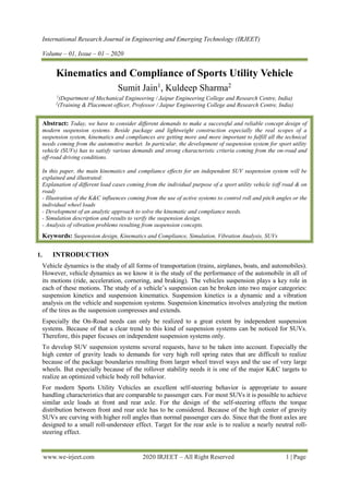
1.5.ROLL CENTER LOCATION
As the vehicle approaches a corner, the sprung mass distribution is transferred laterally from one
side to the other resulting in higher loads on the outside turning wheels. This transfer in the weight
distribution may cause the vehicle to roll depending on the roll moment acting on the vehicle. The roll
moment depends on the location of the roll center and the vehicle center of gravity, where the distance
between the roll axis and the center of gravity represents the roll moment arm. The longitudinal
position of the roll center is not considered due to the fact that it does not have a great impact on the
roll moment arm; the lateral location of the roll center on the other hand is given to be at the center line
of the vehicle. Therefore, only the vertical position of the roll center is considered when designing the
suspension geometry. By connecting the roll centers in the front and rear the vehicle roll axis is
formed. The orientation of the roll axis has a great impact on the oversteering and understeering
characterizes, designing the roll axis to be inclined towards the front of the vehicle results in
understeering, while oversteering is obtained when the roll axis is inclined towards the rear of the
vehicle.
1.6.ROLL STIFFNESS
As the vehicle approaches a corner, the sprung mass distribution is transferred laterally from one
side to the other resulting in higher loads on the outside turning wheels. This transfer in the weight
distribution may cause the vehicle to roll depending on the roll moment acting on the vehicle. The roll
moment depends on the location of the roll center and the vehicle center of gravity, where the distance
between the roll axis and the center of gravity represents the roll moment arm. The longitudinal
position of the roll center is not considered due to the fact that it does not have a great impact on the
roll moment arm; the lateral location of the roll center on the other hand is given to be at the center line
of the vehicle. Therefore, only the vertical position of the roll center is considered when designing the
suspension geometry. By connecting the roll centers in the front and rear the vehicle roll axis is
formed. The orientation of the roll axis has a great impact on the oversteering and understeering
characterizes, designing the roll axis to be inclined towards the front of the vehicle results in
understeering, while oversteering is obtained when the roll axis is inclined towards the rear of the
vehicle.
The roll stiffness is sometimes referred to as the roll rate. The roll stiffness of the suspension
system is the amount of roll moment needed to roll the suspension by one unit of rotation (degree
or radian). The roll stiffness of the suspension system is related to the ride rate through the
following equation.
𝐾 =
[(12) ∗ (𝑘𝑟) ∗ (𝑡)2]
2
6. International Research Journal in Engineering and Emerging Technology (IRJEET)
Volume – 01, Issue – 01 – 2020
www.we-irjeet.com 2020 IRJEET – All Right Reserved 6 | Page
Roll stiffness as a function of ride rate
Note, the roll stiffness resulted will be in units of lb-ft/rad, the ride rate is in units of lb/in and the
track is in units of feet.
2. CALCULATION FOR ROLL GRADIENT
Weight on front wheels = 2040lb
Weight on rear wheels = 1360 lb
Total weight = 3040lb
Dimensions:
Wheel base = 9.5ft.
H1 (C.G. height from ground) = 1.5 ft
H2 (C.G. to roll axis) = 1.1ft
The cornering conditions is left hand turn where: α = -10deg. (roadway bank angle)
R (turning radius) = 600 ft.
V (Velocity) = 100 mph = 146.7 ft/sec.
Zrf (roll axis height, front-axle) = 0.25ft (above ground)
Zrr (roll axis height, rear-axle) = 0.625ft
We assume the roll rates:
KϕF = 70000lb.-ft/rad.= 122lb.-ft/deg
KϕR = 50000lb.-ft/rad.= 873lb.-ft/deg
Because we don’t yet know what the ride rates are, we also don’t know the roll rates (as they are
dependent on one another). We therefore have to assume roll rates values to start with. Also because
roll center locations can change with ride height and roll angles, we start with values at static design
positions.
Now, Lets calculate the Center of Gravity:
b = WF*l/WT = (2040 X 9.5) / 3400 = 5.7 ft.
a = l – b = 9.5 – 5.7 = 3.8 ft.
Next, the lateral acceleration values relative to the earth and the banked turn are calculated.
Aα = V2
/Rg = 146.72
/ (-600 X 32.2) = -1.11 g’s
AY = (Aα * cosα) – sinα = (-1.11 X cos(-10)) – sin(-10)
= -1.09 + 0.17 = -0.92 g’s
Here, Aα and AY is Horizontal lateral acceleration and Lateral acceleration in car axis system.
The effective weight of the car to the banking is:
W’ = W*(Aα (sinα) + cosα)= 3400(-1.11 sin(-10) + cos(-10))
= 3400 X 1.1776 = 4004 lb.
And, the effective front and rear axle weights are
W’F = (W’ b)/l = 4004*(5.7/9.5) = 2402 lb.
W’R = (W’ a)/l = 4004*(3.8/9.5) = 1602 lb.
The roll gradient is
Φ / AY = (-W * H2) / (KϕF + KϕR) = -3400*1.1/(70,000 + 50,000)
= -0.03117 rad/g or -1.78 deg/g
Here, Φ is body roll angle
7. International Research Journal in Engineering and Emerging Technology (IRJEET)
Volume – 01, Issue – 01 – 2020
www.we-irjeet.com 2020 IRJEET – All Right Reserved 7 | Page
CONCLUSIONS
Kinematics and compliance of a Sports Utility Vehicle have to fulfil all needs coming from both
purposes On Road and Off-Road use.
Because of the high center of gravity special demands have to be solved to guarantee a save rollover
stability and an acceptable anti-dive mechanism. Since the definition of the instantaneous center line
also influences quite strongly the self-steering characteristics of the suspension serious investigations
have to guarantee the best possible compromise. Because of the high wheel loads and lateral forces
the characteristic requests for SUVs’ bushing elements are more demanding than for conventional
passenger cars. There is a clear trend towards a very soft longitudinal spring level of the suspension
system. But to fulfil the handling demands also a strong lateral wheel lead is necessary.
Analytic approaches can build a helpful basis for the K&C concept to understand different load cases.
To develop a comprehensive K&C design that considers all relevant load cases it is necessary to
verify and optimize the development process with numerical simulations.
REFERENCES
[1] H. WALLENTOWITZ Vertikal-/Querdynamik von Kraftfahrzeugen Umdruck zur Vorlesung
Kraftfahrzeuge II Verlag fka ISBN 3-925 194-35-5 Aachen, 1. Auflage 1996
[2] W. MATSCHINSKY Radführung der Straßenfahrzeuge Springer Verlag ISBN 3-540-64155-6 Berlin,
Heidelberg, New York, 2. Auflage 1998
[3] J. REIMPELL, H. STOLL, the Automotive Chassis: Engineering Principles SAE, Inc. ISBN 1-
56091736-9 Warrendale, 1st edition 1996
[4] P. HOLDMANN, P. KÖHN, B. MÖLLER, R. WILLEMS Suspension kinematics and compliance -
measuring and simulation SAE 1998 International Congress and Exposition
[5] P. KÖHN, P. HOLDMANN Moderne Prüfstandstechnik für das Fahrwerk ATZ 100 (1998) Nr. 9
[6] P. HOLDMANN Kinematik und Elastokinematik moderner PkwRadaufhängungen Lecture within the
PhD-Procedure at the Aachen University of Technology, Aachen, May 2000
[7] Race car Vehicle Dynamics: Milliken and Milliken
[8] Car suspension and Handling: Geoffrey Donald Bastow
[9] Fundamental of vehicle dynamics: Thomas D. Gillespie