SlideShare a Scribd company logo
1 | P a g e
Advancement in inverter technology
S.NO TOPICS PAGE NO
1 INTRODUCTION
2 TECHNICAL
BACKGROUND ON
INVERTERS
3 OVERVIEW OF
ADVANCED
INVERTER
FUNCTIONS
4 IMPACTS &
CHALLENGES OF
ADVANCED
INVERTERS
ADOPTION
5 ADVANCEMENTS IN
PV INVERTER
6 SOME
ADVANCEMENTS IN
APPLICATION
7 MARKET
8 CONCLUSION
2 | P a g e
INTRODUCTION:
An inverter for a solar-mounted free-standing plant in Speyer, down the Rhine.
An inverter is an electric apparatus that changes direct current (DC) to alternating
current (AC). It is not the same thing as an alternator, which converts mechanical
energy(e.g. movement) into alternating current.
Direct current is created by devices such as batteries and solar panels. When connected,
an inverter allows these devices to provide electric power for small household devices.
The inverter does this through a complex process of electrical adjustment. From this
process, AC electric power is produced. This form of electricitycan be used to power
an electric light, a microwave oven, or some other electric machine.
3 | P a g e
An inverter usually also increases the voltage. In order to increase the voltage, the
current must be decreased, so an inverter will use a lot of current on the DC side when
only a small amount is being used on the AC side.
Inverters are made in many different sizes. They can be as small as 150 watts, or as
large as 1 megawatt (1 million watts). Smaller inverters often plug into a car's cigarette
lighter socket and provide 120 or 240 volt AC power from the car's 12 volt supply.
The earliest inverters consisted of a DC motor connected mechanically to an AC
generator. A later design often used with vacuum tube car radios consisted of a rapidly
switching relay. Modern inverters are based on MOSFET or IGBT transistors.
1.Inverters are power electronics-based devices which convert direct current (DC) to
alternating current (AC).
2. This function is fundamental to the integration of power from many sources into the
distribution system.
3.Widely used in photovoltaic, wind turbine generators and energy storage resources.
4.In these applications, inverters convert a generated or stored DC to a precisely
modulated and grid synchronized AC waveform.
5. Beyond this fundamental purpose, there exist a range of complementary,
technologically viable, and demonstrated functions that an inverter may be designed to
provide
6.As DER (Distribution Energy Resources) become incorporated onto the grid at higher
penetration levels, advances in inverter functionalities represent a significant
opportunity to improve the stability, reliability, and efficiency of the electric power
distribution system.
TECHNICAL BACKGROUND ON INVERTERS
DC to AC converters produce an AC output waveform from a DC source.
Applications include adjustable speed drives (ASD), uninterruptible power
supplies (UPS), Flexible AC transmission systems (FACTS), voltage compensators,
and photovoltaic inverters. Topologies for these converters can be separated into two
distinct categories: voltage source inverters and current source inverters. Voltage
source inverters (VSIs) are named so because the independently controlled output is a
voltage waveform. Similarly, current source inverters (CSIs) are distinct in that the
controlled AC output is a current waveform.
DC to AC power conversion is the result of power switching devices, which are
commonly fully controllable semiconductor power switches
A. Standard Inverter Key Concepts:
1.Fundamentally, an inverter is a device which converts a direct current (DC) input to
an alternating current (AC) output.
2. Inverters are used in a range of applications, including consumer power electronics,
electric vehicles, and photovoltaic and energy storage interconnections to power
distribution systems at the primary (4 kV, 13.8 kV, 27 kV, and 33 kV) and secondary
(120/240 V, 120/208 V, 240/480 V) levels.
4 | P a g e
3. In distribution applications, these devices produce a sinusoidal waveform of the
appropriate frequency.
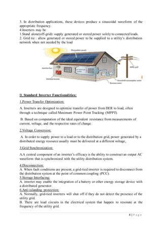
4.Inverters may be
1.Stand alone(off-grid): supply generated or stored power solely to connected loads.
2. Grid tie : allow generated or stored power to be supplied to a utility’s distribution
network when not needed by the load
B. Standard Inverter Functionalities:
1.Power Transfer Optimization:
A. Inverters are designed to optimize transfer of power from DER to load, often
through a technique called Maximum Power Point Tracking (MPPT).
B. Based on computation of the ideal equivalent resistance from measurements of
current, voltage, and the respective rates of change.
2.Voltage Conversion:
A. In order to supply power to a load or to the distribution grid, power generated by a
distributed energy resource usually must be delivered at a different voltage.
3.Grid Synchronization:
A.A central component of an inverter’s efficacy is the ability to construct an output AC
waveform that is synchronized with the utility distribution system.
4.Disconnection:
A. When fault conditions are present, a grid-tied inverter is required to disconnect from
the distribution system at the point of common coupling (PCC).
5.Storage Interfacing:
A. inverter may enable the integration of a battery or other energy storage device with
a distributed generator.
6.Anti-islanding protection:
A. Normally, grid-tied inverters will shut off if they do not detect the presence of the
utility grid.
B. There are load circuits in the electrical system that happen to resonate at the
frequency of the utility grid.
5 | P a g e
C. The inverter may be fooledinto thinking that the grid is still active even after it had
been shut down. This is called islanding.
D. An inverter designed for grid-tie operation will have anti-islanding protection built
in; it will inject small pulses that are slightly out of phase with the AC electrical system
in order to cancel any stray resonances that may be present when the grid shuts down.
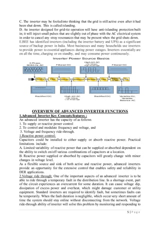
E.BEE has identified inverters (including the inverter battery and UPS) as a significant
source of backup power in India. Most businesses and many households use inverters
to provide power to essential appliances during power outages. Inverters essentially are
on all the time, charging or on standby, and may consume power continuously.
OVERVIEW OF ADVANCED INVERTER FUNCTIONS
1.Advanced Inverter Key Concepts/features :
An advanced inverter has the capacity of as follows
1. To supply or reactive power control
2. To control and modulate frequency and voltage, and
3. Voltage and frequency ride-through.
1.Reactive power control:
Capacitors could be installed to either supply or absorb reactive power. Practical
limitations include:
A. Limited variability of reactive power that can be supplied or absorbed dependent on
the ability to switch on/off various combinations of capacitors at a location.
B. Reactive power supplied or absorbed by capacitors will greatly change with minor
changes in voltage level.
As a flexible source and sink of both active and reactive power, advanced inverters
provide an opportunity for the extensive control that enables safety and reliability in
DER applications.
2.Voltage ride through: One of the important aspects of an advanced inverter is to be
able to ride through a temporary fault in the distribution line. In a shortage event, part
of the circuit experiences an overcurrent for some duration. It can cause voltage dip,
dissipation of excess power and overheat, which might damage customer or utility
equipment. Standard inverters are required to identify fault, but sometimes faults can
be temporarily. When the fault duration is negligible, which occur very short amount of
time the system should stay online without disconnecting from the network. Voltage
ride-through ability of inverter will solve this problem by monitoring and responding to
6 | P a g e
voltage fluctuations. Increase and decrease of the voltage levels can be achieved by
injecting reactive power into the line.
3.Frequency ride through: Frequency ride through Frequency ride through capability is
the same phenomena with voltage ride through capability. In this situation, when fault
occurs in the distribution network the frequency deviates from its nominal value. When
the fault is temporary, the inverter must stay online for certain time period for certain
frequency values. Frequency ride-through capability of advanced inverters resolves this
and helps the system stay online without tripping for negligible faults. Higher or lower
frequency in the system can result over or under-supply of active power to a circuit.
2.Advanced Inverter Functionalities/topologies:
Several studied has been conducted to improve the efficiency and reliability of the PV
inverters. Commonly used control strategies for inverters are employed with high
switching frequency modulation techniques such as sinusoidal pulse width modulation
(SPWM) and space vector pulse width modulation (SVPWM), and for fundamental
switching frequency modulation space vector control (SVC) and selective harmonic
elimination (SHE) techniques are used. Depending on the power electronics circuit
design topologies of the inverters used in PV applications, can be classifiedas voltage
source Inverters, Current source inverters, and multilevel inverters, see Table.
S. No: Topologies configuration Modulation Components
1. VSI 1-ph(half &full
bridge)
SPWM,
Hysteresis
IGBT,
MOSFET
2. CSI 3-ph full bridge SPWM Diodes,
Capacitors
3. Multilevel
inverter
Trinary hybrid
(H-bridge),
Laddered,
super-lift
modulated,
switched
capacitor,
switched
inductor
SPWM,
SVPWM,
SVC,
SHE.
Power switches,
Capacitors,
Inductors
1.Reactive Power Control:
A. Definition: The presence of inductive loads results in a phase difference between
voltage and current waveforms, causing losses which reduce the efficiency of real
power distribution.
B. Less efficientpower distribution requires greater current, which magnifies the impact
of line losses.
7 | P a g e
Implementation:
8 | P a g e
1.The supply of reactive power via capacitors will cause the phase of the current to lead
that of the voltage, while the opposite may be achieved when an inductive load absorbs
reactive power.
2.Integrated thyristor-switched capacitors and capacitors, functioning together as a
Flexible AC Transmission System (FACTS), Solid-state- and power electronics-based
compensators, allow increasingly rapid and exact provision of reactive power.
3.Advanced inverters, combined with existing FACTS infrastructure and control
Systems.
5.A capability curve prescribes the output reactive power, which is diminished at lower
voltage levels and at higher output active power.
6.These inverters control power factor according to the characteristic capability curve
in order to match the mix of resistive and inductive loads on the circuit.
Impacts:
1.significant potential to increase efficiency and flexibility of power distribution.
2.providing sufficient resolution in controlling reactive power.
3.precise modulation of reactive power supplied to the conductor and load
2.Voltage and Frequency Ride-Through:
A. Definition: Ride-through may be defined as the ability of an electronic device to
respond appropriately to a temporary fault in the distribution line to which the device is
connected.
B. Standard inverters are required to identify a typical fault and disconnect from the
circuit when a fault is detected.
C. This course of action will inhibit the DER’s operationand prevent it from functioning
under the restored normal conditions.
D. The voltage and frequency ride-through functionalities provide dynamic support to
the grid.
E. In responding actively to atypical conditions, ride-through executes the required
disconnection in the case of an irresolvable, permanent fault, and can prevent
disconnection in cases where these conditions result from temporary or isolated events.
F. The avoidance of “unnecessary” disconnection improves grid reliability by enabling
the DER to continue to supply power and support functions to the grid.
G. A cautionary note is that there are risks associated with ride-through functionalities,
especially in non-utility scale DER applications such as residential and small
commercial.
H. If ride-through is permitted to prolong the presence of a fault, this could expose
equipment and people to greater risk of damage or injury (or even death).
Implementation:
A. Ride-through capabilities are tied to measurements of the distribution system’s AC
frequency and voltage.
B. Ride-through functionality is highly dependent on monitoring, processing, and
algorithmic response.
C. controlling algorithm will implement a response, such as an increase in power in
response to a low voltage.
D. If the condition persists and the inverter fails to reach sufficient parameters within the
IEEE 1547 disconnection time frame, the disconnection will take place as with the
standard inverter, ceasing all ride-through responses.
9 | P a g e
E. Sags and swells in voltage levels can be remedied by the injection of reactive power
into the line.
Disadvantage: In non-utility scale DER applications such as residential and small
commercial, if ride-through is permitted by standards to prolong the presence of a
fault, people will use a fault circuit to greater risk of damage.
IMPACTS & CHALLENGES OF ADVANCED INVERTERS
ADOPTION
Impacts:
1.reactive power control increases efficiency of power distribution by reducing
line losses.
2.The voltage and frequency ride-through functionalities provide dynamic grid
supportin the presence of a fault along the interconnected line.
3.Avoiding “unnecessary” disconnection, especially of large distributed energy
resources, could improve grid reliability.
4.The widespread integration of DERs into the power distribution network presents a
number of technical challenges which advanced inverter functionalities could help
mitigate.
5.At its core, reactive power control increases efficiency of power distribution by
reducing line losses.
6.The efficacy of VAR control is highly dependent on geographic proximity to the
line or feeder that requires support, and DER inverters are therefore a logical source of
reactive power.
7.The power quality benefits may be implemented statically, through scheduling, or
dynamically, using predefined settings and modes.
8. Avoiding “unnecessary” disconnection, especially of large distributed energy
resources, could improve grid reliability.
Challenges:
1.These inverters should be integrated with utility distribution management systems.
Advanced functionalities would work with integration of inverters with data
management system
2. Different safety requirements and standards are to be implemented for residential and
small commercial applications.
3.EPRI(Electric power Research Institute) conducting a study indicating that over 69%
of downtime events are caused by PV inverters.
4.The main contributors to these failures were software bugs material failures indicating
that ,which indicates a need for significant refining of the inverter technologies being
developed.
5. Without this ability, there will be limitations to how much these advanced
functionalities can be used autonomously without adversely impacting the grid or other
customers’ equipment.
6.Power quality may be another challenge with more use of inverters producing current
harmonics which then emanate onto the grid.
ADVANCEMENTS IN PV INVERTER
10 | P a g e
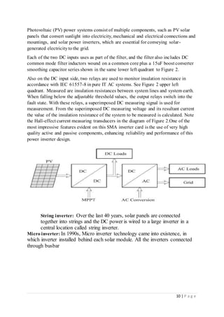
Photovoltaic (PV) power systems consist of multiple components, such as PV solar
panels that convert sunlight into electricity, mechanical and electrical connections and
mountings, and solar power inverters, which are essential for conveying solar-
generated electricityto the grid.
Each of the two DC inputs uses as part of the filter, and the filter also includes DC
common mode filter inductors wound on a common core plus a 15uF boost converter
smoothing capacitor series shown in the same lower left quadrant to Figure 2.
Also on the DC input side, two relays are used to monitor insulation resistance in
accordance with IEC 61557-8 in pure IT AC systems. See Figure 2 upper left
quadrant. Measured are insulation resistances between system lines and system earth.
When falling below the adjustable threshold values, the output relays switch into the
fault state. With these relays, a superimposed DC measuring signal is used for
measurement. From the superimposed DC measuring voltage and its resultant current
the value of the insulation resistance of the system to be measured is calculated. Note
the Hall-effect current measuring transducers in the diagram of Figure 2.One of the
most impressive features evident on this SMA inverter card is the use of very high
quality active and passive components, enhancing reliability and performance of this
power inverter design.
String inverter: Over the last 40 years, solar panels are connected
together into strings and the DC power is wired to a large inverter in a
central location called string inverter.
Micro inverter: In 1990s, Micro inverter technology came into existence, in
which inverter installed behind each solar module. All the inverters connected
through busbar
11 | P a g e
String inverter Micro inverter
1. Using a string inverter, the solar
panel array, still typically rated at 12V,
24V or 48V each panel (although higher
voltage panels are now coming out) is
wired in series, rather than in parallel.
1. A micro-inverter converts power at
the solar panel from DC electricity to
240V AC electricity and is attached to
each panel in a solar system.
2. A string inverter will usually be
located a short distance away from the
array in a sheltered location between the
solar array and the switchboard.
2. They are also useful on roofs that are
too small to enable a string of panels to be
installed.
3. This is the most common type of
inverter used in residential and small /
medium commercial systems .
3. With more inverters there are
potentially more chances of a
failure.. Micro inverters have now been
used for a number of years and offer s
solid solution as an alternative to string
inverters.
Advantages:
1.Allows for high design flexibility
2.High efficiency
3.Robust
4.3 phase variations available
5.Low cost
6.Well supported (if buying trusted
brands)
7.Remote system monitoring capabilities
Advantages:
1.Panel level MPPT (Maximum Power
Point Tracking).
2. Panel level monitoring.
3. No need to calculate string lengths –
simpler to design systems.
4.Allows for increased design flexibility,
modules can be oriented in different
directions
12 | P a g e
Disadvantages:
1.No panel level MPPT*
2.No panel level monitoring*
3.High voltage levels present a potential
safety hazard
Disadvantages:
1.Allows for increased design flexibility,
modules can be oriented in different
directions.
2. Increased maintenance costs due to
there being multiple units in an array.
3. Given their positioning in an
installation, some micro-inverters may
have issues in extreme heat
SOME ADVANCEMENTS IN APPLICATION
There are two main types of solar technology: photovoltaics (PV) and concentrated
solar power (CSP). Solar PV technology captures sunlight to generate electric power,
and CSP harnesses the sun’s heat and uses it to generate thermal energy that powers
heaters or turbines.
1.A microwave inverter is a system used in microwave powering which uses inverter
power supply as opposed to traditional magnetic coils or transformers. It is more
efficient and powerful.
2.Other applications include welding, HVDC, UPS, LCD screen, Electric tasers, Hybrid
vehicles etc.
Solar technology:
1.Solar skin design
2.solar powered roads
3.Wearable solar
4.Solar batteries: innovation in solar storage.
Advances in solar energy:
1.Solar tracking mounts
2.Advances in solar panel efficiency
3.Solar thermal fuel(STF)
4.Solar water purifier
13 | P a g e
MARKET
Few of the major players operating in India inverter market include Luminous
Power Technologies Pvt. Ltd., V-Guard Industries, Microtek International Private
Limited, Su-Kam Power Systems Limited, Exide Industries Limited, Amara Raja
Batteries Limited, Genus Innovation Limited, Arise India Limited, Consul Neo-watt
Power Solutions Private Limited, and Uni-line Energy Systems Private Limited.
The market is dominated by utility sector owing to its large scale solar projects
deploying large number of solar inverters. Further, commercial segment is anticipated
to exhibit highest growth rate during the forecast period. The high growth is attributed
to growing solar installations across educational institutes, offices, factories, hospitals,
and warehouses.
The report provides detailedanalysis of the following market segments:
1.By Types:
A. Central Inverter
B. String Inverter
C. Micro Inverter
2.By System Types:
A. Off Grid
14 | P a g e
B. On Grid
3.By End Users:
A. Commercial
B. B. Utility
C. Residential
4.By Power Ratings:
A Below 10 kW
B.10 kW - 100 kW
C. 100.1 kW - 1 MW
D.Above 1 MW
5.By Regions:
A. Northern
B. Eastern
C. Western
D. Southern
6.Companies Mentioned
A.ABB India Ltd.
B.SMA Solar India Pvt. Ltd.
C. Delta India Electronics Pvt. Ltd.
D. Chint Electric India Pvt. Ltd.
E. Schneider Electric India Pvt. Ltd.
F. Hitachi Hi-Rel Power Electronics Pvt. Ltd.
G. Toshiba Mitsubishi-Electric Industrial Systems Corporation
15 | P a g e
CONCLUSION
The user interactive solar PV cell/array model utilises the graphical user interface
feature. It is used for the simulation study of the solar PV based grid interactive inverter
system. The characteristics of solar PV array used with the grid interactive inverter
prototype circuits are used to validate the model. A novel scheme for operating the PV
array at maximum power point without using a dc-to-dc converter has also been
developed. The scheme is successfully applied to the proposed discontinuous phase
control technique based inverter as well as proposed multi-stage inverters. For
discontinuous phase control technique based inverter, the MPPT scheme utilizes two
step control depending on the insolation level. The MPPT control algorithm switches
the thyristors for higher and lower insolation thereby operating the PV array at the
maximum power point.
1.Advanced inverter functionalities may lend significant improvement to the stability,
reliability, and efficiency, of the electric power distribution system.
2.Distribution automation systems implemented by utilities will be central to the
integration of these functionalities, which require protection, control, and
communication to reach full efficacy.
3.Standards for interoperability and performance are being revised to consider safe and
reliable augmentation of inverter functionality to support increased penetration of DER.

More Related Content

What's hot

Power system stability
Power  system  stabilityPower  system  stability
Power system stability
rohit kumar
 
Simulation based minor project on Buck converter( DC to Dc step down Converter)
Simulation based minor project on Buck converter( DC to Dc step down Converter)Simulation based minor project on Buck converter( DC to Dc step down Converter)
Simulation based minor project on Buck converter( DC to Dc step down Converter)
Ashutosh Singh
 
Compensation of harmonic currents utilizing AHC by kingsprime
Compensation of harmonic currents utilizing AHC by kingsprimeCompensation of harmonic currents utilizing AHC by kingsprime
Compensation of harmonic currents utilizing AHC by kingsprime
Kalu Kingsley Ekperebuike
 
Design & Analysis of Grid Connected Photovoltaic System
Design & Analysis of Grid Connected Photovoltaic SystemDesign & Analysis of Grid Connected Photovoltaic System
Design & Analysis of Grid Connected Photovoltaic System
Sulaman Muhammad
 
Policies for smart grid
Policies for smart gridPolicies for smart grid
Policies for smart grid
Ashfaq khan
 
high power converter and ac drives.pdf
high power converter and ac drives.pdfhigh power converter and ac drives.pdf
high power converter and ac drives.pdf
SoumyadeepRoy48
 
EXCITATION SYSTEMS by Dr. Kundur Power Systems
EXCITATION SYSTEMS by Dr. Kundur Power SystemsEXCITATION SYSTEMS by Dr. Kundur Power Systems
EXCITATION SYSTEMS by Dr. Kundur Power Systems
Power System Operation
 
Loading Capability Limits of Transmission Lines
Loading Capability Limits of Transmission LinesLoading Capability Limits of Transmission Lines
Loading Capability Limits of Transmission Lines
Raja Adapa
 
Atc calculation methods by shridhar kulkarni
Atc calculation methods by shridhar kulkarniAtc calculation methods by shridhar kulkarni
Atc calculation methods by shridhar kulkarni
Shridhar kulkarni
 
INTERLINE FLOW CONTROLLER
INTERLINE FLOW CONTROLLERINTERLINE FLOW CONTROLLER
INTERLINE FLOW CONTROLLER
Nitish NIT
 
Thyristor switched capacitor PPT
Thyristor switched capacitor PPTThyristor switched capacitor PPT
Thyristor switched capacitor PPT
KLS' S GIT, BELGAUM
 
distributed power flow controller
distributed power flow controllerdistributed power flow controller
distributed power flow controller
Kesava Varma
 
Power Quality & Power Quality Problems
Power Quality & Power Quality ProblemsPower Quality & Power Quality Problems
Power Quality & Power Quality Problems
Power System Operation
 
upfc
upfcupfc
Grid Integration of Renewables: Challenges and Solutions
Grid Integration of Renewables: Challenges and SolutionsGrid Integration of Renewables: Challenges and Solutions
Grid Integration of Renewables: Challenges and Solutions
Power System Operation
 
Importing/Exporting a project using DIgSILENT PowerFactory
Importing/Exporting a project using DIgSILENT PowerFactoryImporting/Exporting a project using DIgSILENT PowerFactory
Importing/Exporting a project using DIgSILENT PowerFactory
Francisco Gonzalez-Longatt
 
Relay
RelayRelay
Fc tcr.newpptx
Fc tcr.newpptxFc tcr.newpptx
Fc tcr.newpptx
Rakshita Upadhyay
 
Multi terminal dc systems (mtdc)
Multi terminal dc systems (mtdc)Multi terminal dc systems (mtdc)
Multi terminal dc systems (mtdc)
jawaharramaya
 
Project on STATCOM
Project on STATCOMProject on STATCOM
Project on STATCOM
Sutirtha Das
 

What's hot (20)

Power system stability
Power  system  stabilityPower  system  stability
Power system stability
 
Simulation based minor project on Buck converter( DC to Dc step down Converter)
Simulation based minor project on Buck converter( DC to Dc step down Converter)Simulation based minor project on Buck converter( DC to Dc step down Converter)
Simulation based minor project on Buck converter( DC to Dc step down Converter)
 
Compensation of harmonic currents utilizing AHC by kingsprime
Compensation of harmonic currents utilizing AHC by kingsprimeCompensation of harmonic currents utilizing AHC by kingsprime
Compensation of harmonic currents utilizing AHC by kingsprime
 
Design & Analysis of Grid Connected Photovoltaic System
Design & Analysis of Grid Connected Photovoltaic SystemDesign & Analysis of Grid Connected Photovoltaic System
Design & Analysis of Grid Connected Photovoltaic System
 
Policies for smart grid
Policies for smart gridPolicies for smart grid
Policies for smart grid
 
high power converter and ac drives.pdf
high power converter and ac drives.pdfhigh power converter and ac drives.pdf
high power converter and ac drives.pdf
 
EXCITATION SYSTEMS by Dr. Kundur Power Systems
EXCITATION SYSTEMS by Dr. Kundur Power SystemsEXCITATION SYSTEMS by Dr. Kundur Power Systems
EXCITATION SYSTEMS by Dr. Kundur Power Systems
 
Loading Capability Limits of Transmission Lines
Loading Capability Limits of Transmission LinesLoading Capability Limits of Transmission Lines
Loading Capability Limits of Transmission Lines
 
Atc calculation methods by shridhar kulkarni
Atc calculation methods by shridhar kulkarniAtc calculation methods by shridhar kulkarni
Atc calculation methods by shridhar kulkarni
 
INTERLINE FLOW CONTROLLER
INTERLINE FLOW CONTROLLERINTERLINE FLOW CONTROLLER
INTERLINE FLOW CONTROLLER
 
Thyristor switched capacitor PPT
Thyristor switched capacitor PPTThyristor switched capacitor PPT
Thyristor switched capacitor PPT
 
distributed power flow controller
distributed power flow controllerdistributed power flow controller
distributed power flow controller
 
Power Quality & Power Quality Problems
Power Quality & Power Quality ProblemsPower Quality & Power Quality Problems
Power Quality & Power Quality Problems
 
upfc
upfcupfc
upfc
 
Grid Integration of Renewables: Challenges and Solutions
Grid Integration of Renewables: Challenges and SolutionsGrid Integration of Renewables: Challenges and Solutions
Grid Integration of Renewables: Challenges and Solutions
 
Importing/Exporting a project using DIgSILENT PowerFactory
Importing/Exporting a project using DIgSILENT PowerFactoryImporting/Exporting a project using DIgSILENT PowerFactory
Importing/Exporting a project using DIgSILENT PowerFactory
 
Relay
RelayRelay
Relay
 
Fc tcr.newpptx
Fc tcr.newpptxFc tcr.newpptx
Fc tcr.newpptx
 
Multi terminal dc systems (mtdc)
Multi terminal dc systems (mtdc)Multi terminal dc systems (mtdc)
Multi terminal dc systems (mtdc)
 
Project on STATCOM
Project on STATCOMProject on STATCOM
Project on STATCOM
 

Similar to Inverter doc

Ppt of inverter.1
Ppt of inverter.1Ppt of inverter.1
Ppt of inverter.1
Pavan Kumar Mallepoola
 
Advancements in inverter technology
Advancements  in inverter technologyAdvancements  in inverter technology
Advancements in inverter technology
Bhanu Teja
 
Hybrid inverter project report
Hybrid inverter project reportHybrid inverter project report
Hybrid inverter project report
Erole technologies Pvt. Ltd
 
PROJECT TOPIC ON INSTALLATION OF INVERTER IN A LABORATORY
PROJECT TOPIC ON INSTALLATION OF INVERTER IN A LABORATORYPROJECT TOPIC ON INSTALLATION OF INVERTER IN A LABORATORY
PROJECT TOPIC ON INSTALLATION OF INVERTER IN A LABORATORY
SAMUEL BARNABAS IFITUMI
 
Power Quality Analysis Using Active NPC Multilevel inverter in PV sourced sta...
Power Quality Analysis Using Active NPC Multilevel inverter in PV sourced sta...Power Quality Analysis Using Active NPC Multilevel inverter in PV sourced sta...
Power Quality Analysis Using Active NPC Multilevel inverter in PV sourced sta...
IRJET Journal
 
Power Quality Analysis Using Active NPC Multilevel inverter in PV sourced sta...
Power Quality Analysis Using Active NPC Multilevel inverter in PV sourced sta...Power Quality Analysis Using Active NPC Multilevel inverter in PV sourced sta...
Power Quality Analysis Using Active NPC Multilevel inverter in PV sourced sta...
IRJET Journal
 
Review of Reduction of Leakage Current in Cascaded Multilevel Inverter
Review of Reduction of Leakage Current in Cascaded Multilevel InverterReview of Reduction of Leakage Current in Cascaded Multilevel Inverter
Review of Reduction of Leakage Current in Cascaded Multilevel Inverter
IJRST Journal
 
Grid Voltage Regulation
Grid Voltage RegulationGrid Voltage Regulation
Grid Voltage Regulation
Aditya Nehwal
 
Comparison of upqc and dvr in wind turbine fed fsig under asymmetric faults
Comparison of upqc and dvr in wind turbine fed fsig under asymmetric faultsComparison of upqc and dvr in wind turbine fed fsig under asymmetric faults
Comparison of upqc and dvr in wind turbine fed fsig under asymmetric faults
elelijjournal
 
Smart Wireless Battery Charger with Charging Monitor: A Review
Smart Wireless Battery Charger with Charging Monitor: A ReviewSmart Wireless Battery Charger with Charging Monitor: A Review
Smart Wireless Battery Charger with Charging Monitor: A Review
IRJET Journal
 
Q4502102105
Q4502102105Q4502102105
Q4502102105
IJERA Editor
 
Report on 220kv substation at Jassure
Report on 220kv substation at JassureReport on 220kv substation at Jassure
Report on 220kv substation at Jassure
Shuvam Pathania
 
Design and Construction of 2KVA AC/DC Inverter
Design and Construction of 2KVA AC/DC InverterDesign and Construction of 2KVA AC/DC Inverter
Design and Construction of 2KVA AC/DC Inverter
Obasan Kehinde Olusegun Hussein
 
Photo Voltaic Cell Integrated DVR for Power Quality Improvement
Photo Voltaic Cell Integrated DVR for Power Quality ImprovementPhoto Voltaic Cell Integrated DVR for Power Quality Improvement
Photo Voltaic Cell Integrated DVR for Power Quality Improvement
IJMTST Journal
 
1660034363151685.pptx
1660034363151685.pptx1660034363151685.pptx
1660034363151685.pptx
Pradip khatri
 
Module 4 power generation & Economics - Substation vtu syllabus
Module 4 power generation & Economics - Substation vtu syllabusModule 4 power generation & Economics - Substation vtu syllabus
Module 4 power generation & Economics - Substation vtu syllabus
DrCVMOHAN
 
Components of intervers - Multi level inverter
Components of intervers - Multi level inverterComponents of intervers - Multi level inverter
Components of intervers - Multi level inverter
ssuser39e462
 
Implementation of a Microcontroller Base Single Phase Automatic Changeover
Implementation of a Microcontroller Base Single Phase Automatic Changeover Implementation of a Microcontroller Base Single Phase Automatic Changeover
Implementation of a Microcontroller Base Single Phase Automatic Changeover
IJSRED
 
Modeling of single phase off-grid inverter for small standalone system applic...
Modeling of single phase off-grid inverter for small standalone system applic...Modeling of single phase off-grid inverter for small standalone system applic...
Modeling of single phase off-grid inverter for small standalone system applic...
International Journal of Power Electronics and Drive Systems
 
IRJET-Management of power factor and harmonic
IRJET-Management of power factor and harmonicIRJET-Management of power factor and harmonic
IRJET-Management of power factor and harmonic
IRJET Journal
 

Similar to Inverter doc (20)

Ppt of inverter.1
Ppt of inverter.1Ppt of inverter.1
Ppt of inverter.1
 
Advancements in inverter technology
Advancements  in inverter technologyAdvancements  in inverter technology
Advancements in inverter technology
 
Hybrid inverter project report
Hybrid inverter project reportHybrid inverter project report
Hybrid inverter project report
 
PROJECT TOPIC ON INSTALLATION OF INVERTER IN A LABORATORY
PROJECT TOPIC ON INSTALLATION OF INVERTER IN A LABORATORYPROJECT TOPIC ON INSTALLATION OF INVERTER IN A LABORATORY
PROJECT TOPIC ON INSTALLATION OF INVERTER IN A LABORATORY
 
Power Quality Analysis Using Active NPC Multilevel inverter in PV sourced sta...
Power Quality Analysis Using Active NPC Multilevel inverter in PV sourced sta...Power Quality Analysis Using Active NPC Multilevel inverter in PV sourced sta...
Power Quality Analysis Using Active NPC Multilevel inverter in PV sourced sta...
 
Power Quality Analysis Using Active NPC Multilevel inverter in PV sourced sta...
Power Quality Analysis Using Active NPC Multilevel inverter in PV sourced sta...Power Quality Analysis Using Active NPC Multilevel inverter in PV sourced sta...
Power Quality Analysis Using Active NPC Multilevel inverter in PV sourced sta...
 
Review of Reduction of Leakage Current in Cascaded Multilevel Inverter
Review of Reduction of Leakage Current in Cascaded Multilevel InverterReview of Reduction of Leakage Current in Cascaded Multilevel Inverter
Review of Reduction of Leakage Current in Cascaded Multilevel Inverter
 
Grid Voltage Regulation
Grid Voltage RegulationGrid Voltage Regulation
Grid Voltage Regulation
 
Comparison of upqc and dvr in wind turbine fed fsig under asymmetric faults
Comparison of upqc and dvr in wind turbine fed fsig under asymmetric faultsComparison of upqc and dvr in wind turbine fed fsig under asymmetric faults
Comparison of upqc and dvr in wind turbine fed fsig under asymmetric faults
 
Smart Wireless Battery Charger with Charging Monitor: A Review
Smart Wireless Battery Charger with Charging Monitor: A ReviewSmart Wireless Battery Charger with Charging Monitor: A Review
Smart Wireless Battery Charger with Charging Monitor: A Review
 
Q4502102105
Q4502102105Q4502102105
Q4502102105
 
Report on 220kv substation at Jassure
Report on 220kv substation at JassureReport on 220kv substation at Jassure
Report on 220kv substation at Jassure
 
Design and Construction of 2KVA AC/DC Inverter
Design and Construction of 2KVA AC/DC InverterDesign and Construction of 2KVA AC/DC Inverter
Design and Construction of 2KVA AC/DC Inverter
 
Photo Voltaic Cell Integrated DVR for Power Quality Improvement
Photo Voltaic Cell Integrated DVR for Power Quality ImprovementPhoto Voltaic Cell Integrated DVR for Power Quality Improvement
Photo Voltaic Cell Integrated DVR for Power Quality Improvement
 
1660034363151685.pptx
1660034363151685.pptx1660034363151685.pptx
1660034363151685.pptx
 
Module 4 power generation & Economics - Substation vtu syllabus
Module 4 power generation & Economics - Substation vtu syllabusModule 4 power generation & Economics - Substation vtu syllabus
Module 4 power generation & Economics - Substation vtu syllabus
 
Components of intervers - Multi level inverter
Components of intervers - Multi level inverterComponents of intervers - Multi level inverter
Components of intervers - Multi level inverter
 
Implementation of a Microcontroller Base Single Phase Automatic Changeover
Implementation of a Microcontroller Base Single Phase Automatic Changeover Implementation of a Microcontroller Base Single Phase Automatic Changeover
Implementation of a Microcontroller Base Single Phase Automatic Changeover
 
Modeling of single phase off-grid inverter for small standalone system applic...
Modeling of single phase off-grid inverter for small standalone system applic...Modeling of single phase off-grid inverter for small standalone system applic...
Modeling of single phase off-grid inverter for small standalone system applic...
 
IRJET-Management of power factor and harmonic
IRJET-Management of power factor and harmonicIRJET-Management of power factor and harmonic
IRJET-Management of power factor and harmonic
 

Recently uploaded

LORRAINE ANDREI_LEQUIGAN_GOOGLE CALENDAR
LORRAINE ANDREI_LEQUIGAN_GOOGLE CALENDARLORRAINE ANDREI_LEQUIGAN_GOOGLE CALENDAR
LORRAINE ANDREI_LEQUIGAN_GOOGLE CALENDAR
lorraineandreiamcidl
 
按照学校原版(Adelaide文凭证书)阿德莱德大学毕业证快速办理
按照学校原版(Adelaide文凭证书)阿德莱德大学毕业证快速办理按照学校原版(Adelaide文凭证书)阿德莱德大学毕业证快速办理
按照学校原版(Adelaide文凭证书)阿德莱德大学毕业证快速办理
terpt4iu
 
一比一原版(Monash文凭证书)莫纳什大学毕业证如何办理
一比一原版(Monash文凭证书)莫纳什大学毕业证如何办理一比一原版(Monash文凭证书)莫纳什大学毕业证如何办理
一比一原版(Monash文凭证书)莫纳什大学毕业证如何办理
xuqdabu
 
按照学校原版(Greenwich文凭证书)格林威治大学毕业证快速办理
按照学校原版(Greenwich文凭证书)格林威治大学毕业证快速办理按照学校原版(Greenwich文凭证书)格林威治大学毕业证快速办理
按照学校原版(Greenwich文凭证书)格林威治大学毕业证快速办理
yizxn4sx
 
按照学校原版(UAL文凭证书)伦敦艺术大学毕业证快速办理
按照学校原版(UAL文凭证书)伦敦艺术大学毕业证快速办理按照学校原版(UAL文凭证书)伦敦艺术大学毕业证快速办理
按照学校原版(UAL文凭证书)伦敦艺术大学毕业证快速办理
yizxn4sx
 
按照学校原版(UOL文凭证书)利物浦大学毕业证快速办理
按照学校原版(UOL文凭证书)利物浦大学毕业证快速办理按照学校原版(UOL文凭证书)利物浦大学毕业证快速办理
按照学校原版(UOL文凭证书)利物浦大学毕业证快速办理
terpt4iu
 
加急办理美国南加州大学毕业证文凭毕业证原版一模一样
加急办理美国南加州大学毕业证文凭毕业证原版一模一样加急办理美国南加州大学毕业证文凭毕业证原版一模一样
加急办理美国南加州大学毕业证文凭毕业证原版一模一样
u0g33km
 
Production.pptxd dddddddddddddddddddddddddddddddddd
Production.pptxd ddddddddddddddddddddddddddddddddddProduction.pptxd dddddddddddddddddddddddddddddddddd
Production.pptxd dddddddddddddddddddddddddddddddddd
DanielOliver74
 
一比一原版(ANU文凭证书)澳大利亚国立大学毕业证如何办理
一比一原版(ANU文凭证书)澳大利亚国立大学毕业证如何办理一比一原版(ANU文凭证书)澳大利亚国立大学毕业证如何办理
一比一原版(ANU文凭证书)澳大利亚国立大学毕业证如何办理
nudduv
 
按照学校原版(Columbia文凭证书)哥伦比亚大学毕业证快速办理
按照学校原版(Columbia文凭证书)哥伦比亚大学毕业证快速办理按照学校原版(Columbia文凭证书)哥伦比亚大学毕业证快速办理
按照学校原版(Columbia文凭证书)哥伦比亚大学毕业证快速办理
uyesp1a
 
按照学校原版(KCL文凭证书)伦敦国王学院毕业证快速办理
按照学校原版(KCL文凭证书)伦敦国王学院毕业证快速办理按照学校原版(KCL文凭证书)伦敦国王学院毕业证快速办理
按照学校原版(KCL文凭证书)伦敦国王学院毕业证快速办理
terpt4iu
 
1比1复刻澳洲皇家墨尔本理工大学毕业证本科学位原版一模一样
1比1复刻澳洲皇家墨尔本理工大学毕业证本科学位原版一模一样1比1复刻澳洲皇家墨尔本理工大学毕业证本科学位原版一模一样
1比1复刻澳洲皇家墨尔本理工大学毕业证本科学位原版一模一样
2g3om49r
 
按照学校原版(UVic文凭证书)维多利亚大学毕业证快速办理
按照学校原版(UVic文凭证书)维多利亚大学毕业证快速办理按照学校原版(UVic文凭证书)维多利亚大学毕业证快速办理
按照学校原版(UVic文凭证书)维多利亚大学毕业证快速办理
1jtj7yul
 
一比一原版(TheAuckland毕业证书)新西兰奥克兰大学毕业证如何办理
一比一原版(TheAuckland毕业证书)新西兰奥克兰大学毕业证如何办理一比一原版(TheAuckland毕业证书)新西兰奥克兰大学毕业证如何办理
一比一原版(TheAuckland毕业证书)新西兰奥克兰大学毕业证如何办理
xuqdabu
 
一比一原版(Greenwich文凭证书)格林威治大学毕业证如何办理
一比一原版(Greenwich文凭证书)格林威治大学毕业证如何办理一比一原版(Greenwich文凭证书)格林威治大学毕业证如何办理
一比一原版(Greenwich文凭证书)格林威治大学毕业证如何办理
byfazef
 
一比一原版(UQ文凭证书)昆士兰大学毕业证如何办理
一比一原版(UQ文凭证书)昆士兰大学毕业证如何办理一比一原版(UQ文凭证书)昆士兰大学毕业证如何办理
一比一原版(UQ文凭证书)昆士兰大学毕业证如何办理
xuqdabu
 
一比一原版(Adelaide文凭证书)阿德莱德大学毕业证如何办理
一比一原版(Adelaide文凭证书)阿德莱德大学毕业证如何办理一比一原版(Adelaide文凭证书)阿德莱德大学毕业证如何办理
一比一原版(Adelaide文凭证书)阿德莱德大学毕业证如何办理
nudduv
 
一比一原版(Adelaide文凭证书)阿德莱德大学毕业证如何办理
一比一原版(Adelaide文凭证书)阿德莱德大学毕业证如何办理一比一原版(Adelaide文凭证书)阿德莱德大学毕业证如何办理
一比一原版(Adelaide文凭证书)阿德莱德大学毕业证如何办理
xuqdabu
 
按照学校原版(QU文凭证书)皇后大学毕业证快速办理
按照学校原版(QU文凭证书)皇后大学毕业证快速办理按照学校原版(QU文凭证书)皇后大学毕业证快速办理
按照学校原版(QU文凭证书)皇后大学毕业证快速办理
8db3cz8x
 
按照学校原版(UST文凭证书)圣托马斯大学毕业证快速办理
按照学校原版(UST文凭证书)圣托马斯大学毕业证快速办理按照学校原版(UST文凭证书)圣托马斯大学毕业证快速办理
按照学校原版(UST文凭证书)圣托马斯大学毕业证快速办理
zpc0z12
 

Recently uploaded (20)

LORRAINE ANDREI_LEQUIGAN_GOOGLE CALENDAR
LORRAINE ANDREI_LEQUIGAN_GOOGLE CALENDARLORRAINE ANDREI_LEQUIGAN_GOOGLE CALENDAR
LORRAINE ANDREI_LEQUIGAN_GOOGLE CALENDAR
 
按照学校原版(Adelaide文凭证书)阿德莱德大学毕业证快速办理
按照学校原版(Adelaide文凭证书)阿德莱德大学毕业证快速办理按照学校原版(Adelaide文凭证书)阿德莱德大学毕业证快速办理
按照学校原版(Adelaide文凭证书)阿德莱德大学毕业证快速办理
 
一比一原版(Monash文凭证书)莫纳什大学毕业证如何办理
一比一原版(Monash文凭证书)莫纳什大学毕业证如何办理一比一原版(Monash文凭证书)莫纳什大学毕业证如何办理
一比一原版(Monash文凭证书)莫纳什大学毕业证如何办理
 
按照学校原版(Greenwich文凭证书)格林威治大学毕业证快速办理
按照学校原版(Greenwich文凭证书)格林威治大学毕业证快速办理按照学校原版(Greenwich文凭证书)格林威治大学毕业证快速办理
按照学校原版(Greenwich文凭证书)格林威治大学毕业证快速办理
 
按照学校原版(UAL文凭证书)伦敦艺术大学毕业证快速办理
按照学校原版(UAL文凭证书)伦敦艺术大学毕业证快速办理按照学校原版(UAL文凭证书)伦敦艺术大学毕业证快速办理
按照学校原版(UAL文凭证书)伦敦艺术大学毕业证快速办理
 
按照学校原版(UOL文凭证书)利物浦大学毕业证快速办理
按照学校原版(UOL文凭证书)利物浦大学毕业证快速办理按照学校原版(UOL文凭证书)利物浦大学毕业证快速办理
按照学校原版(UOL文凭证书)利物浦大学毕业证快速办理
 
加急办理美国南加州大学毕业证文凭毕业证原版一模一样
加急办理美国南加州大学毕业证文凭毕业证原版一模一样加急办理美国南加州大学毕业证文凭毕业证原版一模一样
加急办理美国南加州大学毕业证文凭毕业证原版一模一样
 
Production.pptxd dddddddddddddddddddddddddddddddddd
Production.pptxd ddddddddddddddddddddddddddddddddddProduction.pptxd dddddddddddddddddddddddddddddddddd
Production.pptxd dddddddddddddddddddddddddddddddddd
 
一比一原版(ANU文凭证书)澳大利亚国立大学毕业证如何办理
一比一原版(ANU文凭证书)澳大利亚国立大学毕业证如何办理一比一原版(ANU文凭证书)澳大利亚国立大学毕业证如何办理
一比一原版(ANU文凭证书)澳大利亚国立大学毕业证如何办理
 
按照学校原版(Columbia文凭证书)哥伦比亚大学毕业证快速办理
按照学校原版(Columbia文凭证书)哥伦比亚大学毕业证快速办理按照学校原版(Columbia文凭证书)哥伦比亚大学毕业证快速办理
按照学校原版(Columbia文凭证书)哥伦比亚大学毕业证快速办理
 
按照学校原版(KCL文凭证书)伦敦国王学院毕业证快速办理
按照学校原版(KCL文凭证书)伦敦国王学院毕业证快速办理按照学校原版(KCL文凭证书)伦敦国王学院毕业证快速办理
按照学校原版(KCL文凭证书)伦敦国王学院毕业证快速办理
 
1比1复刻澳洲皇家墨尔本理工大学毕业证本科学位原版一模一样
1比1复刻澳洲皇家墨尔本理工大学毕业证本科学位原版一模一样1比1复刻澳洲皇家墨尔本理工大学毕业证本科学位原版一模一样
1比1复刻澳洲皇家墨尔本理工大学毕业证本科学位原版一模一样
 
按照学校原版(UVic文凭证书)维多利亚大学毕业证快速办理
按照学校原版(UVic文凭证书)维多利亚大学毕业证快速办理按照学校原版(UVic文凭证书)维多利亚大学毕业证快速办理
按照学校原版(UVic文凭证书)维多利亚大学毕业证快速办理
 
一比一原版(TheAuckland毕业证书)新西兰奥克兰大学毕业证如何办理
一比一原版(TheAuckland毕业证书)新西兰奥克兰大学毕业证如何办理一比一原版(TheAuckland毕业证书)新西兰奥克兰大学毕业证如何办理
一比一原版(TheAuckland毕业证书)新西兰奥克兰大学毕业证如何办理
 
一比一原版(Greenwich文凭证书)格林威治大学毕业证如何办理
一比一原版(Greenwich文凭证书)格林威治大学毕业证如何办理一比一原版(Greenwich文凭证书)格林威治大学毕业证如何办理
一比一原版(Greenwich文凭证书)格林威治大学毕业证如何办理
 
一比一原版(UQ文凭证书)昆士兰大学毕业证如何办理
一比一原版(UQ文凭证书)昆士兰大学毕业证如何办理一比一原版(UQ文凭证书)昆士兰大学毕业证如何办理
一比一原版(UQ文凭证书)昆士兰大学毕业证如何办理
 
一比一原版(Adelaide文凭证书)阿德莱德大学毕业证如何办理
一比一原版(Adelaide文凭证书)阿德莱德大学毕业证如何办理一比一原版(Adelaide文凭证书)阿德莱德大学毕业证如何办理
一比一原版(Adelaide文凭证书)阿德莱德大学毕业证如何办理
 
一比一原版(Adelaide文凭证书)阿德莱德大学毕业证如何办理
一比一原版(Adelaide文凭证书)阿德莱德大学毕业证如何办理一比一原版(Adelaide文凭证书)阿德莱德大学毕业证如何办理
一比一原版(Adelaide文凭证书)阿德莱德大学毕业证如何办理
 
按照学校原版(QU文凭证书)皇后大学毕业证快速办理
按照学校原版(QU文凭证书)皇后大学毕业证快速办理按照学校原版(QU文凭证书)皇后大学毕业证快速办理
按照学校原版(QU文凭证书)皇后大学毕业证快速办理
 
按照学校原版(UST文凭证书)圣托马斯大学毕业证快速办理
按照学校原版(UST文凭证书)圣托马斯大学毕业证快速办理按照学校原版(UST文凭证书)圣托马斯大学毕业证快速办理
按照学校原版(UST文凭证书)圣托马斯大学毕业证快速办理
 

Inverter doc

  • 1. 1 | P a g e Advancement in inverter technology S.NO TOPICS PAGE NO 1 INTRODUCTION 2 TECHNICAL BACKGROUND ON INVERTERS 3 OVERVIEW OF ADVANCED INVERTER FUNCTIONS 4 IMPACTS & CHALLENGES OF ADVANCED INVERTERS ADOPTION 5 ADVANCEMENTS IN PV INVERTER 6 SOME ADVANCEMENTS IN APPLICATION 7 MARKET 8 CONCLUSION
  • 2. 2 | P a g e INTRODUCTION: An inverter for a solar-mounted free-standing plant in Speyer, down the Rhine. An inverter is an electric apparatus that changes direct current (DC) to alternating current (AC). It is not the same thing as an alternator, which converts mechanical energy(e.g. movement) into alternating current. Direct current is created by devices such as batteries and solar panels. When connected, an inverter allows these devices to provide electric power for small household devices. The inverter does this through a complex process of electrical adjustment. From this process, AC electric power is produced. This form of electricitycan be used to power an electric light, a microwave oven, or some other electric machine.
  • 3. 3 | P a g e An inverter usually also increases the voltage. In order to increase the voltage, the current must be decreased, so an inverter will use a lot of current on the DC side when only a small amount is being used on the AC side. Inverters are made in many different sizes. They can be as small as 150 watts, or as large as 1 megawatt (1 million watts). Smaller inverters often plug into a car's cigarette lighter socket and provide 120 or 240 volt AC power from the car's 12 volt supply. The earliest inverters consisted of a DC motor connected mechanically to an AC generator. A later design often used with vacuum tube car radios consisted of a rapidly switching relay. Modern inverters are based on MOSFET or IGBT transistors. 1.Inverters are power electronics-based devices which convert direct current (DC) to alternating current (AC). 2. This function is fundamental to the integration of power from many sources into the distribution system. 3.Widely used in photovoltaic, wind turbine generators and energy storage resources. 4.In these applications, inverters convert a generated or stored DC to a precisely modulated and grid synchronized AC waveform. 5. Beyond this fundamental purpose, there exist a range of complementary, technologically viable, and demonstrated functions that an inverter may be designed to provide 6.As DER (Distribution Energy Resources) become incorporated onto the grid at higher penetration levels, advances in inverter functionalities represent a significant opportunity to improve the stability, reliability, and efficiency of the electric power distribution system. TECHNICAL BACKGROUND ON INVERTERS DC to AC converters produce an AC output waveform from a DC source. Applications include adjustable speed drives (ASD), uninterruptible power supplies (UPS), Flexible AC transmission systems (FACTS), voltage compensators, and photovoltaic inverters. Topologies for these converters can be separated into two distinct categories: voltage source inverters and current source inverters. Voltage source inverters (VSIs) are named so because the independently controlled output is a voltage waveform. Similarly, current source inverters (CSIs) are distinct in that the controlled AC output is a current waveform. DC to AC power conversion is the result of power switching devices, which are commonly fully controllable semiconductor power switches A. Standard Inverter Key Concepts: 1.Fundamentally, an inverter is a device which converts a direct current (DC) input to an alternating current (AC) output. 2. Inverters are used in a range of applications, including consumer power electronics, electric vehicles, and photovoltaic and energy storage interconnections to power distribution systems at the primary (4 kV, 13.8 kV, 27 kV, and 33 kV) and secondary (120/240 V, 120/208 V, 240/480 V) levels.
  • 4. 4 | P a g e 3. In distribution applications, these devices produce a sinusoidal waveform of the appropriate frequency. 4.Inverters may be 1.Stand alone(off-grid): supply generated or stored power solely to connected loads. 2. Grid tie : allow generated or stored power to be supplied to a utility’s distribution network when not needed by the load B. Standard Inverter Functionalities: 1.Power Transfer Optimization: A. Inverters are designed to optimize transfer of power from DER to load, often through a technique called Maximum Power Point Tracking (MPPT). B. Based on computation of the ideal equivalent resistance from measurements of current, voltage, and the respective rates of change. 2.Voltage Conversion: A. In order to supply power to a load or to the distribution grid, power generated by a distributed energy resource usually must be delivered at a different voltage. 3.Grid Synchronization: A.A central component of an inverter’s efficacy is the ability to construct an output AC waveform that is synchronized with the utility distribution system. 4.Disconnection: A. When fault conditions are present, a grid-tied inverter is required to disconnect from the distribution system at the point of common coupling (PCC). 5.Storage Interfacing: A. inverter may enable the integration of a battery or other energy storage device with a distributed generator. 6.Anti-islanding protection: A. Normally, grid-tied inverters will shut off if they do not detect the presence of the utility grid. B. There are load circuits in the electrical system that happen to resonate at the frequency of the utility grid.
  • 5. 5 | P a g e C. The inverter may be fooledinto thinking that the grid is still active even after it had been shut down. This is called islanding. D. An inverter designed for grid-tie operation will have anti-islanding protection built in; it will inject small pulses that are slightly out of phase with the AC electrical system in order to cancel any stray resonances that may be present when the grid shuts down. E.BEE has identified inverters (including the inverter battery and UPS) as a significant source of backup power in India. Most businesses and many households use inverters to provide power to essential appliances during power outages. Inverters essentially are on all the time, charging or on standby, and may consume power continuously. OVERVIEW OF ADVANCED INVERTER FUNCTIONS 1.Advanced Inverter Key Concepts/features : An advanced inverter has the capacity of as follows 1. To supply or reactive power control 2. To control and modulate frequency and voltage, and 3. Voltage and frequency ride-through. 1.Reactive power control: Capacitors could be installed to either supply or absorb reactive power. Practical limitations include: A. Limited variability of reactive power that can be supplied or absorbed dependent on the ability to switch on/off various combinations of capacitors at a location. B. Reactive power supplied or absorbed by capacitors will greatly change with minor changes in voltage level. As a flexible source and sink of both active and reactive power, advanced inverters provide an opportunity for the extensive control that enables safety and reliability in DER applications. 2.Voltage ride through: One of the important aspects of an advanced inverter is to be able to ride through a temporary fault in the distribution line. In a shortage event, part of the circuit experiences an overcurrent for some duration. It can cause voltage dip, dissipation of excess power and overheat, which might damage customer or utility equipment. Standard inverters are required to identify fault, but sometimes faults can be temporarily. When the fault duration is negligible, which occur very short amount of time the system should stay online without disconnecting from the network. Voltage ride-through ability of inverter will solve this problem by monitoring and responding to
  • 6. 6 | P a g e voltage fluctuations. Increase and decrease of the voltage levels can be achieved by injecting reactive power into the line. 3.Frequency ride through: Frequency ride through Frequency ride through capability is the same phenomena with voltage ride through capability. In this situation, when fault occurs in the distribution network the frequency deviates from its nominal value. When the fault is temporary, the inverter must stay online for certain time period for certain frequency values. Frequency ride-through capability of advanced inverters resolves this and helps the system stay online without tripping for negligible faults. Higher or lower frequency in the system can result over or under-supply of active power to a circuit. 2.Advanced Inverter Functionalities/topologies: Several studied has been conducted to improve the efficiency and reliability of the PV inverters. Commonly used control strategies for inverters are employed with high switching frequency modulation techniques such as sinusoidal pulse width modulation (SPWM) and space vector pulse width modulation (SVPWM), and for fundamental switching frequency modulation space vector control (SVC) and selective harmonic elimination (SHE) techniques are used. Depending on the power electronics circuit design topologies of the inverters used in PV applications, can be classifiedas voltage source Inverters, Current source inverters, and multilevel inverters, see Table. S. No: Topologies configuration Modulation Components 1. VSI 1-ph(half &full bridge) SPWM, Hysteresis IGBT, MOSFET 2. CSI 3-ph full bridge SPWM Diodes, Capacitors 3. Multilevel inverter Trinary hybrid (H-bridge), Laddered, super-lift modulated, switched capacitor, switched inductor SPWM, SVPWM, SVC, SHE. Power switches, Capacitors, Inductors 1.Reactive Power Control: A. Definition: The presence of inductive loads results in a phase difference between voltage and current waveforms, causing losses which reduce the efficiency of real power distribution. B. Less efficientpower distribution requires greater current, which magnifies the impact of line losses.
  • 7. 7 | P a g e Implementation:
  • 8. 8 | P a g e 1.The supply of reactive power via capacitors will cause the phase of the current to lead that of the voltage, while the opposite may be achieved when an inductive load absorbs reactive power. 2.Integrated thyristor-switched capacitors and capacitors, functioning together as a Flexible AC Transmission System (FACTS), Solid-state- and power electronics-based compensators, allow increasingly rapid and exact provision of reactive power. 3.Advanced inverters, combined with existing FACTS infrastructure and control Systems. 5.A capability curve prescribes the output reactive power, which is diminished at lower voltage levels and at higher output active power. 6.These inverters control power factor according to the characteristic capability curve in order to match the mix of resistive and inductive loads on the circuit. Impacts: 1.significant potential to increase efficiency and flexibility of power distribution. 2.providing sufficient resolution in controlling reactive power. 3.precise modulation of reactive power supplied to the conductor and load 2.Voltage and Frequency Ride-Through: A. Definition: Ride-through may be defined as the ability of an electronic device to respond appropriately to a temporary fault in the distribution line to which the device is connected. B. Standard inverters are required to identify a typical fault and disconnect from the circuit when a fault is detected. C. This course of action will inhibit the DER’s operationand prevent it from functioning under the restored normal conditions. D. The voltage and frequency ride-through functionalities provide dynamic support to the grid. E. In responding actively to atypical conditions, ride-through executes the required disconnection in the case of an irresolvable, permanent fault, and can prevent disconnection in cases where these conditions result from temporary or isolated events. F. The avoidance of “unnecessary” disconnection improves grid reliability by enabling the DER to continue to supply power and support functions to the grid. G. A cautionary note is that there are risks associated with ride-through functionalities, especially in non-utility scale DER applications such as residential and small commercial. H. If ride-through is permitted to prolong the presence of a fault, this could expose equipment and people to greater risk of damage or injury (or even death). Implementation: A. Ride-through capabilities are tied to measurements of the distribution system’s AC frequency and voltage. B. Ride-through functionality is highly dependent on monitoring, processing, and algorithmic response. C. controlling algorithm will implement a response, such as an increase in power in response to a low voltage. D. If the condition persists and the inverter fails to reach sufficient parameters within the IEEE 1547 disconnection time frame, the disconnection will take place as with the standard inverter, ceasing all ride-through responses.
  • 9. 9 | P a g e E. Sags and swells in voltage levels can be remedied by the injection of reactive power into the line. Disadvantage: In non-utility scale DER applications such as residential and small commercial, if ride-through is permitted by standards to prolong the presence of a fault, people will use a fault circuit to greater risk of damage. IMPACTS & CHALLENGES OF ADVANCED INVERTERS ADOPTION Impacts: 1.reactive power control increases efficiency of power distribution by reducing line losses. 2.The voltage and frequency ride-through functionalities provide dynamic grid supportin the presence of a fault along the interconnected line. 3.Avoiding “unnecessary” disconnection, especially of large distributed energy resources, could improve grid reliability. 4.The widespread integration of DERs into the power distribution network presents a number of technical challenges which advanced inverter functionalities could help mitigate. 5.At its core, reactive power control increases efficiency of power distribution by reducing line losses. 6.The efficacy of VAR control is highly dependent on geographic proximity to the line or feeder that requires support, and DER inverters are therefore a logical source of reactive power. 7.The power quality benefits may be implemented statically, through scheduling, or dynamically, using predefined settings and modes. 8. Avoiding “unnecessary” disconnection, especially of large distributed energy resources, could improve grid reliability. Challenges: 1.These inverters should be integrated with utility distribution management systems. Advanced functionalities would work with integration of inverters with data management system 2. Different safety requirements and standards are to be implemented for residential and small commercial applications. 3.EPRI(Electric power Research Institute) conducting a study indicating that over 69% of downtime events are caused by PV inverters. 4.The main contributors to these failures were software bugs material failures indicating that ,which indicates a need for significant refining of the inverter technologies being developed. 5. Without this ability, there will be limitations to how much these advanced functionalities can be used autonomously without adversely impacting the grid or other customers’ equipment. 6.Power quality may be another challenge with more use of inverters producing current harmonics which then emanate onto the grid. ADVANCEMENTS IN PV INVERTER
  • 10. 10 | P a g e Photovoltaic (PV) power systems consist of multiple components, such as PV solar panels that convert sunlight into electricity, mechanical and electrical connections and mountings, and solar power inverters, which are essential for conveying solar- generated electricityto the grid. Each of the two DC inputs uses as part of the filter, and the filter also includes DC common mode filter inductors wound on a common core plus a 15uF boost converter smoothing capacitor series shown in the same lower left quadrant to Figure 2. Also on the DC input side, two relays are used to monitor insulation resistance in accordance with IEC 61557-8 in pure IT AC systems. See Figure 2 upper left quadrant. Measured are insulation resistances between system lines and system earth. When falling below the adjustable threshold values, the output relays switch into the fault state. With these relays, a superimposed DC measuring signal is used for measurement. From the superimposed DC measuring voltage and its resultant current the value of the insulation resistance of the system to be measured is calculated. Note the Hall-effect current measuring transducers in the diagram of Figure 2.One of the most impressive features evident on this SMA inverter card is the use of very high quality active and passive components, enhancing reliability and performance of this power inverter design. String inverter: Over the last 40 years, solar panels are connected together into strings and the DC power is wired to a large inverter in a central location called string inverter. Micro inverter: In 1990s, Micro inverter technology came into existence, in which inverter installed behind each solar module. All the inverters connected through busbar
  • 11. 11 | P a g e String inverter Micro inverter 1. Using a string inverter, the solar panel array, still typically rated at 12V, 24V or 48V each panel (although higher voltage panels are now coming out) is wired in series, rather than in parallel. 1. A micro-inverter converts power at the solar panel from DC electricity to 240V AC electricity and is attached to each panel in a solar system. 2. A string inverter will usually be located a short distance away from the array in a sheltered location between the solar array and the switchboard. 2. They are also useful on roofs that are too small to enable a string of panels to be installed. 3. This is the most common type of inverter used in residential and small / medium commercial systems . 3. With more inverters there are potentially more chances of a failure.. Micro inverters have now been used for a number of years and offer s solid solution as an alternative to string inverters. Advantages: 1.Allows for high design flexibility 2.High efficiency 3.Robust 4.3 phase variations available 5.Low cost 6.Well supported (if buying trusted brands) 7.Remote system monitoring capabilities Advantages: 1.Panel level MPPT (Maximum Power Point Tracking). 2. Panel level monitoring. 3. No need to calculate string lengths – simpler to design systems. 4.Allows for increased design flexibility, modules can be oriented in different directions
  • 12. 12 | P a g e Disadvantages: 1.No panel level MPPT* 2.No panel level monitoring* 3.High voltage levels present a potential safety hazard Disadvantages: 1.Allows for increased design flexibility, modules can be oriented in different directions. 2. Increased maintenance costs due to there being multiple units in an array. 3. Given their positioning in an installation, some micro-inverters may have issues in extreme heat SOME ADVANCEMENTS IN APPLICATION There are two main types of solar technology: photovoltaics (PV) and concentrated solar power (CSP). Solar PV technology captures sunlight to generate electric power, and CSP harnesses the sun’s heat and uses it to generate thermal energy that powers heaters or turbines. 1.A microwave inverter is a system used in microwave powering which uses inverter power supply as opposed to traditional magnetic coils or transformers. It is more efficient and powerful. 2.Other applications include welding, HVDC, UPS, LCD screen, Electric tasers, Hybrid vehicles etc. Solar technology: 1.Solar skin design 2.solar powered roads 3.Wearable solar 4.Solar batteries: innovation in solar storage. Advances in solar energy: 1.Solar tracking mounts 2.Advances in solar panel efficiency 3.Solar thermal fuel(STF) 4.Solar water purifier
  • 13. 13 | P a g e MARKET Few of the major players operating in India inverter market include Luminous Power Technologies Pvt. Ltd., V-Guard Industries, Microtek International Private Limited, Su-Kam Power Systems Limited, Exide Industries Limited, Amara Raja Batteries Limited, Genus Innovation Limited, Arise India Limited, Consul Neo-watt Power Solutions Private Limited, and Uni-line Energy Systems Private Limited. The market is dominated by utility sector owing to its large scale solar projects deploying large number of solar inverters. Further, commercial segment is anticipated to exhibit highest growth rate during the forecast period. The high growth is attributed to growing solar installations across educational institutes, offices, factories, hospitals, and warehouses. The report provides detailedanalysis of the following market segments: 1.By Types: A. Central Inverter B. String Inverter C. Micro Inverter 2.By System Types: A. Off Grid
  • 14. 14 | P a g e B. On Grid 3.By End Users: A. Commercial B. B. Utility C. Residential 4.By Power Ratings: A Below 10 kW B.10 kW - 100 kW C. 100.1 kW - 1 MW D.Above 1 MW 5.By Regions: A. Northern B. Eastern C. Western D. Southern 6.Companies Mentioned A.ABB India Ltd. B.SMA Solar India Pvt. Ltd. C. Delta India Electronics Pvt. Ltd. D. Chint Electric India Pvt. Ltd. E. Schneider Electric India Pvt. Ltd. F. Hitachi Hi-Rel Power Electronics Pvt. Ltd. G. Toshiba Mitsubishi-Electric Industrial Systems Corporation
  • 15. 15 | P a g e CONCLUSION The user interactive solar PV cell/array model utilises the graphical user interface feature. It is used for the simulation study of the solar PV based grid interactive inverter system. The characteristics of solar PV array used with the grid interactive inverter prototype circuits are used to validate the model. A novel scheme for operating the PV array at maximum power point without using a dc-to-dc converter has also been developed. The scheme is successfully applied to the proposed discontinuous phase control technique based inverter as well as proposed multi-stage inverters. For discontinuous phase control technique based inverter, the MPPT scheme utilizes two step control depending on the insolation level. The MPPT control algorithm switches the thyristors for higher and lower insolation thereby operating the PV array at the maximum power point. 1.Advanced inverter functionalities may lend significant improvement to the stability, reliability, and efficiency, of the electric power distribution system. 2.Distribution automation systems implemented by utilities will be central to the integration of these functionalities, which require protection, control, and communication to reach full efficacy. 3.Standards for interoperability and performance are being revised to consider safe and reliable augmentation of inverter functionality to support increased penetration of DER.