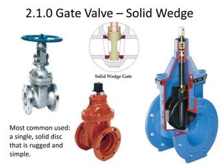
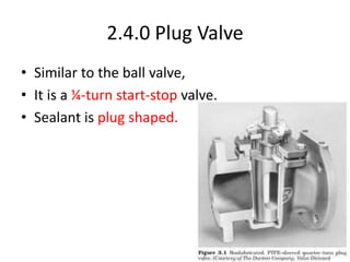
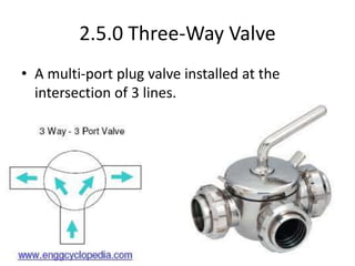
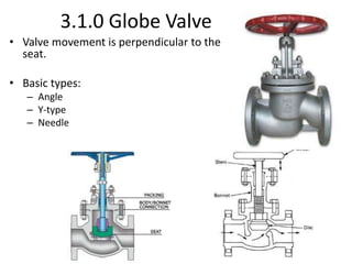
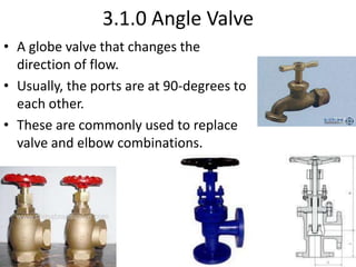
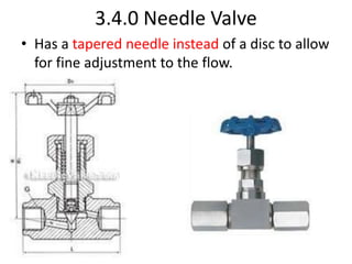
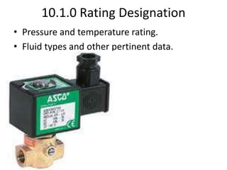
VALVES
1.0.0 Introduction
• Valves are devices that control the flow of
fluids or gases through a piping system.
• Valves are made of a wide variety of materials
for compatibility to the fluid flowing through
it.
2.0.0 Valves That Start and Stop Flow
• These valves are designed to be operated completely
open or completely closed.
• These valves cannot be used effectively to throttle, or
regulate, flow.
• Gate Valve
• Knife Valve
• Ball Valve
• Plug Valve
• Three-Way Valve
2.1.0 Gate Valve
• Turning the hand-wheel lifts or lowers the disc
(gate).
• A partially opened gate causes turbulence.
• This turbulence not only causes piping
damage (water hammer), it also wears the
disc and seat surfaces.
2.1.0 Gate Valve – Solid Wedge
Most common used:
a single, solid disc
that is rugged and
simple.
2.1.0 Gate Valve – Flexible Wedge
A one-piece disc with
a cut or groove
around the edge to
compensate for
irregular sealing
edges.
2.1.0 Gate Valve – Split Wedge
Self-
adjusting
and self-
aligning
discs.
2.1.0 Gate Valve – Double (Parallel) Disc
Prevents valve
binding due to
thermal
transients.
2.1.1 Valve Stem
• Connects the hand-wheel to the gate.
• Rising stem
– Hand-wheel and stem rising when opening
• Non-rising stem
– Hand-wheel and stem do not rise while opening
• Outside screw-&-yoke (OS&Y)
– Stem rises through the hand-wheel while opening
– Stem does not contact the fluid;
• therefore, the OS&Y is suitable for corrosive fluids
2.1.1 Valve Stem
Rising Stem
Non-Rising Stem
OS&Y Stem
2.2.0 Knife Gate Valve
• Gate is thin with tapered edge on the bottom
• Suited for slurry, pulp, waste, and low-
pressure applications
2.3.0 Ball Valve
• Gate is a ball with a hole for flow through it
matching the pipe size
2.4.0 Plug Valve
• Similar to the ball valve,
• It is a ¼-turn start-stop valve.
• Sealant is plug shaped.
2.5.0 Three-Way Valve
• A multi-port plug valve installed at the
intersection of 3 lines.
3.0.0 Valves That Regulate Flow
• These valves can not only start and stop flow,
they can regulate flow.
• The disc can be totally removed from the flow.
• The most common types are:
– Globe Valve
– Butterfly Valve
– Diaphragm Valve
3.1.0 Globe Valve
• Valve movement is perpendicular to the
seat.
• Basic types:
– Angle
– Y-type
– Needle
3.1.0 Angle Valve
• A globe valve that changes the
direction of flow.
• Usually, the ports are at 90-degrees to
each other.
• These are commonly used to replace
valve and elbow combinations.
3.1.0 Y-Type Valve
• Has the straight-through flow of a gate valve.
• Has the throttling and flow control of a globe.
3.1.0 Needle Valve
• Commonly used for precise flow control of
instrumentation applications.
• Not commonly available over 1” in size.
3.2.0 Butterfly Valve
• Has a round disc that turns 90 degrees to
mate with the seat.
• Used in low-to-medium pressures and flows.
3.2.1 Wafer Valve
• Butterfly valve that sandwiches between two
flanges.
3.2.2 Wafer Lug Valve
• Butterfly valve that sandwiches between two
flanges and has lugs to match the bolt holes of
the flange.
3.2.3 Two-Flange Valve
• The body has a flange cast on both sides.
3.3.0 Diaphragm Valve
• Sealing disc is flexible and seals against the body.
• Suitable for slurries, highly corrosive materials,
and materials that cannot be contaminated.
3.4.0 Needle Valve
• Has a tapered needle instead of a disc to allow
for fine adjustment to the flow.
4.0.0 Valves That Relieve Pressure
• Used to control pressure, not flow.
• Two basic types are:
– Safety Valve
– Pressure Relief Valve
4.1.0 Safety Valve
• Used in pipelines and tanks to prevent
ruptures due to excess pressure.
Water
Hydraulic (Sectional View)
Pneumatic
4.2.0 Pressure Relief Valve
• In-line valve to control a specified pressure in the
liquid circuit.
• These usually have the pressure set at the factory.
5.0.0 Valves That Regulate Direction of Flow
• These valves prevent backflow and are
referred to as “check valves”.
• Common types are:
– Swing
– Lift
– Ball
– Butterfly
– Foot
5.1.0 Swing Check Valve
• Uses a hinged disc as the sealing member.
5.2.0 Lift Check Valve
• A one-way-flow check valve that functions like
a globe valve.
5.3.0 Ball Check Valve
• Much like a lift check except that it uses a ball
instead of a disc for sealing.
5.4.0 Butterfly Check Valve
• Two disc hinged in the middle.
5.5.0 Foot Valve
• Used at the bottom of a suction line to
maintain the prime of the pump.
6.0.0 Valve Actuators
• Two primary purposes of valve actuators:
– Provide automatic operation of the valve,
– Reduce the effort required to manually operate the
valve.
• Four basic types of actuators:
– Gear
– Chain
– Pneumatic or Hydraulic
– Motor Driven, Electric or Pneumatic.
6.1.0 Gear Actuators
• Reduces the effort required to manually operate the
valve.
• Three basic types:
• Spur Gear,
• Bevel Gear,
• Worm Gear.
6.1.1 Spur Gear Actuator
• Valve stem and driver shaft are parallel.
6.1.2 Bevel Gear Actuator
• Valve stem and driver shaft are 90 degrees to
each other and the gears are cone-shaped.
6.1.3 Worm Gear Actuator
• Valve stem and driver shaft are 90 degrees to
each other. The driver gear (worm) looks like a
screw.
• Used primarily with butterfly valves.
6.2.0 Chain Actuators
• Reduces the effort required to manually operate the
valve.
• Applicable where the valve is not easily accessible;
such as, too high to reach.
6.3.0 Pneumatic and Hydraulic Actuators
• Uses fluid or air pressure to actuate the valve.
• Most of these are spring-loaded to ensure that
the valve fails in a fail-safe position.
6.4.0 Electric- or Air-Motor Driven Actuators
• Uses motors to actuate the valve.
• Motor can be either electrical or pneumatic.
6.5.0 Control Valves
• Variations of the angle, globe, or ball valves that
are controlled by pneumatic, electronic, or
hydraulic actuators.
• Most commonly used for pressure or
temperature control.
7.0.0 Storing and Handling Valves
• Regardless of the size of the valve, the internal
seats, valves, and springs are precision
machined and must be handled carefully to
avoid damage.
7.1.0 Safety Considerations
• When handling and/or working around valves:
– Be aware of all pinch points,
– Do not stand under a load,
– Be aware of surroundings,
– Never operate a valve in a live system without
authorization,
– Use a spud wrench, not your finger, to align flange
bolt holes.
– Never stand in front of a safety relief valve
discharge.
7.2.0 Storing Valves
• Label all valves.
• Never store valves on the ground.
• Cover all open ends with ‘end protectors’.
7.3.0 Rigging Valves
• Protect all threads and ends.
• Use the proper rigging equipment.
• Connect rigging to body only, not the stem,
handle, or through openings.
• Use a tag line, especially for larger valves.
8.0.0 Installing Valves
• Best working height for manual actuator is
between 2’0” and 4’6” from floor.
• Follow schematics exactly.
– Direction of flow.
– Stem position.
• (vertical up works best, horizontal is acceptable, never
position stem vertical down.)
9.0.0 Valve Selection, Types, and Applications
• Valves can be used in many different
applications.
• Valve selection is important; therefore, follow
design requirements exactly at installation.
9.1.0 Valve Selection
• Important factors:
• Temperature.
• Pressure.
• Pipe size.
• Fluid chemistry.
• Valve function.
10.0.0 Valve Markings and Nameplate Information
• Manufacturers Standardization Society (MSS):
– Developed standards for valve markings.
• American National Standards Institute (ANSI):
• American Society for Testing Materials International (ASTM):
– Both have adopted the MSS marking system.
10.0.0 Valve Markings and Nameplate Information
• Bridgewall markings (globe valves):
– Indicates how the valve seat is angled in relation to the
inlet and outlet ports.
• Flow direction arrow:
– Proper direction of fluid flow.
10.1.0 Rating Designation
• Pressure and temperature rating.
• Fluid types and other pertinent data.
10.2.0 Trim Identification
• Identifies the material of the seat, disc, stem,
and other internal parts if they are different
from the body of the valve.
10.3.0 Size Designation
• Indicates the numerical identification
associated with the pipe size of the
connecting ends.
10.4.0 Thread Markings
• Identifies the size and type of threads for
valves that have threaded connections.
10.5.0 Valve Schematic Symbols
• Valves are shown on schematics by symbols.

Valves.ppt

  • 1.
  • 2.
    1.0.0 Introduction • Valvesare devices that control the flow of fluids or gases through a piping system. • Valves are made of a wide variety of materials for compatibility to the fluid flowing through it.
  • 3.
    2.0.0 Valves ThatStart and Stop Flow • These valves are designed to be operated completely open or completely closed. • These valves cannot be used effectively to throttle, or regulate, flow. • Gate Valve • Knife Valve • Ball Valve • Plug Valve • Three-Way Valve
  • 4.
    2.1.0 Gate Valve •Turning the hand-wheel lifts or lowers the disc (gate). • A partially opened gate causes turbulence. • This turbulence not only causes piping damage (water hammer), it also wears the disc and seat surfaces.
  • 5.
    2.1.0 Gate Valve– Solid Wedge Most common used: a single, solid disc that is rugged and simple.
  • 6.
    2.1.0 Gate Valve– Flexible Wedge A one-piece disc with a cut or groove around the edge to compensate for irregular sealing edges.
  • 7.
    2.1.0 Gate Valve– Split Wedge Self- adjusting and self- aligning discs.
  • 8.
    2.1.0 Gate Valve– Double (Parallel) Disc Prevents valve binding due to thermal transients.
  • 9.
    2.1.1 Valve Stem •Connects the hand-wheel to the gate. • Rising stem – Hand-wheel and stem rising when opening • Non-rising stem – Hand-wheel and stem do not rise while opening • Outside screw-&-yoke (OS&Y) – Stem rises through the hand-wheel while opening – Stem does not contact the fluid; • therefore, the OS&Y is suitable for corrosive fluids
  • 10.
    2.1.1 Valve Stem RisingStem Non-Rising Stem OS&Y Stem
  • 11.
    2.2.0 Knife GateValve • Gate is thin with tapered edge on the bottom • Suited for slurry, pulp, waste, and low- pressure applications
  • 12.
    2.3.0 Ball Valve •Gate is a ball with a hole for flow through it matching the pipe size
  • 13.
    2.4.0 Plug Valve •Similar to the ball valve, • It is a ¼-turn start-stop valve. • Sealant is plug shaped.
  • 14.
    2.5.0 Three-Way Valve •A multi-port plug valve installed at the intersection of 3 lines.
  • 15.
    3.0.0 Valves ThatRegulate Flow • These valves can not only start and stop flow, they can regulate flow. • The disc can be totally removed from the flow. • The most common types are: – Globe Valve – Butterfly Valve – Diaphragm Valve
  • 16.
    3.1.0 Globe Valve •Valve movement is perpendicular to the seat. • Basic types: – Angle – Y-type – Needle
  • 17.
    3.1.0 Angle Valve •A globe valve that changes the direction of flow. • Usually, the ports are at 90-degrees to each other. • These are commonly used to replace valve and elbow combinations.
  • 18.
    3.1.0 Y-Type Valve •Has the straight-through flow of a gate valve. • Has the throttling and flow control of a globe.
  • 19.
    3.1.0 Needle Valve •Commonly used for precise flow control of instrumentation applications. • Not commonly available over 1” in size.
  • 20.
    3.2.0 Butterfly Valve •Has a round disc that turns 90 degrees to mate with the seat. • Used in low-to-medium pressures and flows.
  • 21.
    3.2.1 Wafer Valve •Butterfly valve that sandwiches between two flanges.
  • 22.
    3.2.2 Wafer LugValve • Butterfly valve that sandwiches between two flanges and has lugs to match the bolt holes of the flange.
  • 23.
    3.2.3 Two-Flange Valve •The body has a flange cast on both sides.
  • 24.
    3.3.0 Diaphragm Valve •Sealing disc is flexible and seals against the body. • Suitable for slurries, highly corrosive materials, and materials that cannot be contaminated.
  • 25.
    3.4.0 Needle Valve •Has a tapered needle instead of a disc to allow for fine adjustment to the flow.
  • 26.
    4.0.0 Valves ThatRelieve Pressure • Used to control pressure, not flow. • Two basic types are: – Safety Valve – Pressure Relief Valve
  • 27.
    4.1.0 Safety Valve •Used in pipelines and tanks to prevent ruptures due to excess pressure. Water Hydraulic (Sectional View) Pneumatic
  • 28.
    4.2.0 Pressure ReliefValve • In-line valve to control a specified pressure in the liquid circuit. • These usually have the pressure set at the factory.
  • 29.
    5.0.0 Valves ThatRegulate Direction of Flow • These valves prevent backflow and are referred to as “check valves”. • Common types are: – Swing – Lift – Ball – Butterfly – Foot
  • 30.
    5.1.0 Swing CheckValve • Uses a hinged disc as the sealing member.
  • 31.
    5.2.0 Lift CheckValve • A one-way-flow check valve that functions like a globe valve.
  • 32.
    5.3.0 Ball CheckValve • Much like a lift check except that it uses a ball instead of a disc for sealing.
  • 33.
    5.4.0 Butterfly CheckValve • Two disc hinged in the middle.
  • 34.
    5.5.0 Foot Valve •Used at the bottom of a suction line to maintain the prime of the pump.
  • 35.
    6.0.0 Valve Actuators •Two primary purposes of valve actuators: – Provide automatic operation of the valve, – Reduce the effort required to manually operate the valve. • Four basic types of actuators: – Gear – Chain – Pneumatic or Hydraulic – Motor Driven, Electric or Pneumatic.
  • 36.
    6.1.0 Gear Actuators •Reduces the effort required to manually operate the valve. • Three basic types: • Spur Gear, • Bevel Gear, • Worm Gear.
  • 37.
    6.1.1 Spur GearActuator • Valve stem and driver shaft are parallel.
  • 38.
    6.1.2 Bevel GearActuator • Valve stem and driver shaft are 90 degrees to each other and the gears are cone-shaped.
  • 39.
    6.1.3 Worm GearActuator • Valve stem and driver shaft are 90 degrees to each other. The driver gear (worm) looks like a screw. • Used primarily with butterfly valves.
  • 40.
    6.2.0 Chain Actuators •Reduces the effort required to manually operate the valve. • Applicable where the valve is not easily accessible; such as, too high to reach.
  • 41.
    6.3.0 Pneumatic andHydraulic Actuators • Uses fluid or air pressure to actuate the valve. • Most of these are spring-loaded to ensure that the valve fails in a fail-safe position.
  • 42.
    6.4.0 Electric- orAir-Motor Driven Actuators • Uses motors to actuate the valve. • Motor can be either electrical or pneumatic.
  • 43.
    6.5.0 Control Valves •Variations of the angle, globe, or ball valves that are controlled by pneumatic, electronic, or hydraulic actuators. • Most commonly used for pressure or temperature control.
  • 44.
    7.0.0 Storing andHandling Valves • Regardless of the size of the valve, the internal seats, valves, and springs are precision machined and must be handled carefully to avoid damage.
  • 45.
    7.1.0 Safety Considerations •When handling and/or working around valves: – Be aware of all pinch points, – Do not stand under a load, – Be aware of surroundings, – Never operate a valve in a live system without authorization, – Use a spud wrench, not your finger, to align flange bolt holes. – Never stand in front of a safety relief valve discharge.
  • 46.
    7.2.0 Storing Valves •Label all valves. • Never store valves on the ground. • Cover all open ends with ‘end protectors’.
  • 47.
    7.3.0 Rigging Valves •Protect all threads and ends. • Use the proper rigging equipment. • Connect rigging to body only, not the stem, handle, or through openings. • Use a tag line, especially for larger valves.
  • 48.
    8.0.0 Installing Valves •Best working height for manual actuator is between 2’0” and 4’6” from floor. • Follow schematics exactly. – Direction of flow. – Stem position. • (vertical up works best, horizontal is acceptable, never position stem vertical down.)
  • 49.
    9.0.0 Valve Selection,Types, and Applications • Valves can be used in many different applications. • Valve selection is important; therefore, follow design requirements exactly at installation.
  • 50.
    9.1.0 Valve Selection •Important factors: • Temperature. • Pressure. • Pipe size. • Fluid chemistry. • Valve function.
  • 51.
    10.0.0 Valve Markingsand Nameplate Information • Manufacturers Standardization Society (MSS): – Developed standards for valve markings. • American National Standards Institute (ANSI): • American Society for Testing Materials International (ASTM): – Both have adopted the MSS marking system.
  • 52.
    10.0.0 Valve Markingsand Nameplate Information • Bridgewall markings (globe valves): – Indicates how the valve seat is angled in relation to the inlet and outlet ports. • Flow direction arrow: – Proper direction of fluid flow.
  • 53.
    10.1.0 Rating Designation •Pressure and temperature rating. • Fluid types and other pertinent data.
  • 54.
    10.2.0 Trim Identification •Identifies the material of the seat, disc, stem, and other internal parts if they are different from the body of the valve.
  • 55.
    10.3.0 Size Designation •Indicates the numerical identification associated with the pipe size of the connecting ends.
  • 56.
    10.4.0 Thread Markings •Identifies the size and type of threads for valves that have threaded connections.
  • 57.
    10.5.0 Valve SchematicSymbols • Valves are shown on schematics by symbols.