Download to read offline
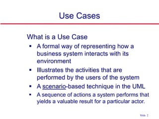
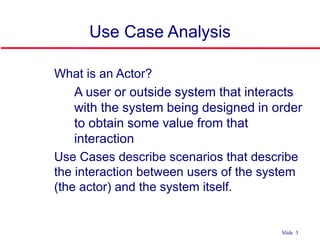
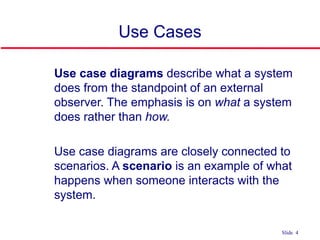

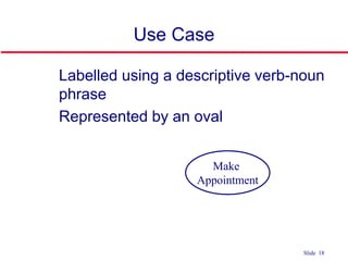
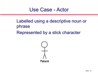
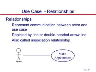
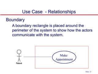
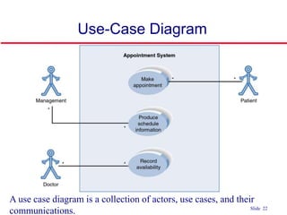
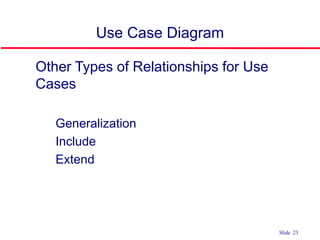
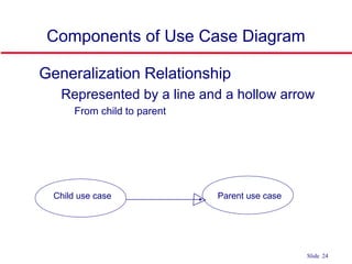
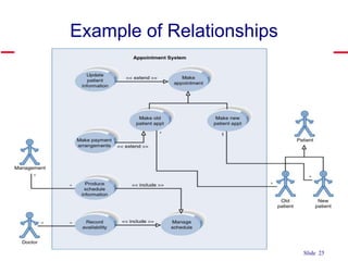
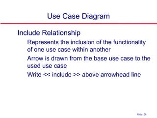
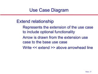


The document discusses use case diagrams as a formal representation of how a business system interacts with its external environment, emphasizing the roles of actors and scenarios. It outlines the components of use cases, including tasks, actors, and their relationships, while providing examples and guidelines for identifying actors and building use case diagrams. Additionally, it addresses the benefits and challenges of using use cases in software engineering.