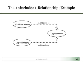
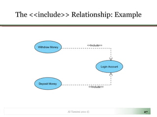
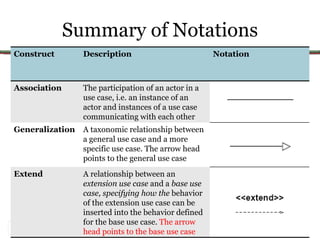
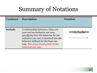
Object Oriented Software Modeling and Design  CE 350 Abdel-Karim Al-Tamimi, Ph.D. [email_address] http://faculty.yu.edu.jo/altamimi Al-Tamimi 2011 ©
Overview Use-case Diagrams Al-Tamimi 2011 ©
Use-Case Diagrams Al-Tamimi 2011 ©
Why We Use Use-case Diagrams Al-Tamimi 2011 ©
Why We Use Use-case Diagrams Answers the main questions about your system: Who’s your system’s for? What must it do? Why build it in the first place? System users:  Actors System normal situations:  use-cases Al-Tamimi 2011 ©
Why We Use Use-case Diagrams Stay focus on your client’s goals A good use case must represent the point of view of the people who will use or interact with the system A complete set of use cases =  system requirements Al-Tamimi 2011 ©
Use-Case Diagram A  use-case model  is a diagram or set of diagrams that together with some additional documentation show what the proposed software system is designed to do. A use-case diagram consists of three main components: Actors  Use-cases , and their communications some additional  documentation  such as use-case descriptions for elaborating use-cases and problem statements that are initially used for identifying use cases Al-Tamimi 2011 ©
Use-Case Diagram: Actors Usually represented with a  stick figure An actor may be: People  Computer hardware and devices External systems Al-Tamimi 2011 ©
Use-Case Diagram: Actors An actor represents a role that a user can play, but  NOT  a specific user Primary actors   are those who use the system’s main functions, deriving benefits from it directly.  Primary actors are completely outside the system and drive the system requirements Primary actors use the system to achieve an observable user goal Secondary actors  play a supporting role to facilitate the primary actors to achieve their goals. Secondary actors often appear to be more  inside  the system than  outside Secondary actors are usually not derived directly from the statement of requirements. Hence, the designer can have more freedom in specifying the roles of these actors Usually found on the right of the system (primary on the left) Al-Tamimi 2011 ©
Use-Case Diagrams: Actors Al-Tamimi 2011 © Actors are treated like classes and thus can be  generalized Student MasterStudent BAStudent
Use-Case Diagrams: Actors and Goals Start by identifying the actors of the system See if the actors can be generalized or not Define the goals of the system and how they can be achieved using the systems’ actors Illustrate these goals and actors actions using use-case diagram(s) Al-Tamimi 2011 ©
Use-case Diagram: Use-case A use case describes a sequence of actions a system performs to yield an  observable result  or  value  to a particular actor  Naming convention = verb + noun (or) verb + noun-phrase,  e.g. withdraw cash A good use case should: Describe a sequence of transactions performed by a system that produces a measurable result (goal) for a particular actor Describe the behavior expected of a system from  a user's perspective Enable the system analyst to understand and model a system from a  high-level business viewpoint Represent the interfaces that a system makes visible to the external entities and the interrelationships between the actors and the system Al-Tamimi 2011 ©
EBP Test for Use-Cases Elementary Business Process (EBP) is a term from the business process engineering field defined as: A task performed by  one person  in  one place  at  one time , in response to a business event, which  adds  a measurable business value and leaves the data in a  consistent state  E.g. Approve Credit or Cancel Order Al-Tamimi 2011 ©
Use-Case Diagram: Use-Case Al-Tamimi 2011 ©
Use-Case Diagram: Example Al-Tamimi 2011 © Actor Association System boundary Use-case System name
Use-Case Diagram: Example Let us consider a simple hotel information system for  two  types of customers:  Tour Group  customers and  Individual customers Tour Group customers are those who have made reservations through a tour operator in advance, while Individual customers make their reservations directly with the hotel  Both types of customers can  book ,  cancel ,  check-in  and  check-out  of a room by  phone  or  via the  Internet Al-Tamimi 2011 ©
Use-Case Diagram: Example Al-Tamimi 2011 ©
Structuring Use-cases with Relationships In the process of developing a use case model, we may discover that some use cases share  common behaviors There are also situations where some use cases are very similar but they have some additional behaviors  For example,  Withdraw Money  and  Deposit Money  both require the user to  log-on  to an ATM system Al-Tamimi 2011 ©
Structuring Use-cases with Relationships Al-Tamimi 2011 © Use Case:  Withdraw Money Flow of Events: . The user inserts an ATM card. The system prompts the user to enter a password. . The user enters the password. The system validates the user password. .... … . … . Use Case:  Deposit Money Flow of Events: . The user inserts an ATM card. The system prompts the user to enter a password. . The user enters the password. The system validates the user password. .... … . … . Common Behavior
Structuring Use-cases with Relationships Al-Tamimi 2011 © Use Case:  Withdraw Money Flow of Events: .  include  ( Login Account ) .... … . … . Use Case:  Deposit Money Flow of Events: .  include  ( Login Account ) … . … . … .. Use Case:  Login Account Flow of Events: . The user inserts an ATM card. The system prompts the user to enter a password. . The user enters the password. The system validates the user password.
The <<include>> Relationship Include relationships are used when two or more use cases share some  common portion in a flow of events  This common portion is then grouped and extracted to form an inclusion use case for sharing among two or more use cases  Most use cases in the ATM system example, such as Withdraw Money, Deposit Money or Check Balance , share the inclusion use-case Login Account  Al-Tamimi 2011 ©
The <<include>> Relationship Al-Tamimi 2011 © Login Account  (Included use case) Withdraw Money  (Base use case)
The <<include>> Relationship When to use include relationship: The behavior of the inclusion use case is common to two or more use cases The  result  of the behavior that the inclusion use case specifies, not the behavior itself, is important to the base use case Al-Tamimi 2011 ©
The <<include>> Relationship: Example Al-Tamimi 2011 ©
The <<extend>> Relationship In UML modeling, you can use an extend relationship to specify that one use case (extension) extends the behavior of another use case (base) This type of relationship reveals details about a system or application that are typically hidden in a use case Al-Tamimi 2011 ©
The <<extend>> Relationship The extend relationship specifies that the incorporation of the extension use case is dependent on what happens when the  base  use case executes The extension use case owns the extend relationship. You can specify several extend relationships for a single base use case Al-Tamimi 2011 ©
The <<extend>> Relationship While the base use case is defined independently and is meaningful by itself, the extension use case  is not meaningful on its own  The extension use case consists of one or several behavior sequences (segments) that describe  additional behavior  that can incrementally augment the behavior of the base use-case  Each segment can be inserted into the base use case at a different point, called  an extension point Al-Tamimi 2011 ©
The <<extend>> Relationship Al-Tamimi 2011 © Process Excess Amount  (Extending use case) Withdraw Money  (Base use case) If conditional guard is true, extending flow is executed
The <<extend>> Relationship The extension use case can access and modify the attributes of the base use case; however, the base use case is not aware of the extension use case and, therefore, cannot access or modify the attributes and operations of the extension use case Al-Tamimi 2011 ©
The <<extend>> Relationship You can add extend relationships to a model to show the following situations: A part of a use case that is optional system behavior A subflow is executed only under certain conditions A set of behavior segments that may be inserted in a base use case Al-Tamimi 2011 ©
The <<extend>> Relationship Al-Tamimi 2011 ©
Al-Tamimi 2011 ©
The Generalization Relationship A  child  use-case can inherit the behaviors, relationships and communication links of a  parent  use-case (like  Actor generalization ) In other words, it is valid to put the child use-case at a place wherever a parent use-case appears The relationship between the child use-case and the parent use-case is the  generalization relationship  For example : suppose the ATM system can be used to pay bills. Pay Bill has two child use cases: Pay Credit Card Bill and Pay Utility Bill
The Generalization Relationship
Use-Case Scope A use case must be initiated by an actor When a use case is considered complete, there are no further inputs or outputs; the desired functionality has been performed, or an error has occurred After a use case has completed, the system is in a state where the use case can be started again, or the system is in an error state
Base Use-Case vs. Abstract Use-Case   Base use case – invoked directly by actor to achieve an observable goal Abstract use case – invoked by other use cases and is not a complete goal from user’s perspective  e.g. withdraw cash (concrete use case) vs. login (abstract use case)
Use-Case Scope
Use-Case Scope
Summary of Notations Construct  Description Notation Use-case A sequence of transactions performed by a system that produces a measurable result for a particular actor Actor A coherent set of roles that users play when interacting with these use cases System Boundary The boundary between the physical system and the actors who interact with the physical system
Summary of Notations Construct  Description Notation Association The participation of an actor in a use case, i.e. an instance of an actor and instances of a use case communicating with each other Generalization A taxonomic relationship between a general use case and a more specific use case. The arrow head points to the general use case Extend A relationship between an  extension use case  and a  base use case, specifying how the  behavior of the extension use case can be inserted into the behavior defined for the base use case.  The arrow head points to the base use case
Summary of Notations Construct  Description Notation Include A relationship between a  base use case and  an  inclusion use case, specifying how the  behavior for the inclusion use case is inserted into the behavior defined for the base use case.  The arrow head points to the inclusion use case
Resources Chapter 3 from  “Object-Oriented Technology: From diagram to code with Visual Paradigm for UML” UML 2 for dummies, chapters 8-10 UML 2 certification guide, chapter 2 Chapter 6 from “Applying UML and Patterns” Al-Tamimi 2011 ©

Lecture04- Use Case Diagrams

  • 1.
    Object Oriented SoftwareModeling and Design CE 350 Abdel-Karim Al-Tamimi, Ph.D. [email_address] http://faculty.yu.edu.jo/altamimi Al-Tamimi 2011 ©
  • 2.
    Overview Use-case DiagramsAl-Tamimi 2011 ©
  • 3.
  • 4.
    Why We UseUse-case Diagrams Al-Tamimi 2011 ©
  • 5.
    Why We UseUse-case Diagrams Answers the main questions about your system: Who’s your system’s for? What must it do? Why build it in the first place? System users: Actors System normal situations: use-cases Al-Tamimi 2011 ©
  • 6.
    Why We UseUse-case Diagrams Stay focus on your client’s goals A good use case must represent the point of view of the people who will use or interact with the system A complete set of use cases = system requirements Al-Tamimi 2011 ©
  • 7.
    Use-Case Diagram A use-case model is a diagram or set of diagrams that together with some additional documentation show what the proposed software system is designed to do. A use-case diagram consists of three main components: Actors Use-cases , and their communications some additional documentation such as use-case descriptions for elaborating use-cases and problem statements that are initially used for identifying use cases Al-Tamimi 2011 ©
  • 8.
    Use-Case Diagram: ActorsUsually represented with a stick figure An actor may be: People Computer hardware and devices External systems Al-Tamimi 2011 ©
  • 9.
    Use-Case Diagram: ActorsAn actor represents a role that a user can play, but NOT a specific user Primary actors are those who use the system’s main functions, deriving benefits from it directly. Primary actors are completely outside the system and drive the system requirements Primary actors use the system to achieve an observable user goal Secondary actors play a supporting role to facilitate the primary actors to achieve their goals. Secondary actors often appear to be more inside the system than outside Secondary actors are usually not derived directly from the statement of requirements. Hence, the designer can have more freedom in specifying the roles of these actors Usually found on the right of the system (primary on the left) Al-Tamimi 2011 ©
  • 10.
    Use-Case Diagrams: ActorsAl-Tamimi 2011 © Actors are treated like classes and thus can be generalized Student MasterStudent BAStudent
  • 11.
    Use-Case Diagrams: Actorsand Goals Start by identifying the actors of the system See if the actors can be generalized or not Define the goals of the system and how they can be achieved using the systems’ actors Illustrate these goals and actors actions using use-case diagram(s) Al-Tamimi 2011 ©
  • 12.
    Use-case Diagram: Use-caseA use case describes a sequence of actions a system performs to yield an observable result or value to a particular actor Naming convention = verb + noun (or) verb + noun-phrase, e.g. withdraw cash A good use case should: Describe a sequence of transactions performed by a system that produces a measurable result (goal) for a particular actor Describe the behavior expected of a system from a user's perspective Enable the system analyst to understand and model a system from a high-level business viewpoint Represent the interfaces that a system makes visible to the external entities and the interrelationships between the actors and the system Al-Tamimi 2011 ©
  • 13.
    EBP Test forUse-Cases Elementary Business Process (EBP) is a term from the business process engineering field defined as: A task performed by one person in one place at one time , in response to a business event, which adds a measurable business value and leaves the data in a consistent state E.g. Approve Credit or Cancel Order Al-Tamimi 2011 ©
  • 14.
    Use-Case Diagram: Use-CaseAl-Tamimi 2011 ©
  • 15.
    Use-Case Diagram: Use-CaseAl-Tamimi 2011 ©
  • 16.
    Use-Case Diagram: Use-CaseAl-Tamimi 2011 ©
  • 17.
    Use-Case Diagram: ExampleAl-Tamimi 2011 © Actor Association System boundary Use-case System name
  • 18.
    Use-Case Diagram: ExampleLet us consider a simple hotel information system for two types of customers: Tour Group customers and Individual customers Tour Group customers are those who have made reservations through a tour operator in advance, while Individual customers make their reservations directly with the hotel Both types of customers can book , cancel , check-in and check-out of a room by phone or via the Internet Al-Tamimi 2011 ©
  • 19.
    Use-Case Diagram: ExampleAl-Tamimi 2011 ©
  • 20.
    Structuring Use-cases withRelationships In the process of developing a use case model, we may discover that some use cases share common behaviors There are also situations where some use cases are very similar but they have some additional behaviors For example, Withdraw Money and Deposit Money both require the user to log-on to an ATM system Al-Tamimi 2011 ©
  • 21.
    Structuring Use-cases withRelationships Al-Tamimi 2011 © Use Case: Withdraw Money Flow of Events: . The user inserts an ATM card. The system prompts the user to enter a password. . The user enters the password. The system validates the user password. .... … . … . Use Case: Deposit Money Flow of Events: . The user inserts an ATM card. The system prompts the user to enter a password. . The user enters the password. The system validates the user password. .... … . … . Common Behavior
  • 22.
    Structuring Use-cases withRelationships Al-Tamimi 2011 © Use Case: Withdraw Money Flow of Events: . include ( Login Account ) .... … . … . Use Case: Deposit Money Flow of Events: . include ( Login Account ) … . … . … .. Use Case: Login Account Flow of Events: . The user inserts an ATM card. The system prompts the user to enter a password. . The user enters the password. The system validates the user password.
  • 23.
    The <<include>> RelationshipInclude relationships are used when two or more use cases share some common portion in a flow of events This common portion is then grouped and extracted to form an inclusion use case for sharing among two or more use cases Most use cases in the ATM system example, such as Withdraw Money, Deposit Money or Check Balance , share the inclusion use-case Login Account Al-Tamimi 2011 ©
  • 24.
    The <<include>> RelationshipAl-Tamimi 2011 © Login Account (Included use case) Withdraw Money (Base use case)
  • 25.
    The <<include>> RelationshipWhen to use include relationship: The behavior of the inclusion use case is common to two or more use cases The result of the behavior that the inclusion use case specifies, not the behavior itself, is important to the base use case Al-Tamimi 2011 ©
  • 26.
    The <<include>> Relationship:Example Al-Tamimi 2011 ©
  • 27.
    The <<include>> Relationship:Example Al-Tamimi 2011 ©
  • 28.
    The <<extend>> RelationshipIn UML modeling, you can use an extend relationship to specify that one use case (extension) extends the behavior of another use case (base) This type of relationship reveals details about a system or application that are typically hidden in a use case Al-Tamimi 2011 ©
  • 29.
    The <<extend>> RelationshipThe extend relationship specifies that the incorporation of the extension use case is dependent on what happens when the base use case executes The extension use case owns the extend relationship. You can specify several extend relationships for a single base use case Al-Tamimi 2011 ©
  • 30.
    The <<extend>> RelationshipWhile the base use case is defined independently and is meaningful by itself, the extension use case is not meaningful on its own The extension use case consists of one or several behavior sequences (segments) that describe additional behavior that can incrementally augment the behavior of the base use-case Each segment can be inserted into the base use case at a different point, called an extension point Al-Tamimi 2011 ©
  • 31.
    The <<extend>> RelationshipAl-Tamimi 2011 © Process Excess Amount (Extending use case) Withdraw Money (Base use case) If conditional guard is true, extending flow is executed
  • 32.
    The <<extend>> RelationshipThe extension use case can access and modify the attributes of the base use case; however, the base use case is not aware of the extension use case and, therefore, cannot access or modify the attributes and operations of the extension use case Al-Tamimi 2011 ©
  • 33.
    The <<extend>> RelationshipYou can add extend relationships to a model to show the following situations: A part of a use case that is optional system behavior A subflow is executed only under certain conditions A set of behavior segments that may be inserted in a base use case Al-Tamimi 2011 ©
  • 34.
    The <<extend>> RelationshipAl-Tamimi 2011 ©
  • 35.
    The <<extend>> RelationshipAl-Tamimi 2011 ©
  • 36.
    The <<extend>> RelationshipAl-Tamimi 2011 ©
  • 37.
  • 38.
    The Generalization RelationshipA child use-case can inherit the behaviors, relationships and communication links of a parent use-case (like Actor generalization ) In other words, it is valid to put the child use-case at a place wherever a parent use-case appears The relationship between the child use-case and the parent use-case is the generalization relationship For example : suppose the ATM system can be used to pay bills. Pay Bill has two child use cases: Pay Credit Card Bill and Pay Utility Bill
  • 39.
  • 40.
  • 41.
    Use-Case Scope Ause case must be initiated by an actor When a use case is considered complete, there are no further inputs or outputs; the desired functionality has been performed, or an error has occurred After a use case has completed, the system is in a state where the use case can be started again, or the system is in an error state
  • 42.
    Base Use-Case vs.Abstract Use-Case Base use case – invoked directly by actor to achieve an observable goal Abstract use case – invoked by other use cases and is not a complete goal from user’s perspective e.g. withdraw cash (concrete use case) vs. login (abstract use case)
  • 43.
  • 44.
  • 45.
    Summary of NotationsConstruct Description Notation Use-case A sequence of transactions performed by a system that produces a measurable result for a particular actor Actor A coherent set of roles that users play when interacting with these use cases System Boundary The boundary between the physical system and the actors who interact with the physical system
  • 46.
    Summary of NotationsConstruct Description Notation Association The participation of an actor in a use case, i.e. an instance of an actor and instances of a use case communicating with each other Generalization A taxonomic relationship between a general use case and a more specific use case. The arrow head points to the general use case Extend A relationship between an extension use case and a base use case, specifying how the behavior of the extension use case can be inserted into the behavior defined for the base use case. The arrow head points to the base use case
  • 47.
    Summary of NotationsConstruct Description Notation Include A relationship between a base use case and an inclusion use case, specifying how the behavior for the inclusion use case is inserted into the behavior defined for the base use case. The arrow head points to the inclusion use case
  • 48.
    Resources Chapter 3from “Object-Oriented Technology: From diagram to code with Visual Paradigm for UML” UML 2 for dummies, chapters 8-10 UML 2 certification guide, chapter 2 Chapter 6 from “Applying UML and Patterns” Al-Tamimi 2011 ©