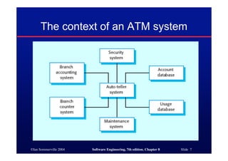
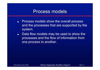
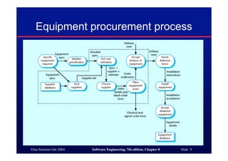
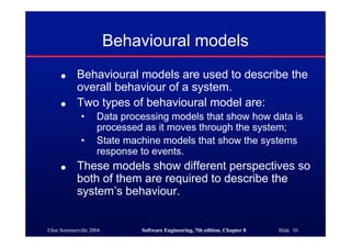
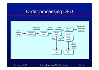
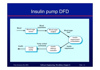
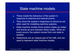
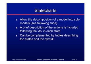
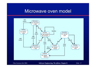
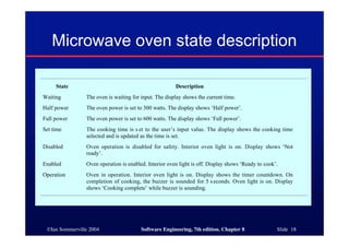
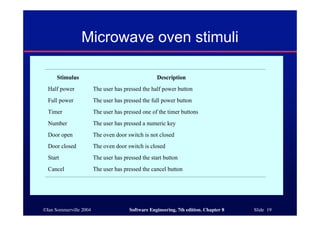
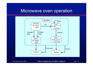
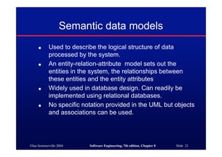
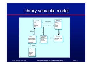
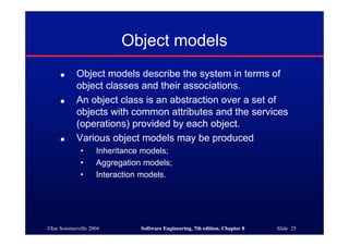
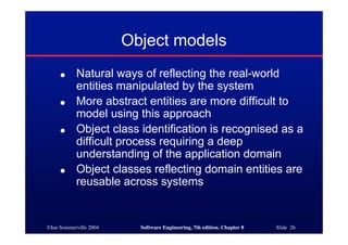
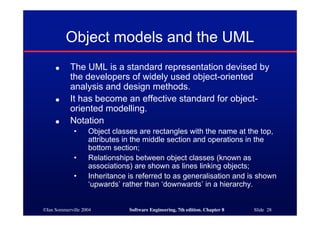
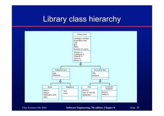
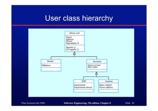
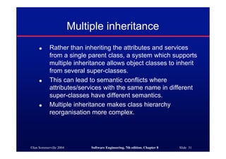
SlideShare a Scribd company logo
©Ian Sommerville 2004 Software Engineering, 7th edition. Chapter 8 Slide 1
System models
©Ian Sommerville 2004 Software Engineering, 7th edition. Chapter 8 Slide 2
Objectives
● To explain why the context of a system
should be modelled as part of the RE
process
● To describe behavioural modelling, data
modelling and object modelling
● To introduce some of the notations used in
the Unified Modeling Language (UML)
● To show how CASE workbenches support
system modelling
©Ian Sommerville 2004 Software Engineering, 7th edition. Chapter 8 Slide 3
Topics covered
● Context models
● Behavioural models
● Data models
● Object models
● CASE workbenches
©Ian Sommerville 2004 Software Engineering, 7th edition. Chapter 8 Slide 4
System modelling
● System modelling helps the analyst to understand
the functionality of the system and models are used
to communicate with customers.
● Different models present the system from different
perspectives
• External perspective showing the system’s context or
environment;
• Behavioural perspective showing the behaviour of the
system;
• Structural perspective showing the system or data
architecture.
©Ian Sommerville 2004 Software Engineering, 7th edition. Chapter 8 Slide 5
Model types
● Data processing model showing how the data is
processed at different stages.
● Composition model showing how entities are
composed of other entities.
● Architectural model showing principal sub-systems.
● Classification model showing how entities have
common characteristics.
● Stimulus/response model showing the system’s
reaction to events.
©Ian Sommerville 2004 Software Engineering, 7th edition. Chapter 8 Slide 6
Context models
● Context models are used to illustrate the
operational context of a system - they show
what lies outside the system boundaries.
● Social and organisational concerns may
affect the decision on where to position
system boundaries.
● Architectural models show the system and its
relationship with other systems.
©Ian Sommerville 2004 Software Engineering, 7th edition. Chapter 8 Slide 7
The context of an ATM system
©Ian Sommerville 2004 Software Engineering, 7th edition. Chapter 8 Slide 8
Process models
● Process models show the overall process
and the processes that are supported by the
system.
● Data flow models may be used to show the
processes and the flow of information from
one process to another.
©Ian Sommerville 2004 Software Engineering, 7th edition. Chapter 8 Slide 9
Equipment procurement process
©Ian Sommerville 2004 Software Engineering, 7th edition. Chapter 8 Slide 10
Behavioural models
● Behavioural models are used to describe the
overall behaviour of a system.
● Two types of behavioural model are:
• Data processing models that show how data is
processed as it moves through the system;
• State machine models that show the systems
response to events.
● These models show different perspectives so
both of them are required to describe the
system’s behaviour.
©Ian Sommerville 2004 Software Engineering, 7th edition. Chapter 8 Slide 11
Data-processing models
● Data flow diagrams (DFDs) may be used to
model the system’s data processing.
● These show the processing steps as data
flows through a system.
● DFDs are an intrinsic part of many analysis
methods.
● Simple and intuitive notation that customers
can understand.
● Show end-to-end processing of data.
©Ian Sommerville 2004 Software Engineering, 7th edition. Chapter 8 Slide 12
Order processing DFD
©Ian Sommerville 2004 Software Engineering, 7th edition. Chapter 8 Slide 13
Data flow diagrams
● DFDs model the system from a functional
perspective.
● Tracking and documenting how the data
associated with a process is helpful to
develop an overall understanding of the
system.
● Data flow diagrams may also be used in
showing the data exchange between a
system and other systems in its environment.
©Ian Sommerville 2004 Software Engineering, 7th edition. Chapter 8 Slide 14
Insulin pump DFD
©Ian Sommerville 2004 Software Engineering, 7th edition. Chapter 8 Slide 15
State machine models
● These model the behaviour of the system in
response to external and internal events.
● They show the system’s responses to stimuli so are
often used for modelling real-time systems.
● State machine models show system states as nodes
and events as arcs between these nodes. When an
event occurs, the system moves from one state to
another.
● Statecharts are an integral part of the UML and are
used to represent state machine models.
©Ian Sommerville 2004 Software Engineering, 7th edition. Chapter 8 Slide 16
Statecharts
● Allow the decomposition of a model into sub-
models (see following slide).
● A brief description of the actions is included
following the ‘do’ in each state.
● Can be complemented by tables describing
the states and the stimuli.
©Ian Sommerville 2004 Software Engineering, 7th edition. Chapter 8 Slide 17
Microwave oven model
©Ian Sommerville 2004 Software Engineering, 7th edition. Chapter 8 Slide 18
Microwave oven state description
State Description
Waiting The oven is waiting for input. The display shows the current time.
Half power The oven power is set to 300 watts. The display shows ‘Half power’.
Full power The oven power is set to 600 watts. The display shows ‘Full power’.
Set time The cooking time is s et to the user’s input value. The display shows the cooking time
selected and is updated as the time is set.
Disabled Oven operation is disabled for safety. Interior oven light is on. Display shows ‘Not
ready’.
Enabled Oven operation is enabled. Interior oven light is off. Display shows ‘Ready to cook’.
Operation Oven in operation. Interior oven light is on. Display shows the timer countdown. On
completion of cooking, the buzzer is sounded for 5 s econds. Oven light is on. Display
shows ‘Cooking complete’ while buzzer is sounding.
©Ian Sommerville 2004 Software Engineering, 7th edition. Chapter 8 Slide 19
Microwave oven stimuli
Stimulus Description
Half power The user has pressed the half power button
Full power The user has pressed the full power button
Timer The user has pressed one of the timer buttons
Number The user has pressed a numeric key
Door open The oven door switch is not closed
Door closed The oven door switch is closed
Start The user has pressed the start button
Cancel The user has pressed the cancel button
©Ian Sommerville 2004 Software Engineering, 7th edition. Chapter 8 Slide 20
Microwave oven operation
©Ian Sommerville 2004 Software Engineering, 7th edition. Chapter 8 Slide 21
Semantic data models
● Used to describe the logical structure of data
processed by the system.
● An entity-relation-attribute model sets out the
entities in the system, the relationships between
these entities and the entity attributes
● Widely used in database design. Can readily be
implemented using relational databases.
● No specific notation provided in the UML but objects
and associations can be used.
©Ian Sommerville 2004 Software Engineering, 7th edition. Chapter 8 Slide 22
Library semantic model
©Ian Sommerville 2004 Software Engineering, 7th edition. Chapter 8 Slide 23
Data dictionaries
● Data dictionaries are lists of all of the names used in
the system models. Descriptions of the entities,
relationships and attributes are also included.
● Advantages
• Support name management and avoid duplication;
• Store of organisational knowledge linking analysis, design
and implementation;
● Many CASE workbenches support data dictionaries.
©Ian Sommerville 2004 Software Engineering, 7th edition. Chapter 8 Slide 24
Data dictionary entries
Name Description Type Date
Article
Details of the published article that may be ordered by
people using LIBSYS.
Entity 30.12.2002
authors
The names of the authors of the article who may be due
a share of the fee.
Attribute 30.12.2002
Buyer
The person or organisation that orders a co py of the
article.
Entity 30.12.2002
fee-
payable-to
A 1:1 relationship between Article and the Copyright
Agency who should be paid the copyright fee.
Relation 29.12.2002
Address
(Buyer)
The address of the buyer. This is used to any paper
billing information that is required.
Attribute 31.12.2002
©Ian Sommerville 2004 Software Engineering, 7th edition. Chapter 8 Slide 25
Object models
● Object models describe the system in terms of
object classes and their associations.
● An object class is an abstraction over a set of
objects with common attributes and the services
(operations) provided by each object.
● Various object models may be produced
• Inheritance models;
• Aggregation models;
• Interaction models.
©Ian Sommerville 2004 Software Engineering, 7th edition. Chapter 8 Slide 26
Object models
● Natural ways of reflecting the real-world
entities manipulated by the system
● More abstract entities are more difficult to
model using this approach
● Object class identification is recognised as a
difficult process requiring a deep
understanding of the application domain
● Object classes reflecting domain entities are
reusable across systems
©Ian Sommerville 2004 Software Engineering, 7th edition. Chapter 8 Slide 27
Inheritance models
● Organise the domain object classes into a hierarchy.
● Classes at the top of the hierarchy reflect the
common features of all classes.
● Object classes inherit their attributes and services
from one or more super-classes. these may then be
specialised as necessary.
● Class hierarchy design can be a difficult process if
duplication in different branches is to be avoided.
©Ian Sommerville 2004 Software Engineering, 7th edition. Chapter 8 Slide 28
Object models and the UML
● The UML is a standard representation devised by
the developers of widely used object-oriented
analysis and design methods.
● It has become an effective standard for object-
oriented modelling.
● Notation
• Object classes are rectangles with the name at the top,
attributes in the middle section and operations in the
bottom section;
• Relationships between object classes (known as
associations) are shown as lines linking objects;
• Inheritance is referred to as generalisation and is shown
‘upwards’ rather than ‘downwards’ in a hierarchy.
©Ian Sommerville 2004 Software Engineering, 7th edition. Chapter 8 Slide 29
Library class hierarchy
©Ian Sommerville 2004 Software Engineering, 7th edition. Chapter 8 Slide 30
User class hierarchy
©Ian Sommerville 2004 Software Engineering, 7th edition. Chapter 8 Slide 31
Multiple inheritance
● Rather than inheriting the attributes and services
from a single parent class, a system which supports
multiple inheritance allows object classes to inherit
from several super-classes.
● This can lead to semantic conflicts where
attributes/services with the same name in different
super-classes have different semantics.
● Multiple inheritance makes class hierarchy
reorganisation more complex.
©Ian Sommerville 2004 Software Engineering, 7th edition. Chapter 8 Slide 32
Multiple inheritance
©Ian Sommerville 2004 Software Engineering, 7th edition. Chapter 8 Slide 33
Object aggregation
● An aggregation model shows how classes
that are collections are composed of other
classes.
● Aggregation models are similar to the part-of
relationship in semantic data models.
©Ian Sommerville 2004 Software Engineering, 7th edition. Chapter 8 Slide 34
Object aggregation
©Ian Sommerville 2004 Software Engineering, 7th edition. Chapter 8 Slide 35
Object behaviour modelling
● A behavioural model shows the interactions
between objects to produce some particular
system behaviour that is specified as a use-
case.
● Sequence diagrams (or collaboration
diagrams) in the UML are used to model
interaction between objects.
©Ian Sommerville 2004 Software Engineering, 7th edition. Chapter 8 Slide 36
Issue of electronic items
©Ian Sommerville 2004 Software Engineering, 7th edition. Chapter 8 Slide 37
Structured methods
● Structured methods incorporate system
modelling as an inherent part of the method.
● Methods define a set of models, a process
for deriving these models and rules and
guidelines that should apply to the models.
● CASE tools support system modelling as
part of a structured method.
©Ian Sommerville 2004 Software Engineering, 7th edition. Chapter 8 Slide 38
Method weaknesses
● They do not model non-functional system
requirements.
● They do not usually include information
about whether a method is appropriate for a
given problem.
● The may produce too much documentation.
● The system models are sometimes too
detailed and difficult for users to understand.
©Ian Sommerville 2004 Software Engineering, 7th edition. Chapter 8 Slide 39
CASE workbenches
● A coherent set of tools that is designed to
support related software process activities
such as analysis, design or testing.
● Analysis and design workbenches support
system modelling during both requirements
engineering and system design.
● These workbenches may support a specific
design method or may provide support for a
creating several different types of system
model.
©Ian Sommerville 2004 Software Engineering, 7th edition. Chapter 8 Slide 40
An analysis and design workbench
©Ian Sommerville 2004 Software Engineering, 7th edition. Chapter 8 Slide 41
Analysis workbench components
● Diagram editors
● Model analysis and checking tools
● Repository and associated query language
● Data dictionary
● Report definition and generation tools
● Forms definition tools
● Import/export translators
● Code generation tools
©Ian Sommerville 2004 Software Engineering, 7th edition. Chapter 8 Slide 42
Key points
● A model is an abstract system view.
Complementary types of model provide
different system information.
● Context models show the position of a
system in its environment with other systems
and processes.
● Data flow models may be used to model the
data processing in a system.
● State machine models model the system’s
behaviour in response to internal or external
events
©Ian Sommerville 2004 Software Engineering, 7th edition. Chapter 8 Slide 43
Key points
● Semantic data models describe the logical
structure of data which is imported to or
exported by the systems.
● Object models describe logical system
entities, their classification and aggregation.
● Sequence models show the interactions
between actors and the system objects that
they use.
● Structured methods provide a framework for
developing system models.

More Related Content

What's hot

Dead Lock in operating system
Dead Lock in operating systemDead Lock in operating system
Dead Lock in operating system
Ali Haider
 
Uml class-diagram
Uml class-diagramUml class-diagram
Uml class-diagram
ASHOK KUMAR PALAKI
 
Services provided by os
Services provided by osServices provided by os
Services provided by os
Sumant Diwakar
 
Software Verification & Validation
Software Verification & ValidationSoftware Verification & Validation
Software Verification & Validation
university of education,Lahore
 
Uml with detail
Uml with detailUml with detail
Uml with detail
Hamza Khan
 
Process of operating system
Process of operating systemProcess of operating system
Object oriented methodologies
Object oriented methodologiesObject oriented methodologies
Object oriented methodologies
naina-rani
 
Memory Management in OS
Memory Management in OSMemory Management in OS
Memory Management in OS
Kumar Pritam
 
Use case diagram
Use case diagramUse case diagram
Use case diagram
City University
 
Reusibility vs Extensibility in OOAD
Reusibility vs Extensibility in OOADReusibility vs Extensibility in OOAD
Reusibility vs Extensibility in OOAD
Shivani Kapoor
 
Corba concepts & corba architecture
Corba concepts & corba architectureCorba concepts & corba architecture
Corba concepts & corba architecture
nupurmakhija1211
 
Unit Testing (C#)
Unit Testing (C#)Unit Testing (C#)
Unit Testing (C#)
Prashant Cholachagudd
 
Object oriented analysis &design - requirement analysis
Object oriented analysis &design - requirement analysisObject oriented analysis &design - requirement analysis
Object oriented analysis &design - requirement analysis
Abhilasha Lahigude
 
Test case techniques
Test case techniquesTest case techniques
Test case techniques
Pina Parmar
 
Verification and Validation in Software Engineering SE19
Verification and Validation in Software Engineering SE19Verification and Validation in Software Engineering SE19
Verification and Validation in Software Engineering SE19
koolkampus
 
Debugging
DebuggingDebugging
Black box and white box testing
Black box and white box testingBlack box and white box testing
Black box and white box testing
AWADHESH PRATAP SINGH UNIVERSITY, REWA (M.P.)
 
White box testing
White box testingWhite box testing
White box testing
Neethu Tressa
 
Requirement engineering process
Requirement engineering processRequirement engineering process
Requirement engineering process
Dr. Loganathan R
 
UML
UMLUML

What's hot (20)

Dead Lock in operating system
Dead Lock in operating systemDead Lock in operating system
Dead Lock in operating system
 
Uml class-diagram
Uml class-diagramUml class-diagram
Uml class-diagram
 
Services provided by os
Services provided by osServices provided by os
Services provided by os
 
Software Verification & Validation
Software Verification & ValidationSoftware Verification & Validation
Software Verification & Validation
 
Uml with detail
Uml with detailUml with detail
Uml with detail
 
Process of operating system
Process of operating systemProcess of operating system
Process of operating system
 
Object oriented methodologies
Object oriented methodologiesObject oriented methodologies
Object oriented methodologies
 
Memory Management in OS
Memory Management in OSMemory Management in OS
Memory Management in OS
 
Use case diagram
Use case diagramUse case diagram
Use case diagram
 
Reusibility vs Extensibility in OOAD
Reusibility vs Extensibility in OOADReusibility vs Extensibility in OOAD
Reusibility vs Extensibility in OOAD
 
Corba concepts & corba architecture
Corba concepts & corba architectureCorba concepts & corba architecture
Corba concepts & corba architecture
 
Unit Testing (C#)
Unit Testing (C#)Unit Testing (C#)
Unit Testing (C#)
 
Object oriented analysis &design - requirement analysis
Object oriented analysis &design - requirement analysisObject oriented analysis &design - requirement analysis
Object oriented analysis &design - requirement analysis
 
Test case techniques
Test case techniquesTest case techniques
Test case techniques
 
Verification and Validation in Software Engineering SE19
Verification and Validation in Software Engineering SE19Verification and Validation in Software Engineering SE19
Verification and Validation in Software Engineering SE19
 
Debugging
DebuggingDebugging
Debugging
 
Black box and white box testing
Black box and white box testingBlack box and white box testing
Black box and white box testing
 
White box testing
White box testingWhite box testing
White box testing
 
Requirement engineering process
Requirement engineering processRequirement engineering process
Requirement engineering process
 
UML
UMLUML
UML
 

Similar to System Modelling

ch07.ppt
ch07.pptch07.ppt
ch07.ppt
AbdulraufKhan29
 
Systemmodels
SystemmodelsSystemmodels
Systemmodels
sietk
 
Software Engineering - Ch11
Software Engineering - Ch11Software Engineering - Ch11
Software Engineering - Ch11
Siddharth Ayer
 
Week 5
Week 5Week 5
SELECT21.pptx
SELECT21.pptxSELECT21.pptx
SELECT21.pptx
devnasra1
 
Ch11
Ch11Ch11
Ch11
phanleson
 
Architectural Design Software Engineering 7th Edition
Architectural Design Software Engineering 7th EditionArchitectural Design Software Engineering 7th Edition
Architectural Design Software Engineering 7th Edition
chess188chess188
 
Architectural Design Software Engineering 7th Edition
Architectural Design Software Engineering 7th EditionArchitectural Design Software Engineering 7th Edition
Architectural Design Software Engineering 7th Edition
chess188chess188
 
Ch14
Ch14Ch14
Workshop on Basics of Software Engineering (DFD, UML and Project Culture)
Workshop on Basics of Software Engineering (DFD, UML and Project Culture)Workshop on Basics of Software Engineering (DFD, UML and Project Culture)
Workshop on Basics of Software Engineering (DFD, UML and Project Culture)
Dr Sukhpal Singh Gill
 
analysis and design with uml
analysis and design with umlanalysis and design with uml
analysis and design with uml
sabin kafle
 
Unit 3 system models
Unit 3 system modelsUnit 3 system models
Unit 3 system models
Azhar Shaik
 
8 system models (1)
8 system models (1)8 system models (1)
8 system models (1)
Ayesha Bhatti
 
8 system models
8 system models8 system models
8 system models
Ayesha Bhatti
 
07 - Design and Implementation.pptx
07 - Design and Implementation.pptx07 - Design and Implementation.pptx
07 - Design and Implementation.pptx
ssuser13a155
 
Ch7-Software Engineering 9
Ch7-Software Engineering 9Ch7-Software Engineering 9
Ch7-Software Engineering 9
Ian Sommerville
 
IRJET- Use of Simulation in Different Phases of Manufacturing System Life Cycle
IRJET- Use of Simulation in Different Phases of Manufacturing System Life CycleIRJET- Use of Simulation in Different Phases of Manufacturing System Life Cycle
IRJET- Use of Simulation in Different Phases of Manufacturing System Life Cycle
IRJET Journal
 
07. MTE - Studi Kasus Pemodelan Sistem.pptx
07. MTE - Studi Kasus Pemodelan Sistem.pptx07. MTE - Studi Kasus Pemodelan Sistem.pptx
07. MTE - Studi Kasus Pemodelan Sistem.pptx
AsalReview
 
Software Engineering-Unit 3 "System Modelling" by Adi.pdf
Software Engineering-Unit 3 "System Modelling" by Adi.pdfSoftware Engineering-Unit 3 "System Modelling" by Adi.pdf
Software Engineering-Unit 3 "System Modelling" by Adi.pdf
Prof. Dr. K. Adisesha
 
Unified Modeling Language (UML)
Unified Modeling Language (UML)Unified Modeling Language (UML)
Unified Modeling Language (UML)
Ajeng Savitri
 

Similar to System Modelling (20)

ch07.ppt
ch07.pptch07.ppt
ch07.ppt
 
Systemmodels
SystemmodelsSystemmodels
Systemmodels
 
Software Engineering - Ch11
Software Engineering - Ch11Software Engineering - Ch11
Software Engineering - Ch11
 
Week 5
Week 5Week 5
Week 5
 
SELECT21.pptx
SELECT21.pptxSELECT21.pptx
SELECT21.pptx
 
Ch11
Ch11Ch11
Ch11
 
Architectural Design Software Engineering 7th Edition
Architectural Design Software Engineering 7th EditionArchitectural Design Software Engineering 7th Edition
Architectural Design Software Engineering 7th Edition
 
Architectural Design Software Engineering 7th Edition
Architectural Design Software Engineering 7th EditionArchitectural Design Software Engineering 7th Edition
Architectural Design Software Engineering 7th Edition
 
Ch14
Ch14Ch14
Ch14
 
Workshop on Basics of Software Engineering (DFD, UML and Project Culture)
Workshop on Basics of Software Engineering (DFD, UML and Project Culture)Workshop on Basics of Software Engineering (DFD, UML and Project Culture)
Workshop on Basics of Software Engineering (DFD, UML and Project Culture)
 
analysis and design with uml
analysis and design with umlanalysis and design with uml
analysis and design with uml
 
Unit 3 system models
Unit 3 system modelsUnit 3 system models
Unit 3 system models
 
8 system models (1)
8 system models (1)8 system models (1)
8 system models (1)
 
8 system models
8 system models8 system models
8 system models
 
07 - Design and Implementation.pptx
07 - Design and Implementation.pptx07 - Design and Implementation.pptx
07 - Design and Implementation.pptx
 
Ch7-Software Engineering 9
Ch7-Software Engineering 9Ch7-Software Engineering 9
Ch7-Software Engineering 9
 
IRJET- Use of Simulation in Different Phases of Manufacturing System Life Cycle
IRJET- Use of Simulation in Different Phases of Manufacturing System Life CycleIRJET- Use of Simulation in Different Phases of Manufacturing System Life Cycle
IRJET- Use of Simulation in Different Phases of Manufacturing System Life Cycle
 
07. MTE - Studi Kasus Pemodelan Sistem.pptx
07. MTE - Studi Kasus Pemodelan Sistem.pptx07. MTE - Studi Kasus Pemodelan Sistem.pptx
07. MTE - Studi Kasus Pemodelan Sistem.pptx
 
Software Engineering-Unit 3 "System Modelling" by Adi.pdf
Software Engineering-Unit 3 "System Modelling" by Adi.pdfSoftware Engineering-Unit 3 "System Modelling" by Adi.pdf
Software Engineering-Unit 3 "System Modelling" by Adi.pdf
 
Unified Modeling Language (UML)
Unified Modeling Language (UML)Unified Modeling Language (UML)
Unified Modeling Language (UML)
 

Recently uploaded

Electric vehicle and photovoltaic advanced roles in enhancing the financial p...
Electric vehicle and photovoltaic advanced roles in enhancing the financial p...Electric vehicle and photovoltaic advanced roles in enhancing the financial p...
Electric vehicle and photovoltaic advanced roles in enhancing the financial p...
IJECEIAES
 
LLM Fine Tuning with QLoRA Cassandra Lunch 4, presented by Anant
LLM Fine Tuning with QLoRA Cassandra Lunch 4, presented by AnantLLM Fine Tuning with QLoRA Cassandra Lunch 4, presented by Anant
LLM Fine Tuning with QLoRA Cassandra Lunch 4, presented by Anant
Anant Corporation
 
ITSM Integration with MuleSoft.pptx
ITSM  Integration with MuleSoft.pptxITSM  Integration with MuleSoft.pptx
ITSM Integration with MuleSoft.pptx
VANDANAMOHANGOUDA
 
cnn.pptx Convolutional neural network used for image classication
cnn.pptx Convolutional neural network used for image classicationcnn.pptx Convolutional neural network used for image classication
cnn.pptx Convolutional neural network used for image classication
SakkaravarthiShanmug
 
2008 BUILDING CONSTRUCTION Illustrated - Ching Chapter 02 The Building.pdf
2008 BUILDING CONSTRUCTION Illustrated - Ching Chapter 02 The Building.pdf2008 BUILDING CONSTRUCTION Illustrated - Ching Chapter 02 The Building.pdf
2008 BUILDING CONSTRUCTION Illustrated - Ching Chapter 02 The Building.pdf
Yasser Mahgoub
 
4. Mosca vol I -Fisica-Tipler-5ta-Edicion-Vol-1.pdf
4. Mosca vol I -Fisica-Tipler-5ta-Edicion-Vol-1.pdf4. Mosca vol I -Fisica-Tipler-5ta-Edicion-Vol-1.pdf
4. Mosca vol I -Fisica-Tipler-5ta-Edicion-Vol-1.pdf
Gino153088
 
People as resource Grade IX.pdf minimala
People as resource Grade IX.pdf minimalaPeople as resource Grade IX.pdf minimala
People as resource Grade IX.pdf minimala
riddhimaagrawal986
 
原版制作(Humboldt毕业证书)柏林大学毕业证学位证一模一样
原版制作(Humboldt毕业证书)柏林大学毕业证学位证一模一样原版制作(Humboldt毕业证书)柏林大学毕业证学位证一模一样
原版制作(Humboldt毕业证书)柏林大学毕业证学位证一模一样
ydzowc
 
BRAIN TUMOR DETECTION for seminar ppt.pdf
BRAIN TUMOR DETECTION for seminar ppt.pdfBRAIN TUMOR DETECTION for seminar ppt.pdf
BRAIN TUMOR DETECTION for seminar ppt.pdf
LAXMAREDDY22
 
Material for memory and display system h
Material for memory and display system hMaterial for memory and display system h
Material for memory and display system h
gowrishankartb2005
 
132/33KV substation case study Presentation
132/33KV substation case study Presentation132/33KV substation case study Presentation
132/33KV substation case study Presentation
kandramariana6
 
An improved modulation technique suitable for a three level flying capacitor ...
An improved modulation technique suitable for a three level flying capacitor ...An improved modulation technique suitable for a three level flying capacitor ...
An improved modulation technique suitable for a three level flying capacitor ...
IJECEIAES
 
Generative AI leverages algorithms to create various forms of content
Generative AI leverages algorithms to create various forms of contentGenerative AI leverages algorithms to create various forms of content
Generative AI leverages algorithms to create various forms of content
Hitesh Mohapatra
 
integral complex analysis chapter 06 .pdf
integral complex analysis chapter 06 .pdfintegral complex analysis chapter 06 .pdf
integral complex analysis chapter 06 .pdf
gaafergoudaay7aga
 
Advanced control scheme of doubly fed induction generator for wind turbine us...
Advanced control scheme of doubly fed induction generator for wind turbine us...Advanced control scheme of doubly fed induction generator for wind turbine us...
Advanced control scheme of doubly fed induction generator for wind turbine us...
IJECEIAES
 
Design and optimization of ion propulsion drone
Design and optimization of ion propulsion droneDesign and optimization of ion propulsion drone
Design and optimization of ion propulsion drone
bjmsejournal
 
Curve Fitting in Numerical Methods Regression
Curve Fitting in Numerical Methods RegressionCurve Fitting in Numerical Methods Regression
Curve Fitting in Numerical Methods Regression
Nada Hikmah
 
Manufacturing Process of molasses based distillery ppt.pptx
Manufacturing Process of molasses based distillery ppt.pptxManufacturing Process of molasses based distillery ppt.pptx
Manufacturing Process of molasses based distillery ppt.pptx
Madan Karki
 
一比一原版(CalArts毕业证)加利福尼亚艺术学院毕业证如何办理
一比一原版(CalArts毕业证)加利福尼亚艺术学院毕业证如何办理一比一原版(CalArts毕业证)加利福尼亚艺术学院毕业证如何办理
一比一原版(CalArts毕业证)加利福尼亚艺术学院毕业证如何办理
ecqow
 
An Introduction to the Compiler Designss
An Introduction to the Compiler DesignssAn Introduction to the Compiler Designss
An Introduction to the Compiler Designss
ElakkiaU
 

Recently uploaded (20)

Electric vehicle and photovoltaic advanced roles in enhancing the financial p...
Electric vehicle and photovoltaic advanced roles in enhancing the financial p...Electric vehicle and photovoltaic advanced roles in enhancing the financial p...
Electric vehicle and photovoltaic advanced roles in enhancing the financial p...
 
LLM Fine Tuning with QLoRA Cassandra Lunch 4, presented by Anant
LLM Fine Tuning with QLoRA Cassandra Lunch 4, presented by AnantLLM Fine Tuning with QLoRA Cassandra Lunch 4, presented by Anant
LLM Fine Tuning with QLoRA Cassandra Lunch 4, presented by Anant
 
ITSM Integration with MuleSoft.pptx
ITSM  Integration with MuleSoft.pptxITSM  Integration with MuleSoft.pptx
ITSM Integration with MuleSoft.pptx
 
cnn.pptx Convolutional neural network used for image classication
cnn.pptx Convolutional neural network used for image classicationcnn.pptx Convolutional neural network used for image classication
cnn.pptx Convolutional neural network used for image classication
 
2008 BUILDING CONSTRUCTION Illustrated - Ching Chapter 02 The Building.pdf
2008 BUILDING CONSTRUCTION Illustrated - Ching Chapter 02 The Building.pdf2008 BUILDING CONSTRUCTION Illustrated - Ching Chapter 02 The Building.pdf
2008 BUILDING CONSTRUCTION Illustrated - Ching Chapter 02 The Building.pdf
 
4. Mosca vol I -Fisica-Tipler-5ta-Edicion-Vol-1.pdf
4. Mosca vol I -Fisica-Tipler-5ta-Edicion-Vol-1.pdf4. Mosca vol I -Fisica-Tipler-5ta-Edicion-Vol-1.pdf
4. Mosca vol I -Fisica-Tipler-5ta-Edicion-Vol-1.pdf
 
People as resource Grade IX.pdf minimala
People as resource Grade IX.pdf minimalaPeople as resource Grade IX.pdf minimala
People as resource Grade IX.pdf minimala
 
原版制作(Humboldt毕业证书)柏林大学毕业证学位证一模一样
原版制作(Humboldt毕业证书)柏林大学毕业证学位证一模一样原版制作(Humboldt毕业证书)柏林大学毕业证学位证一模一样
原版制作(Humboldt毕业证书)柏林大学毕业证学位证一模一样
 
BRAIN TUMOR DETECTION for seminar ppt.pdf
BRAIN TUMOR DETECTION for seminar ppt.pdfBRAIN TUMOR DETECTION for seminar ppt.pdf
BRAIN TUMOR DETECTION for seminar ppt.pdf
 
Material for memory and display system h
Material for memory and display system hMaterial for memory and display system h
Material for memory and display system h
 
132/33KV substation case study Presentation
132/33KV substation case study Presentation132/33KV substation case study Presentation
132/33KV substation case study Presentation
 
An improved modulation technique suitable for a three level flying capacitor ...
An improved modulation technique suitable for a three level flying capacitor ...An improved modulation technique suitable for a three level flying capacitor ...
An improved modulation technique suitable for a three level flying capacitor ...
 
Generative AI leverages algorithms to create various forms of content
Generative AI leverages algorithms to create various forms of contentGenerative AI leverages algorithms to create various forms of content
Generative AI leverages algorithms to create various forms of content
 
integral complex analysis chapter 06 .pdf
integral complex analysis chapter 06 .pdfintegral complex analysis chapter 06 .pdf
integral complex analysis chapter 06 .pdf
 
Advanced control scheme of doubly fed induction generator for wind turbine us...
Advanced control scheme of doubly fed induction generator for wind turbine us...Advanced control scheme of doubly fed induction generator for wind turbine us...
Advanced control scheme of doubly fed induction generator for wind turbine us...
 
Design and optimization of ion propulsion drone
Design and optimization of ion propulsion droneDesign and optimization of ion propulsion drone
Design and optimization of ion propulsion drone
 
Curve Fitting in Numerical Methods Regression
Curve Fitting in Numerical Methods RegressionCurve Fitting in Numerical Methods Regression
Curve Fitting in Numerical Methods Regression
 
Manufacturing Process of molasses based distillery ppt.pptx
Manufacturing Process of molasses based distillery ppt.pptxManufacturing Process of molasses based distillery ppt.pptx
Manufacturing Process of molasses based distillery ppt.pptx
 
一比一原版(CalArts毕业证)加利福尼亚艺术学院毕业证如何办理
一比一原版(CalArts毕业证)加利福尼亚艺术学院毕业证如何办理一比一原版(CalArts毕业证)加利福尼亚艺术学院毕业证如何办理
一比一原版(CalArts毕业证)加利福尼亚艺术学院毕业证如何办理
 
An Introduction to the Compiler Designss
An Introduction to the Compiler DesignssAn Introduction to the Compiler Designss
An Introduction to the Compiler Designss
 

System Modelling

  • 1. ©Ian Sommerville 2004 Software Engineering, 7th edition. Chapter 8 Slide 1 System models
  • 2. ©Ian Sommerville 2004 Software Engineering, 7th edition. Chapter 8 Slide 2 Objectives ● To explain why the context of a system should be modelled as part of the RE process ● To describe behavioural modelling, data modelling and object modelling ● To introduce some of the notations used in the Unified Modeling Language (UML) ● To show how CASE workbenches support system modelling
  • 3. ©Ian Sommerville 2004 Software Engineering, 7th edition. Chapter 8 Slide 3 Topics covered ● Context models ● Behavioural models ● Data models ● Object models ● CASE workbenches
  • 4. ©Ian Sommerville 2004 Software Engineering, 7th edition. Chapter 8 Slide 4 System modelling ● System modelling helps the analyst to understand the functionality of the system and models are used to communicate with customers. ● Different models present the system from different perspectives • External perspective showing the system’s context or environment; • Behavioural perspective showing the behaviour of the system; • Structural perspective showing the system or data architecture.
  • 5. ©Ian Sommerville 2004 Software Engineering, 7th edition. Chapter 8 Slide 5 Model types ● Data processing model showing how the data is processed at different stages. ● Composition model showing how entities are composed of other entities. ● Architectural model showing principal sub-systems. ● Classification model showing how entities have common characteristics. ● Stimulus/response model showing the system’s reaction to events.
  • 6. ©Ian Sommerville 2004 Software Engineering, 7th edition. Chapter 8 Slide 6 Context models ● Context models are used to illustrate the operational context of a system - they show what lies outside the system boundaries. ● Social and organisational concerns may affect the decision on where to position system boundaries. ● Architectural models show the system and its relationship with other systems.
  • 7. ©Ian Sommerville 2004 Software Engineering, 7th edition. Chapter 8 Slide 7 The context of an ATM system
  • 8. ©Ian Sommerville 2004 Software Engineering, 7th edition. Chapter 8 Slide 8 Process models ● Process models show the overall process and the processes that are supported by the system. ● Data flow models may be used to show the processes and the flow of information from one process to another.
  • 9. ©Ian Sommerville 2004 Software Engineering, 7th edition. Chapter 8 Slide 9 Equipment procurement process
  • 10. ©Ian Sommerville 2004 Software Engineering, 7th edition. Chapter 8 Slide 10 Behavioural models ● Behavioural models are used to describe the overall behaviour of a system. ● Two types of behavioural model are: • Data processing models that show how data is processed as it moves through the system; • State machine models that show the systems response to events. ● These models show different perspectives so both of them are required to describe the system’s behaviour.
  • 11. ©Ian Sommerville 2004 Software Engineering, 7th edition. Chapter 8 Slide 11 Data-processing models ● Data flow diagrams (DFDs) may be used to model the system’s data processing. ● These show the processing steps as data flows through a system. ● DFDs are an intrinsic part of many analysis methods. ● Simple and intuitive notation that customers can understand. ● Show end-to-end processing of data.
  • 12. ©Ian Sommerville 2004 Software Engineering, 7th edition. Chapter 8 Slide 12 Order processing DFD
  • 13. ©Ian Sommerville 2004 Software Engineering, 7th edition. Chapter 8 Slide 13 Data flow diagrams ● DFDs model the system from a functional perspective. ● Tracking and documenting how the data associated with a process is helpful to develop an overall understanding of the system. ● Data flow diagrams may also be used in showing the data exchange between a system and other systems in its environment.
  • 14. ©Ian Sommerville 2004 Software Engineering, 7th edition. Chapter 8 Slide 14 Insulin pump DFD
  • 15. ©Ian Sommerville 2004 Software Engineering, 7th edition. Chapter 8 Slide 15 State machine models ● These model the behaviour of the system in response to external and internal events. ● They show the system’s responses to stimuli so are often used for modelling real-time systems. ● State machine models show system states as nodes and events as arcs between these nodes. When an event occurs, the system moves from one state to another. ● Statecharts are an integral part of the UML and are used to represent state machine models.
  • 16. ©Ian Sommerville 2004 Software Engineering, 7th edition. Chapter 8 Slide 16 Statecharts ● Allow the decomposition of a model into sub- models (see following slide). ● A brief description of the actions is included following the ‘do’ in each state. ● Can be complemented by tables describing the states and the stimuli.
  • 17. ©Ian Sommerville 2004 Software Engineering, 7th edition. Chapter 8 Slide 17 Microwave oven model
  • 18. ©Ian Sommerville 2004 Software Engineering, 7th edition. Chapter 8 Slide 18 Microwave oven state description State Description Waiting The oven is waiting for input. The display shows the current time. Half power The oven power is set to 300 watts. The display shows ‘Half power’. Full power The oven power is set to 600 watts. The display shows ‘Full power’. Set time The cooking time is s et to the user’s input value. The display shows the cooking time selected and is updated as the time is set. Disabled Oven operation is disabled for safety. Interior oven light is on. Display shows ‘Not ready’. Enabled Oven operation is enabled. Interior oven light is off. Display shows ‘Ready to cook’. Operation Oven in operation. Interior oven light is on. Display shows the timer countdown. On completion of cooking, the buzzer is sounded for 5 s econds. Oven light is on. Display shows ‘Cooking complete’ while buzzer is sounding.
  • 19. ©Ian Sommerville 2004 Software Engineering, 7th edition. Chapter 8 Slide 19 Microwave oven stimuli Stimulus Description Half power The user has pressed the half power button Full power The user has pressed the full power button Timer The user has pressed one of the timer buttons Number The user has pressed a numeric key Door open The oven door switch is not closed Door closed The oven door switch is closed Start The user has pressed the start button Cancel The user has pressed the cancel button
  • 20. ©Ian Sommerville 2004 Software Engineering, 7th edition. Chapter 8 Slide 20 Microwave oven operation
  • 21. ©Ian Sommerville 2004 Software Engineering, 7th edition. Chapter 8 Slide 21 Semantic data models ● Used to describe the logical structure of data processed by the system. ● An entity-relation-attribute model sets out the entities in the system, the relationships between these entities and the entity attributes ● Widely used in database design. Can readily be implemented using relational databases. ● No specific notation provided in the UML but objects and associations can be used.
  • 22. ©Ian Sommerville 2004 Software Engineering, 7th edition. Chapter 8 Slide 22 Library semantic model
  • 23. ©Ian Sommerville 2004 Software Engineering, 7th edition. Chapter 8 Slide 23 Data dictionaries ● Data dictionaries are lists of all of the names used in the system models. Descriptions of the entities, relationships and attributes are also included. ● Advantages • Support name management and avoid duplication; • Store of organisational knowledge linking analysis, design and implementation; ● Many CASE workbenches support data dictionaries.
  • 24. ©Ian Sommerville 2004 Software Engineering, 7th edition. Chapter 8 Slide 24 Data dictionary entries Name Description Type Date Article Details of the published article that may be ordered by people using LIBSYS. Entity 30.12.2002 authors The names of the authors of the article who may be due a share of the fee. Attribute 30.12.2002 Buyer The person or organisation that orders a co py of the article. Entity 30.12.2002 fee- payable-to A 1:1 relationship between Article and the Copyright Agency who should be paid the copyright fee. Relation 29.12.2002 Address (Buyer) The address of the buyer. This is used to any paper billing information that is required. Attribute 31.12.2002
  • 25. ©Ian Sommerville 2004 Software Engineering, 7th edition. Chapter 8 Slide 25 Object models ● Object models describe the system in terms of object classes and their associations. ● An object class is an abstraction over a set of objects with common attributes and the services (operations) provided by each object. ● Various object models may be produced • Inheritance models; • Aggregation models; • Interaction models.
  • 26. ©Ian Sommerville 2004 Software Engineering, 7th edition. Chapter 8 Slide 26 Object models ● Natural ways of reflecting the real-world entities manipulated by the system ● More abstract entities are more difficult to model using this approach ● Object class identification is recognised as a difficult process requiring a deep understanding of the application domain ● Object classes reflecting domain entities are reusable across systems
  • 27. ©Ian Sommerville 2004 Software Engineering, 7th edition. Chapter 8 Slide 27 Inheritance models ● Organise the domain object classes into a hierarchy. ● Classes at the top of the hierarchy reflect the common features of all classes. ● Object classes inherit their attributes and services from one or more super-classes. these may then be specialised as necessary. ● Class hierarchy design can be a difficult process if duplication in different branches is to be avoided.
  • 28. ©Ian Sommerville 2004 Software Engineering, 7th edition. Chapter 8 Slide 28 Object models and the UML ● The UML is a standard representation devised by the developers of widely used object-oriented analysis and design methods. ● It has become an effective standard for object- oriented modelling. ● Notation • Object classes are rectangles with the name at the top, attributes in the middle section and operations in the bottom section; • Relationships between object classes (known as associations) are shown as lines linking objects; • Inheritance is referred to as generalisation and is shown ‘upwards’ rather than ‘downwards’ in a hierarchy.
  • 29. ©Ian Sommerville 2004 Software Engineering, 7th edition. Chapter 8 Slide 29 Library class hierarchy
  • 30. ©Ian Sommerville 2004 Software Engineering, 7th edition. Chapter 8 Slide 30 User class hierarchy
  • 31. ©Ian Sommerville 2004 Software Engineering, 7th edition. Chapter 8 Slide 31 Multiple inheritance ● Rather than inheriting the attributes and services from a single parent class, a system which supports multiple inheritance allows object classes to inherit from several super-classes. ● This can lead to semantic conflicts where attributes/services with the same name in different super-classes have different semantics. ● Multiple inheritance makes class hierarchy reorganisation more complex.
  • 32. ©Ian Sommerville 2004 Software Engineering, 7th edition. Chapter 8 Slide 32 Multiple inheritance
  • 33. ©Ian Sommerville 2004 Software Engineering, 7th edition. Chapter 8 Slide 33 Object aggregation ● An aggregation model shows how classes that are collections are composed of other classes. ● Aggregation models are similar to the part-of relationship in semantic data models.
  • 34. ©Ian Sommerville 2004 Software Engineering, 7th edition. Chapter 8 Slide 34 Object aggregation
  • 35. ©Ian Sommerville 2004 Software Engineering, 7th edition. Chapter 8 Slide 35 Object behaviour modelling ● A behavioural model shows the interactions between objects to produce some particular system behaviour that is specified as a use- case. ● Sequence diagrams (or collaboration diagrams) in the UML are used to model interaction between objects.
  • 36. ©Ian Sommerville 2004 Software Engineering, 7th edition. Chapter 8 Slide 36 Issue of electronic items
  • 37. ©Ian Sommerville 2004 Software Engineering, 7th edition. Chapter 8 Slide 37 Structured methods ● Structured methods incorporate system modelling as an inherent part of the method. ● Methods define a set of models, a process for deriving these models and rules and guidelines that should apply to the models. ● CASE tools support system modelling as part of a structured method.
  • 38. ©Ian Sommerville 2004 Software Engineering, 7th edition. Chapter 8 Slide 38 Method weaknesses ● They do not model non-functional system requirements. ● They do not usually include information about whether a method is appropriate for a given problem. ● The may produce too much documentation. ● The system models are sometimes too detailed and difficult for users to understand.
  • 39. ©Ian Sommerville 2004 Software Engineering, 7th edition. Chapter 8 Slide 39 CASE workbenches ● A coherent set of tools that is designed to support related software process activities such as analysis, design or testing. ● Analysis and design workbenches support system modelling during both requirements engineering and system design. ● These workbenches may support a specific design method or may provide support for a creating several different types of system model.
  • 40. ©Ian Sommerville 2004 Software Engineering, 7th edition. Chapter 8 Slide 40 An analysis and design workbench
  • 41. ©Ian Sommerville 2004 Software Engineering, 7th edition. Chapter 8 Slide 41 Analysis workbench components ● Diagram editors ● Model analysis and checking tools ● Repository and associated query language ● Data dictionary ● Report definition and generation tools ● Forms definition tools ● Import/export translators ● Code generation tools
  • 42. ©Ian Sommerville 2004 Software Engineering, 7th edition. Chapter 8 Slide 42 Key points ● A model is an abstract system view. Complementary types of model provide different system information. ● Context models show the position of a system in its environment with other systems and processes. ● Data flow models may be used to model the data processing in a system. ● State machine models model the system’s behaviour in response to internal or external events
  • 43. ©Ian Sommerville 2004 Software Engineering, 7th edition. Chapter 8 Slide 43 Key points ● Semantic data models describe the logical structure of data which is imported to or exported by the systems. ● Object models describe logical system entities, their classification and aggregation. ● Sequence models show the interactions between actors and the system objects that they use. ● Structured methods provide a framework for developing system models.