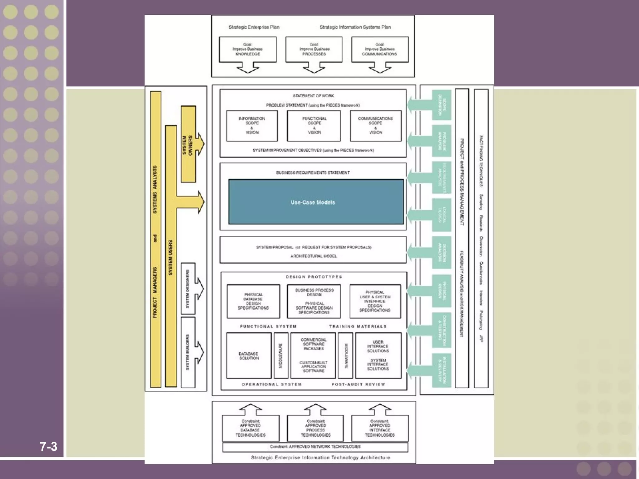
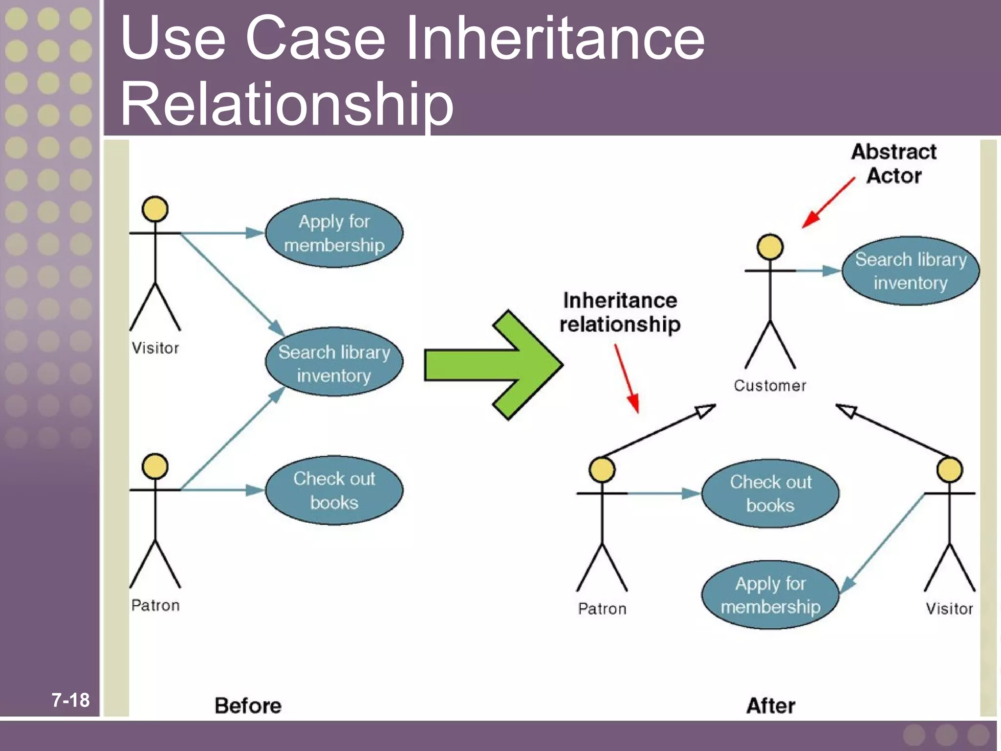
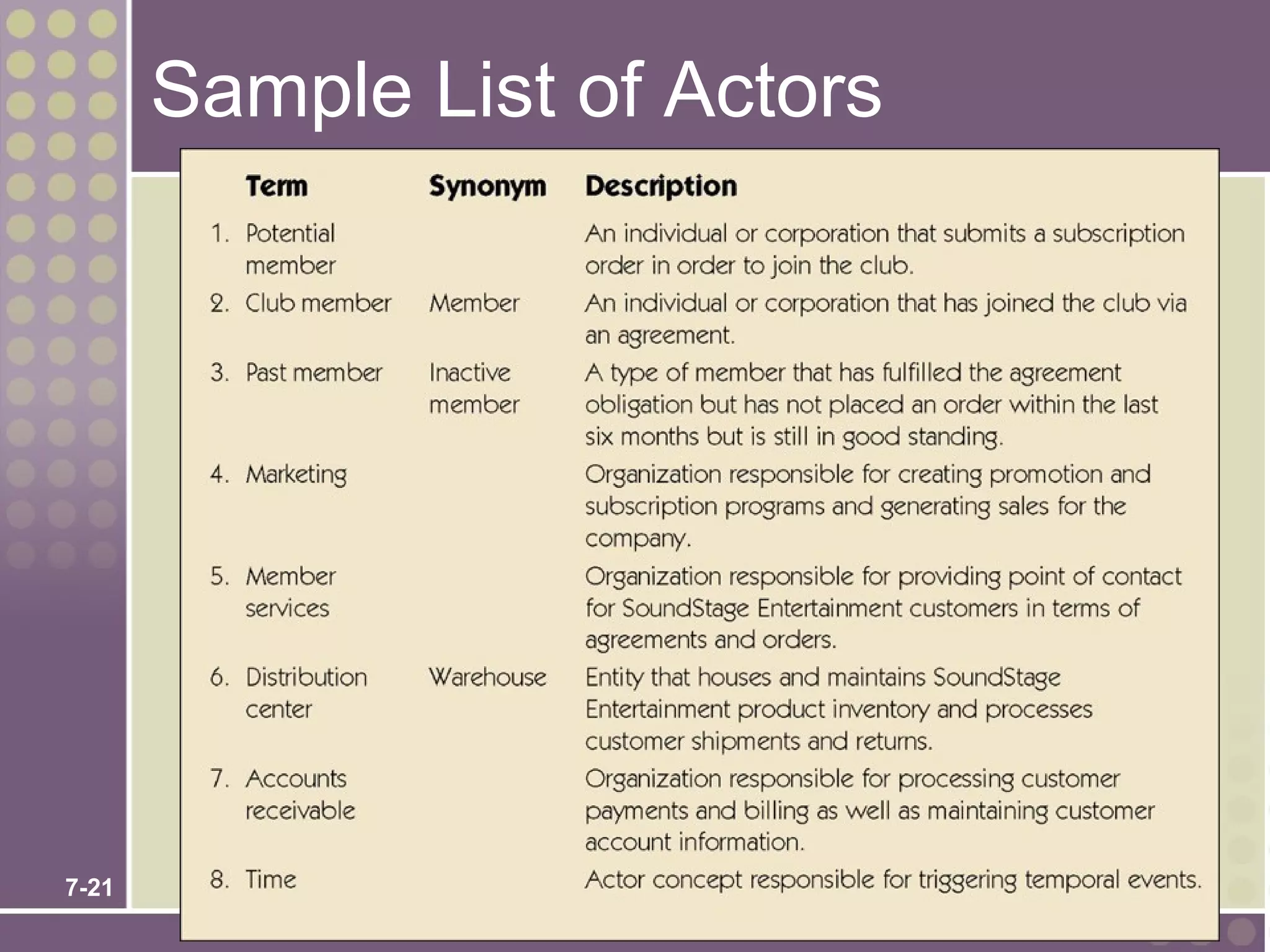
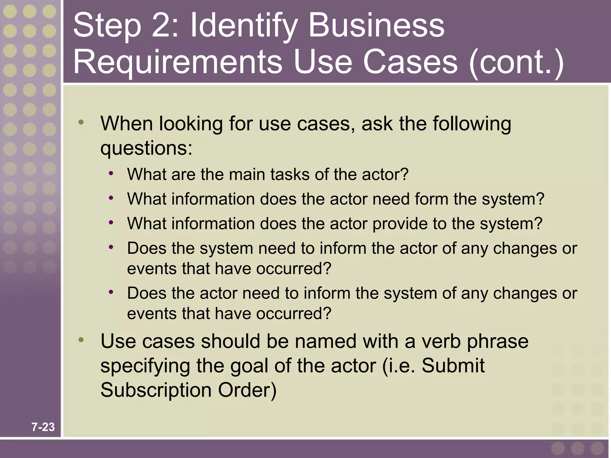
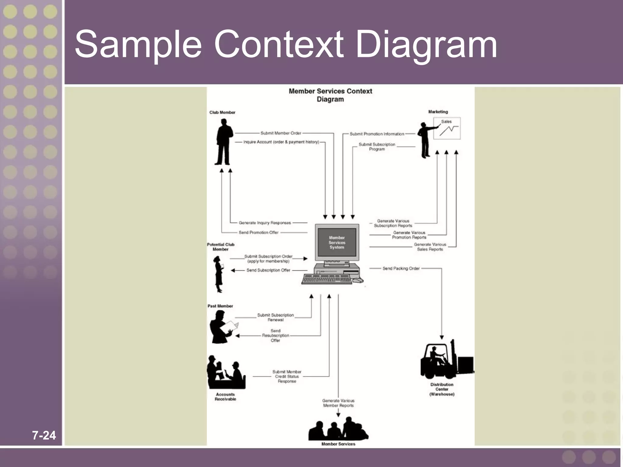
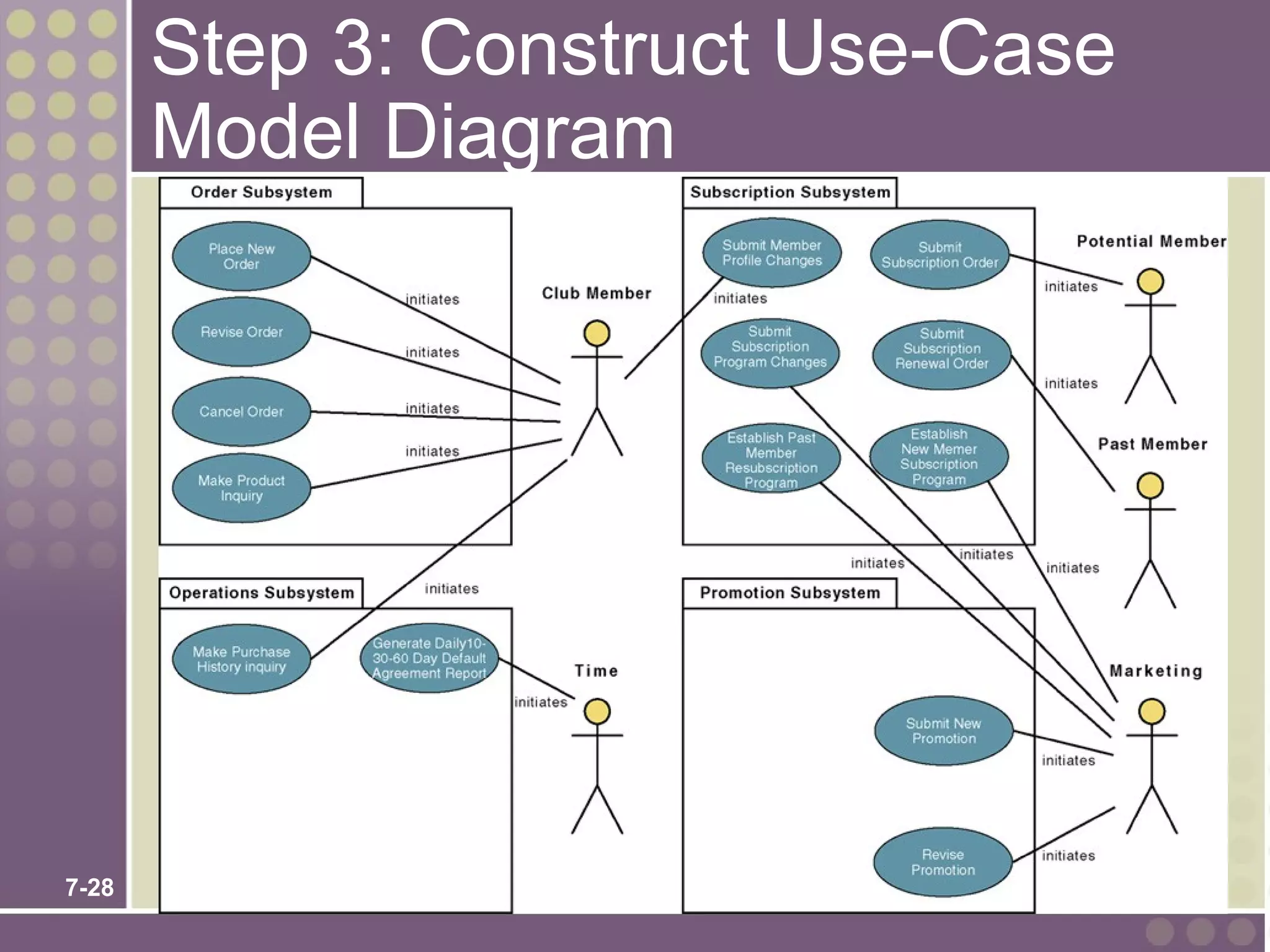
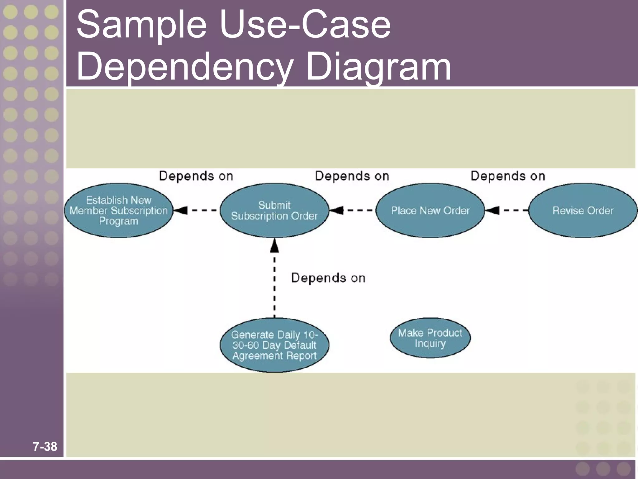
This chapter discusses use case modeling for system requirements. It defines key concepts like actors, use cases, use case diagrams and narratives. It describes the benefits of use case modeling for capturing functional requirements, communicating with stakeholders, and aiding project estimation and management. The chapter outlines the process for developing a use case model, including identifying actors and use cases, constructing diagrams, and documenting narratives. It provides examples of use case relationships like association, extension, inheritance and dependencies.
The document discusses use case diagrams and use case descriptions for modeling system requirements. It covers drawing use case diagrams to show functional requirements and actors, common mistakes, and writing use case descriptions including basic, alternate, and exception flows of events. The document provides examples and exercises to help understand use cases for requirements modeling.
Use case diagrams describe interactions between actors and a system to accomplish goals. A use case diagram typically includes:
1) Actors that interact with the system from outside, such as users or other systems. Common actor types are primary actors whose goals are fulfilled by the system and supporting actors that provide services.
2) Use cases that represent functions or tasks performed by the system. They are connected to relevant actors and may have relationships like include and extend.
3) Relationships between use cases like include, which shows a use case incorporating another, and extend, where a use case optionally extends another.
Use case diagrams provide an overview of a system's functions and how outside actors interact with them at a
This document provides an overview of topics covered in Chapter 7 on software design and implementation, including object-oriented design using UML, design patterns, implementation issues, and open source development. It discusses the design and implementation process, build vs buy approaches, object-oriented design processes involving system models, and key activities like defining system context, identifying objects and interfaces. Specific examples are provided for designing a wilderness weather station system.
UML (Unified Modeling Language) is a standard modeling language used to specify, visualize, construct and document software systems. It uses graphical notations to express the design of object-oriented software projects. UML includes diagrams, relationships and elements that help design different perspectives of a system including design, implementation, process and deployment. The key building blocks of UML are things (like classes and use cases), relationships (like generalization and dependency), and diagrams (like class, sequence and deployment diagrams) which are used to model different aspects of a software system.
The document provides an introduction to UML diagrams, including use case diagrams, class diagrams, and state diagrams. It describes the purpose and notation of each type of diagram. Use case diagrams model user interactions and goals. Class diagrams describe the static structure of a system through classes, attributes, and relationships. State diagrams specify the different states an object can be in and the transitions between states. Examples of each diagram type are provided for common systems like a library management system.
The document discusses architectural design in software engineering. It covers topics like architectural design decisions, views, patterns, and application architectures. Architectural design involves identifying major system components and their communications in order to represent the link between specification and design processes. Common architectural patterns discussed include model-view-controller, layered architectures, repositories, client-server, pipes and filters. The document also provides examples of architectures for different types of applications like transaction processing systems and information systems.
Component-based software engineering (CBSE) is a process that emphasizes designing and building systems using reusable software components. It emerged from failures of object-oriented development to enable effective reuse. CBSE follows a "buy, don't build" philosophy where requirements are met through available components rather than custom development. The CBSE process involves identifying components, qualifying them, adapting them if needed, and assembling them within an architectural design. This leverages reuse for increased quality, productivity, and reduced development time compared to traditional software engineering approaches.
UML (Unified Modeling Language) is a standardized modeling language used to visualize, specify, construct and document artifacts of a software system. It can be used to model both software and non-software systems. The document discusses the history, features, diagrams and real-world applications of UML. It also covers advantages like being easy to understand and standardized, as well as disadvantages such as difficulty synchronizing models with code. Finally, it briefly describes several open source UML modeling tools.
This document discusses agile software development methods. It covers topics like agile principles, extreme programming practices including test-driven development and pair programming. It also discusses scaling agile methods to larger projects using scrum, with sprints and daily stand-up meetings. Some challenges of applying agile to large, long-term projects with distributed teams are also outlined.
State chart diagrams define the different states an object can be in during its lifetime, and how it transitions between states in response to events. They are useful for modeling reactive systems by describing the flow of control from one state to another. The key elements are initial and final states, states represented by rectangles, and transitions between states indicated by arrows. State chart diagrams are used to model the dynamic behavior and lifetime of objects in a system and identify the events that trigger state changes.
Software requirements specification of Library Management SystemSoumili Sen
The document provides requirements for a Library Management System. It includes 3 or less sentences:
The Library Management System aims to computerize library processes like book borrowing and maintain member and book details in a database. It will allow librarians and members to search for books, view member accounts, and generate reports. The system needs to be secure, fast, and compatible with common browsers and operating systems.
UML (Unified Modeling Language) is a standard language for specifying, visualizing, and documenting software systems. It uses various diagrams to model different views of a system, such as structural diagrams (e.g. class diagrams), behavioral diagrams (e.g. sequence diagrams), and deployment diagrams. The key building blocks of UML include things (classes, interfaces, use cases), relationships (associations, generalizations), and diagrams. UML aims to provide a clear blueprint of software systems for both technical and non-technical audiences.
This document provides an overview of use case diagrams and use cases. It defines what a use case is, including that it captures a user's interaction with a system to achieve a goal. It describes the key components of a use case diagram, including actors, use cases, and relationships between use cases like generalization, inclusion, and extension. An example use case diagram for a money withdrawal from an ATM is presented to illustrate these concepts. Guidelines for documenting use cases with descriptions of flows, exceptions, and other details are also provided.
The 4+1 view model was designed by Philippe Kruchten as a framework for describing the architecture of software systems using multiple views. It defines four primary views - logical, development, process, and physical - as well as a supplementary scenarios or use cases view. Each view represents a different stakeholder perspective and allows separation of architectural concerns through the use of modeling diagrams like UML.
The document discusses the Unified Modeling Language (UML). UML is a general-purpose modeling language used to specify, visualize, construct, and document software systems. It captures decisions and understanding about systems that must be constructed. The goals of UML included developing a modeling language that could be used across different domains and development methods. UML has three main building blocks - things, relationships, and diagrams. Things represent elements in a model like classes, components, and use cases. Relationships connect things and show dependencies, generalizations, and associations. Diagrams provide different views of UML models, including structural diagrams and behavioral diagrams.
Introduction to Unified Modeling LanguageAMITJain879
The document provides an introduction to the Unified Modeling Language (UML). It discusses that UML is a modeling language used to visualize, specify, construct and document software artifacts. UML provides notations like rectangles, lines and ellipses to create visual models of systems. It also standardizes existing object-oriented modeling notations. The conceptual model of UML has three main elements - things, relationships, and diagrams. Things can be structural, behavioral, grouping or annotational. Relationships show how elements are associated. Diagrams provide different perspectives of software systems.
This document provides an overview of use case diagrams in object oriented design and analysis. It defines key components of a use case diagram including actors, use cases, the system boundary, and relationships between these elements. Actors represent people or systems that interact with the system, while use cases describe specific functions or services provided by the system. Relationships such as include, extend, and association are used to connect actors to use cases and illustrate how use cases relate to each other. The purpose of a use case diagram is to depict the functionality of a system from the user's perspective and illustrate the developer's understanding of user requirements.
This document provides an overview of use case diagrams and their components. It discusses actors, use cases, associations, generalizations, includes and extends relationships. It provides examples of use case diagrams and explains when to use certain relationships. The key points are that use case diagrams model a system's functionality from the user's perspective, show actors and their goals, and use relationships to structure common or optional behaviors between use cases.
The document discusses sequence diagrams, which show the interaction between objects and classes through a sequence of messages. Sequence diagrams are useful during the design phase to help understand system design and object interactions. They can also be used to document how existing systems work by showing the sequence of messages exchanged between objects.
UML (Unified Modeling Language) is a standard language for specifying, visualizing, constructing and documenting software systems. It uses mainly graphical notations to express design of software projects. There are two main categories of UML diagrams - structural diagrams which focus on static elements regardless of time, and behavioral diagrams which focus on dynamic features and business processes. Common UML diagram types include class, sequence, use case, activity, state machine, component, deployment and interaction diagrams.
System modeling involves creating abstract models of a system from different perspectives, such as context, interactions, structure, and behavior. These models help analysts understand system functionality and communicate with customers. Context models show a system's external environment and relationships. Interaction models, such as use case and sequence diagrams, depict how users and systems interact. Structural models, like class diagrams, represent a system's internal organization. Behavioral models, including activity and state diagrams, illustrate a system's dynamic response to events or data. Model-driven engineering aims to generate implementation from system models.
This document provides an introduction to software engineering topics including:
1. What software engineering is, its importance, and the software development lifecycle activities it encompasses.
2. The many different types of software systems that exist and how software engineering approaches vary depending on the application.
3. Key fundamentals of software engineering that apply universally, including managing development processes, dependability, and reusing existing software components.
The Unified Process (UP) is a software development process that provides guidance on team activities and work integration. It originated from issues with traditional processes being too diverse and outdated. Key aspects of UP include being use-case driven, architecture-centric, and iterative/incremental. UP follows a lifecycle of inception, elaboration, construction, and transition phases within iterative development cycles. While UP addressed issues with prior methods, its weaknesses include not covering the full software process and tools-focus not suiting complex systems.
This document provides an introduction to the Unified Modeling Language (UML). It defines UML as a standard modeling language used to visualize, specify, construct and document software systems. The document outlines the basics of UML including common diagram types like use case diagrams, class diagrams and sequence diagrams. It also discusses modeling tools that support working with UML diagrams.
This slide give the basic introduction about UML diagram and it's types, and brief intro about Activity Diagram, use of activity diagram in object oriented programming language..
This document provides an overview of UML class diagrams, including their purpose and essential elements. A UML class diagram visually describes the structure of a system by showing classes, attributes, operations, and relationships. Key elements include classes, associations, generalization, dependencies, and notes. The document also provides examples and tips for creating UML class diagrams.
The Unified Modeling Language (UML) is a general-
purpose, developmental, modeling language in the field
of software engineering, that is intended to provide a
standard way to visualize the design of a system.
The chapter discusses use case modeling for system requirements. It defines key concepts like actors, use cases, use case diagrams and narratives. The benefits of use case modeling include capturing functional requirements, communicating with users, and establishing test cases. Use case modeling provides a user-centered approach to defining a system's scope and functionality.
This document contains use case narratives for editing, designing, and managing events on Eventbrite. It describes the main success scenarios and alternative sequences for editing event details, choosing a design layout, and modifying fields like invite options, order settings, and attendee management. The narratives provide an overview of the key steps and functions for creating and customizing events on the Eventbrite platform.
The document discusses requirements capture using UML use case diagrams. It describes how use case diagrams can be used to capture functional requirements by modeling actors, use cases, and relationships. Key aspects covered include identifying use cases and actors, documenting use case descriptions, modeling relationships between use cases and actors, and tips for effective use case modeling.
Creately offers many Use Case diagram templates which you can use instantly to create your own Use Case diagrams. Many UML Use Case diagram templates can be found on our diagram community. Just click on the use as templates button to immediately start modifying it using our online diagramming tools.
The document discusses use case diagrams in object oriented design and analysis. It defines use cases as descriptions of system functionality from a user perspective. Use case diagrams depict system behavior, users, and relationships between actors, use cases, and other use cases. The key components of use case diagrams are described as actors, use cases, the system boundary, and relationships. Common relationships include association, extend, generalization, uses, and include. An example use case diagram for a cellular telephone is provided to illustrate these concepts.
A consulting firm needs to redesign their client technology tracking system and service request system. The current systems for tracking client hardware/software configurations, submitting service requests, and recording work done are inefficient. The proposed solution is a new integrated system that allows clients to submit service requests online, technicians to view requests and document work, and all users to view the status and history of requests. The system would also track client hardware and software configurations.
This document contains examples of various UML diagrams including use case diagrams, class diagrams, state diagrams, sequence diagrams, collaboration diagrams, component diagrams, and deployment diagrams. It also includes descriptions of concepts like forward engineering, reverse engineering, and modeling software systems.
A Context Diagram for Business Transformation & Related DomainsRobert Bratulic
How do terms like Business Transformation, Business Architecture, Business Process, and Business Analysis relate?
This is a Venn diagram that is an informal, intuitive and incomplete depiction of how these domains overlap, don’t overlap, and depend on each other.
Goal: to stimulate further exchange and discussion.
How to detect side channel attacks in cloud infrastructuresPasquale Puzio
http://www.secludit.com
We integrated Elastic Detector, which is SecludIT's product, with OSSIM in order to detect side-channel attacks occurring in cloud infrastructures.
Elastic Detector takes care of solving the cloud elasticity issue, collecting security-relevant logs and forwarding (rsyslog) them to OSSIM where the correlation takes place (thanks to our plugin).
DEMO showed at the RaSIEM workshop (ARES conference) in Regensburg, Germany.
This document outlines a proposed smart railway ticketing system that features web-based and mobile ticketing, credit/mobile payments, barcode tickets, and integration with existing systems. Key aspects include interconnecting stations and payment providers, implementing a web portal, designing tickets and readers, and establishing data centers for up to 3 years. Risks include changing requirements, user adoption challenges, and technical/integration issues.
This document describes three use cases for a Codecademy online learning platform: 1) Create Project, which outlines the steps for a user to create a new programming project, 2) Learn, which outlines how a user can learn a new programming language through projects, and 3) Edit Settings, which describes how a user can edit their profile settings like username and email. Each use case includes actors, preconditions, success scenarios, alternative scenarios, and post-conditions.
The document describes the Enhanced Telecom Operations Map (eTOM) Business Process Framework Release 6.0. It provides information on where to find the complete eTOM documentation online. It also includes a poster with the eTOM framework, which outlines various business processes related to enterprise management, strategy, infrastructure, product operations, operations support, fulfillment, billing, service management, resource management, supplier/partner relationship management, and customer relationship management.
The music video for "Playing with Fire" by Plan B tells the story of a young man named Jake who gets trapped in a London gang. It shows how gangs lure and coerce vulnerable youth. The video has a linear narrative structure, following Jake's progression into the gang. It illustrates the lyrics of the song and aims to spark social change by showing the harsh realities of gang life.
FastAsset is an asset recovery company established in 1997 that provides logistics, repair, parts sourcing, and data destruction services for returned consumer electronics. It has facilities across the US and serves clients in industries like computers, printers, phones, gaming consoles, and more. FastAsset grades returned products, sources parts for repair, repackages units, provides warranty support, and remarkets items to enhance returns for its clients while using green recycling practices.
The document discusses a feedback device called the I am... system that is designed to help coaches protect runners from injury by monitoring their fatigue and pain levels. It costs $50-100 per hour for a running coach, but the I am... system is an affordable alternative starting at $14.99 for a 3 month subscription. The startup was accepted into an incubator program and has recruited experts in various fields like neuroscience, biomechanics, and engineering to help develop the product and business model.
The Social Studies Group was hired by a consumer electronics company to gain insights into consumer opinions of new product models and their user experience (UX) features through social media analysis. SSG used Brandwatch to:
1. Isolate discussions about specific product models and UX features from a large volume of online consumer electronics discussions.
2. Analyze sentiment towards different models' UX features and qualities through flexible searches that categorized discussions by location, stage of buying cycle, and emotions.
3. Present results like model comparisons and visualizations of sentiment towards individual features to inform the client's next product designs.
The document discusses use case diagrams and modeling. Use case diagrams capture system requirements and define interactions between actors and the system. Components include actors, represented by stick figures, and use cases, represented by ellipses. Use cases describe a unit of work and can include name, description, requirements, constraints, and scenarios. Relationships between use cases include include, extend, and inherit. Include references a lower-level use case. Extend adds additional sequences. Inherit replaces scenarios. Boundaries show actors outside and use cases inside the system. Steps should show actor goals, not interfaces.
Case study how to apply for the co-funding from MoST China for Horizon 2020 p...Dragonstarproject
This document summarizes the process for Chinese organizations to apply for co-funding from China's Ministry of Science and Technology (MOST) for projects that have received funding from the European Union's Horizon 2020 program. It outlines that Chinese partners in Horizon 2020 proposals can jointly apply for matching funds from MOST. The application involves filling out basic information and proposal forms online through MOST's project application system by the deadline. The co-funding is aimed at further facilitating research collaboration between European and Chinese organizations.
This document discusses requirements engineering for software projects. It begins by defining what requirements are, noting that they can range from abstract statements to detailed specifications. There are three types of requirements documents: requirements definition for customers, requirements specification for contracts, and software specifications for developers. The document outlines the sources of requirements, key tasks in requirements engineering like elicitation and validation, and challenges in getting requirements right. It also discusses techniques for gathering requirements like inception, collaborative meetings, use cases, and elaboration of requirements into an analysis model.
The document discusses use case diagrams and their components. It defines key terms like actors, use cases, and relationships between use cases. It explains that use case diagrams model interactions between actors and a system, and capture the system's functional requirements. Diagrams show actors outside the system boundary and use cases inside it. Relationships like "include", "extend", and "generalization" define relationships between use cases. The document provides examples and guidelines for creating use case specifications that describe use case scenarios in detail.
Use case diagrams depict the functionality of a system from a user perspective by showing actors, use cases, and relationships between them. Actors represent roles that interact with the system, while use cases represent system functions. Relationships include association, extend, generalization, uses, and include. Each use case contains details like preconditions, postconditions, normal and alternative flows, and exceptions. Use cases are identified through actor-based and event-based methods by determining actor tasks and system responses to external events.
Requirement analysis and UML modelling in Software engineeringsnehalkulkarni74
Receptionist
Patient: Patient
Doctor: Doctor
- The vertical solid line represents the life of an
object.
- It runs from top to bottom.
Messages:-
- The arrow represents the message passing
between objects.
- The arrow head points to the receiver.
- The message name is written near arrow.
- Synchronous and asynchronous message
Receptionist
Patient
Doctor
makeAppointment()
checkAvailability()
scheduleAppointment()
confirmAppointment()
treatPatient()
billPatient()
- Sequence diagram shows the time sequence of
messages between objects.
- It emphasizes on
Lab 3 Introduction to the UML - how to create a use case diagramFarah Ahmed
The document discusses use case diagrams and use case modeling. It provides an overview of use case diagrams, including their purpose and components. Key points include:
- Use case diagrams show interactions between actors and the system/software being modeled through use cases. They are used early in development to capture requirements and later to specify system behavior.
- Components of a use case diagram include actors, use cases, and relationships between them like generalization, include, and extend. Actors represent roles that interact with the system while use cases represent system functions/processes.
- Examples of a use case diagram for a vehicle sales system are provided to demonstrate how actors, use cases, and relationships can be modeled visually. Guidance is
The document discusses software engineering concepts related to eliciting requirements and developing use cases. It defines eliciting requirements as collecting requirements through collaborative meetings between developers and customers. Key steps in eliciting requirements include quality function deployment to translate customer needs to technical requirements. Usage scenarios help understand how end users will utilize features. Developing use cases describes them as sequences of user-system interactions to achieve a goal from the user's perspective. Actors represent roles that interact with the system, and user stories provide abbreviated use case descriptions in a problem/solution format.
UML was developed to standardize object-oriented modeling notations. It consolidated techniques like OMT, OOSE, and the Booch Methodology. UML provides multiple views (diagrams) to model a system, including structural, behavioral, implementation, and environmental views. Common UML diagrams are use case diagrams, which model functionality from the user's perspective, and class diagrams, which show system structure.
This document provides an overview of requirement elicitation, analysis, and specification for object-oriented software engineering. It discusses techniques for requirement elicitation including questionnaires, task analysis, interviews, scenarios, and use cases. It also describes requirement elicitation activities such as identifying actors, scenarios, use cases, and refining requirements. Additionally, it covers functional and non-functional requirements, correctness, completeness, consistency and other concepts related to requirement specification. Finally, it includes a requirements analysis document template.
Storyboarding is a visual technique used in software requirements engineering to help understand user needs and system functionality. It involves creating a series of illustrations that show how a user will interact with a proposed system. Storyboards have benefits like communicating design ideas clearly and allowing feedback before development. Prototyping creates a mock-up of a proposed system to help validate requirements with users. Use cases are written descriptions of how users will perform tasks with a system. They define the actors, scenarios, and goals to help specify requirements.
Lecture no 8 use case modeling and use case diagramsnaveed428
The document discusses use case modeling and diagrams. It provides examples of use cases, actors, and relationships between them. Some key points:
- A use case represents a goal of an actor and the interactions needed to achieve that goal. Actors can be people or other systems.
- Use case diagrams show use cases, actors, and their relationships to understand system requirements and functionality.
- Common relationships include generalization, extension, and inclusion to model optional/exceptional behavior or reuse of common interactions.
- Well-defined use cases with descriptions help validate requirements, guide testing, and communicate with stakeholders.
The document discusses elements of an analysis model for software engineering requirements, including use case diagrams. It provides information on use cases, actors, relationships between use cases and actors, and how to describe use cases using user stories, diagrams, and textual descriptions. An example use case diagram is also included to illustrate these concepts.
The document discusses use case modeling and UML diagrams. It provides an overview of commonly used UML diagrams such as use case diagrams, activity diagrams, class diagrams, sequence diagrams, and collaboration diagrams. It then describes use cases, use case diagrams, and relationships between use cases including include, extend, and generalize relationships.
The document provides an overview of Software Requirement Specification (SRS) and Software Quality Assurance (SQA). It discusses the importance of well-written requirements documents, as without them developers do not know what to build and customers do not know what to expect. The document also outlines different types of requirements like functional, non-functional, user and system requirements. It describes various requirements elicitation techniques like interviews, brainstorming sessions, use case approach etc. Finally, it discusses modeling requirements using tools like data flow diagrams, data dictionaries and entity relationship diagrams.
The document discusses object-oriented system development and modeling. It covers topics like:
1. The main stages of traditional system development life cycles like requirements, analysis, design, implementation, and installation. As well as common life cycle models like waterfall, V-model, spiral, and prototyping.
2. Phases of object-oriented development focus on the state of the system rather than activities, including inception, elaboration, construction, and transition.
3. Modeling techniques for object-oriented systems including the Unified Modeling Language (UML), Rational Unified Process (RUP), abstraction, decomposition, and class-responsibility-collaboration (CRC) cards.
4
The document discusses the key processes in requirements engineering, including feasibility studies, elicitation, analysis, validation and management. It describes common activities like elicitation techniques using interviews, scenarios and use cases. It emphasizes that requirements evolve over time in response to changing stakeholder needs and environments, and that validation and management processes are needed to handle this evolution.
Requirements engineering emphasizes using systematic techniques to ensure requirements are complete, consistent, and relevant. It encompasses seven tasks: inception, elicitation, elaboration, negotiation, specification, validation, and management. Requirements are statements of what the system must do, how it must behave, and its properties. Requirements engineering produces work products like use cases, class diagrams, and state diagrams to model system behavior and structure. Stakeholder negotiation and validation are important to agree on realistic requirements.
Use case modeling is a technique for capturing requirements by describing how system actors interact with the system. Key aspects of use case modeling include: identifying actors and use cases; creating a use case diagram; describing use cases and their flows; and identifying relationships between use cases using include, extend, and generalization. Use case modeling helps elicit requirements, communicate with stakeholders, and generate test cases. The analysis process involves developing problem statements, identifying actors and use cases, creating an initial diagram, describing use cases, and refining the model through elaboration and prioritization.
Presentation Use Case Diagram and Use Case Specification.pptxazida3
The use case diagram models the interactions between a Customer and an ATM machine. The Customer can perform the use cases of Logging In, Making a Withdrawal, Checking Balance, and Depositing Funds. The ATM machine facilitates these use cases.
The document discusses the key activities in requirements engineering including inception, elicitation, analysis modeling, negotiation and validation. It describes techniques used in each stage such as use cases, class and state diagrams to model requirements. Quality function deployment and patterns are also discussed as tools to help define and organize requirements.
Building Production Ready Search Pipelines with Spark and MilvusZilliz
Spark is the widely used ETL tool for processing, indexing and ingesting data to serving stack for search. Milvus is the production-ready open-source vector database. In this talk we will show how to use Spark to process unstructured data to extract vector representations, and push the vectors to Milvus vector database for search serving.
Driving Business Innovation: Latest Generative AI Advancements & Success StorySafe Software
Are you ready to revolutionize how you handle data? Join us for a webinar where we’ll bring you up to speed with the latest advancements in Generative AI technology and discover how leveraging FME with tools from giants like Google Gemini, Amazon, and Microsoft OpenAI can supercharge your workflow efficiency.
During the hour, we’ll take you through:
Guest Speaker Segment with Hannah Barrington: Dive into the world of dynamic real estate marketing with Hannah, the Marketing Manager at Workspace Group. Hear firsthand how their team generates engaging descriptions for thousands of office units by integrating diverse data sources—from PDF floorplans to web pages—using FME transformers, like OpenAIVisionConnector and AnthropicVisionConnector. This use case will show you how GenAI can streamline content creation for marketing across the board.
Ollama Use Case: Learn how Scenario Specialist Dmitri Bagh has utilized Ollama within FME to input data, create custom models, and enhance security protocols. This segment will include demos to illustrate the full capabilities of FME in AI-driven processes.
Custom AI Models: Discover how to leverage FME to build personalized AI models using your data. Whether it’s populating a model with local data for added security or integrating public AI tools, find out how FME facilitates a versatile and secure approach to AI.
We’ll wrap up with a live Q&A session where you can engage with our experts on your specific use cases, and learn more about optimizing your data workflows with AI.
This webinar is ideal for professionals seeking to harness the power of AI within their data management systems while ensuring high levels of customization and security. Whether you're a novice or an expert, gain actionable insights and strategies to elevate your data processes. Join us to see how FME and AI can revolutionize how you work with data!
In the rapidly evolving landscape of technologies, XML continues to play a vital role in structuring, storing, and transporting data across diverse systems. The recent advancements in artificial intelligence (AI) present new methodologies for enhancing XML development workflows, introducing efficiency, automation, and intelligent capabilities. This presentation will outline the scope and perspective of utilizing AI in XML development. The potential benefits and the possible pitfalls will be highlighted, providing a balanced view of the subject.
We will explore the capabilities of AI in understanding XML markup languages and autonomously creating structured XML content. Additionally, we will examine the capacity of AI to enrich plain text with appropriate XML markup. Practical examples and methodological guidelines will be provided to elucidate how AI can be effectively prompted to interpret and generate accurate XML markup.
Further emphasis will be placed on the role of AI in developing XSLT, or schemas such as XSD and Schematron. We will address the techniques and strategies adopted to create prompts for generating code, explaining code, or refactoring the code, and the results achieved.
The discussion will extend to how AI can be used to transform XML content. In particular, the focus will be on the use of AI XPath extension functions in XSLT, Schematron, Schematron Quick Fixes, or for XML content refactoring.
The presentation aims to deliver a comprehensive overview of AI usage in XML development, providing attendees with the necessary knowledge to make informed decisions. Whether you’re at the early stages of adopting AI or considering integrating it in advanced XML development, this presentation will cover all levels of expertise.
By highlighting the potential advantages and challenges of integrating AI with XML development tools and languages, the presentation seeks to inspire thoughtful conversation around the future of XML development. We’ll not only delve into the technical aspects of AI-powered XML development but also discuss practical implications and possible future directions.
GraphSummit Singapore | The Art of the Possible with Graph - Q2 2024Neo4j
Neha Bajwa, Vice President of Product Marketing, Neo4j
Join us as we explore breakthrough innovations enabled by interconnected data and AI. Discover firsthand how organizations use relationships in data to uncover contextual insights and solve our most pressing challenges – from optimizing supply chains, detecting fraud, and improving customer experiences to accelerating drug discoveries.
Programming Foundation Models with DSPy - Meetup SlidesZilliz
Prompting language models is hard, while programming language models is easy. In this talk, I will discuss the state-of-the-art framework DSPy for programming foundation models with its powerful optimizers and runtime constraint system.
Communications Mining Series - Zero to Hero - Session 1DianaGray10
This session provides introduction to UiPath Communication Mining, importance and platform overview. You will acquire a good understand of the phases in Communication Mining as we go over the platform with you. Topics covered:
• Communication Mining Overview
• Why is it important?
• How can it help today’s business and the benefits
• Phases in Communication Mining
• Demo on Platform overview
• Q/A
Removing Uninteresting Bytes in Software FuzzingAftab Hussain
Imagine a world where software fuzzing, the process of mutating bytes in test seeds to uncover hidden and erroneous program behaviors, becomes faster and more effective. A lot depends on the initial seeds, which can significantly dictate the trajectory of a fuzzing campaign, particularly in terms of how long it takes to uncover interesting behaviour in your code. We introduce DIAR, a technique designed to speedup fuzzing campaigns by pinpointing and eliminating those uninteresting bytes in the seeds. Picture this: instead of wasting valuable resources on meaningless mutations in large, bloated seeds, DIAR removes the unnecessary bytes, streamlining the entire process.
In this work, we equipped AFL, a popular fuzzer, with DIAR and examined two critical Linux libraries -- Libxml's xmllint, a tool for parsing xml documents, and Binutil's readelf, an essential debugging and security analysis command-line tool used to display detailed information about ELF (Executable and Linkable Format). Our preliminary results show that AFL+DIAR does not only discover new paths more quickly but also achieves higher coverage overall. This work thus showcases how starting with lean and optimized seeds can lead to faster, more comprehensive fuzzing campaigns -- and DIAR helps you find such seeds.
- These are slides of the talk given at IEEE International Conference on Software Testing Verification and Validation Workshop, ICSTW 2022.
Dr. Sean Tan, Head of Data Science, Changi Airport Group
Discover how Changi Airport Group (CAG) leverages graph technologies and generative AI to revolutionize their search capabilities. This session delves into the unique search needs of CAG’s diverse passengers and customers, showcasing how graph data structures enhance the accuracy and relevance of AI-generated search results, mitigating the risk of “hallucinations” and improving the overall customer journey.
Why You Should Replace Windows 11 with Nitrux Linux 3.5.0 for enhanced perfor...SOFTTECHHUB
The choice of an operating system plays a pivotal role in shaping our computing experience. For decades, Microsoft's Windows has dominated the market, offering a familiar and widely adopted platform for personal and professional use. However, as technological advancements continue to push the boundaries of innovation, alternative operating systems have emerged, challenging the status quo and offering users a fresh perspective on computing.
One such alternative that has garnered significant attention and acclaim is Nitrux Linux 3.5.0, a sleek, powerful, and user-friendly Linux distribution that promises to redefine the way we interact with our devices. With its focus on performance, security, and customization, Nitrux Linux presents a compelling case for those seeking to break free from the constraints of proprietary software and embrace the freedom and flexibility of open-source computing.
GraphSummit Singapore | The Future of Agility: Supercharging Digital Transfor...Neo4j
Leonard Jayamohan, Partner & Generative AI Lead, Deloitte
This keynote will reveal how Deloitte leverages Neo4j’s graph power for groundbreaking digital twin solutions, achieving a staggering 100x performance boost. Discover the essential role knowledge graphs play in successful generative AI implementations. Plus, get an exclusive look at an innovative Neo4j + Generative AI solution Deloitte is developing in-house.
Cosa hanno in comune un mattoncino Lego e la backdoor XZ?Speck&Tech
ABSTRACT: A prima vista, un mattoncino Lego e la backdoor XZ potrebbero avere in comune il fatto di essere entrambi blocchi di costruzione, o dipendenze di progetti creativi e software. La realtà è che un mattoncino Lego e il caso della backdoor XZ hanno molto di più di tutto ciò in comune.
Partecipate alla presentazione per immergervi in una storia di interoperabilità, standard e formati aperti, per poi discutere del ruolo importante che i contributori hanno in una comunità open source sostenibile.
BIO: Sostenitrice del software libero e dei formati standard e aperti. È stata un membro attivo dei progetti Fedora e openSUSE e ha co-fondato l'Associazione LibreItalia dove è stata coinvolta in diversi eventi, migrazioni e formazione relativi a LibreOffice. In precedenza ha lavorato a migrazioni e corsi di formazione su LibreOffice per diverse amministrazioni pubbliche e privati. Da gennaio 2020 lavora in SUSE come Software Release Engineer per Uyuni e SUSE Manager e quando non segue la sua passione per i computer e per Geeko coltiva la sua curiosità per l'astronomia (da cui deriva il suo nickname deneb_alpha).
HCL Notes and Domino License Cost Reduction in the World of DLAUpanagenda
Webinar Recording: https://www.panagenda.com/webinars/hcl-notes-and-domino-license-cost-reduction-in-the-world-of-dlau/
The introduction of DLAU and the CCB & CCX licensing model caused quite a stir in the HCL community. As a Notes and Domino customer, you may have faced challenges with unexpected user counts and license costs. You probably have questions on how this new licensing approach works and how to benefit from it. Most importantly, you likely have budget constraints and want to save money where possible. Don’t worry, we can help with all of this!
We’ll show you how to fix common misconfigurations that cause higher-than-expected user counts, and how to identify accounts which you can deactivate to save money. There are also frequent patterns that can cause unnecessary cost, like using a person document instead of a mail-in for shared mailboxes. We’ll provide examples and solutions for those as well. And naturally we’ll explain the new licensing model.
Join HCL Ambassador Marc Thomas in this webinar with a special guest appearance from Franz Walder. It will give you the tools and know-how to stay on top of what is going on with Domino licensing. You will be able lower your cost through an optimized configuration and keep it low going forward.
These topics will be covered
- Reducing license cost by finding and fixing misconfigurations and superfluous accounts
- How do CCB and CCX licenses really work?
- Understanding the DLAU tool and how to best utilize it
- Tips for common problem areas, like team mailboxes, functional/test users, etc
- Practical examples and best practices to implement right away
UiPath Test Automation using UiPath Test Suite series, part 5DianaGray10
Welcome to UiPath Test Automation using UiPath Test Suite series part 5. In this session, we will cover CI/CD with devops.
Topics covered:
CI/CD with in UiPath
End-to-end overview of CI/CD pipeline with Azure devops
Speaker:
Lyndsey Byblow, Test Suite Sales Engineer @ UiPath, Inc.
2. Objectives
• Describe the benefits of use-case modeling.
• Define actors and use cases and be able to identify
them from context diagrams and other sources.
• Describe the relationships that can appear on a use-
case model diagram.
• Describe the steps for preparing a use-case model.
• Describe how to construct a use-case model diagram.
• Describe the various sections of a use-case narrative
and be able to prepare one.
• Define the purpose of the use-case ranking and priority
matrix and the use-case dependency diagram.
7-2
4. An Introduction to
Use-Case Modeling
• One of the primary challenges is the ability to
elicit the correct and necessary system
requirements from the stakeholders and
specify them in a manner understandable to
them so those requirements can be verified
and validated.
The hardest single part of building a software system is deciding precisely
what to build. No other part of the conceptual work is a difficult as
establishing the detailed technical requirements, including all the interfaces
to people, to machines, and to other software systems. No other work so
cripples the resulting system if done wrong. No other part is more difficult
to rectify later. Fred Brooks
7-4
5. IS Development Project
Track Record
canceled Over budget,
before late, or without
completion needed features
7-5 Source: The Standish Group International, Inc., “Chaos: A Recipe for Success”
6. User-Centered Development
and Use-Case Modeling
User-centered development – a process of
systems development based on understanding
the needs of the stakeholders and the reasons
why the system should be developed.
Use-case modeling – the process of modeling
a system’s functions in terms of business
events, who initiated the events, and how the
system responds to those events.
• Use-case modeling has roots in object-oriented modeling.
• Gaining popularity in non-object development
environments because of its usefulness in communicating
with users.
• Compliments traditional modeling tools.
7-6
7. Benefits of Use-Case Modeling
• Provides tool for capturing functional requirements.
• Assists in decomposing system into manageable
pieces.
• Provides means of communicating with
users/stakeholders concerning system functionality
in language they understand.
• Provides means of identifying, assigning, tracking,
controlling, and management system development
activities.
• Provides aid in estimating project scope, effort,
and schedule.
7-7
8. Benefits of Use-Case Modeling
(continued)
• Aids in defining test plans and test cases.
• Provides baseline for user documentation.
• Provides tool for requirements traceability.
• Provides starting point for identification of data
objects or entities.
• Provides specifications for designing user and
system interfaces.
• Provides means of defining database access
requirements.
• Provides framework for driving the system
development project.
7-8
9. System Concepts for
Use-Case Modeling
Use case – a behaviorally related sequence of steps
(scenario), both automated and manual, for the purpose
of completing a single business task.
• Description of system functions from the perspective of external
users in terminology they understand.
Use-case diagram – a diagram that depicts the
interactions between the system and external systems
and users.
• graphically describes who will use the system and in what ways
the user expects to interact with the system.
Use-case narrative – a textual description of the
business event and how the user will interact with the
system to accomplish the task.
7-9
11. Basic Use-Case Symbols
Use case – subset of the overall system functionality
• Represented by a horizontal ellipse with name
of use case above, below, or inside the ellipse.
Actor – anyone or anything that needs to interact
with the system to exchange information.
• human, organization, another information system,
external device, even time.
Temporal event – a system event triggered by time.
• The actor is time.
7-11
12. Four Types of Actors
• Primary business actor
• The stakeholder that primarily benefits from the execution of
the use case.
• e.g. the employee receiving the paycheck
• Primary system actor
• The stakeholder that directly interfaces with the system to
initiate or trigger the business or system event.
• e.g. the bank teller entering deposit information
• External server actor
• The stakeholder that responds to a request from the use case.
• e.g. the credit bureau authorizing a credit card charge
• External receiver actor
• The stakeholder that is not the primary actor but receives
something of value from the use case.
7-12 • e.g. the warehouse receiving a packing slip
13. Use Case Association
Relationship
Association – a relationship between an actor and a
use case in which an interaction occurs between them.
• Association modeled as a solid line connecting the actor and the
use case.
• Association with an arrowhead touching the use case indicates
that the use case was initiated by the actor. (1)
• Association lacking arrowhead indicates a receiver actor. (2)
• Associations may be bidirectional or unidirectional.
7-13
14. Use Case Extends Relationship
Extension use case –use case consisting of steps
extracted from another use case to simplify the original.
• Extends the functionality of the original use case.
• Generally not identified in the requirements phase
• Extends relationship represented as arrow beginning at the
extension use case and pointing to use case it is extending.
• Labeled <<extends>>.
7-14
15. Use Case Uses Relationship
Abstract use case – use case that reduces redundancy in
two or more other use cases by combining common steps
found in both.
• Available by any other use case that requires its functionality.
• Generally not identified
in requirements phase
• Relationship between
abstract use case
and use case that
uses it is called a
uses (or includes)
relationship.
• Depicted as arrow
beginning at
original use case
and pointing to
use case it is using.
• Labeled <<uses>>.
7-15
16. Use Case Depends On
Relationship
Depends On – use case relationship that specifies
which other use cases must be performed before the
current use case.
• Can help determine
sequence in which
use cases need to
be developed.
• Depicted as arrow
beginning at one
use case and
pointing to use case
it depends on.
• Labeled
<<depends on>>.
7-16
17. Use Case Inheritance
Relationship
Inheritance – a use case relationship in
which the common behavior of two actors
initiating the same use case is
extrapolated and assigned to a new
abstract actor to reduce redundancy.
• Other actors can inherit the interactions of the
abstract actor.
• Depicted as an arrow beginning at one
actor and pointing to the abstract actor whose
interactions the first actor inherits.
7-17
19. The Process of Requirements
Use-Case Modeling
• Objective is to elicit and analyze enough requirements
information to prepare a model that:
• Communicates what is required from a user perspective.
• Is free of specific details about how system will be
implemented.
• To effectively estimate and schedule project, may need
to include preliminary implementation assumptions.
• Steps
1. Identify business actors.
2. Identify business use cases.
3. Construct use-case model diagram.
4. Documents business requirements use-case narratives.
7-19
20. Step 1: identify Business Actors
• When looking for actors, ask the following
questions:
• Who or what provides inputs to the system?
• Who or what receives outputs from the system?
• Are interfaces required to other systems?
• Are there events that are automatically triggered at a
predetermined time?
• Who will maintain information in the system?
• Actors should be named with a noun or noun
phrase
7-20
22. Step 2: Identify Business
Requirements Use Cases
Business Requirements Use Case - a
use case created during requirements
analysis to capture the interactions
between a user and the system free of
technology and implementation details.
• During requirements analysis, strive to
identify and document only the most critical,
complex, and important use cases, often
called essential use cases.
7-22
23. Step 2: Identify Business
Requirements Use Cases (cont.)
• When looking for use cases, ask the following
questions:
• What are the main tasks of the actor?
• What information does the actor need form the system?
• What information does the actor provide to the system?
• Does the system need to inform the actor of any changes or
events that have occurred?
• Does the actor need to inform the system of any changes or
events that have occurred?
• Use cases should be named with a verb phrase
specifying the goal of the actor (i.e. Submit
Subscription Order)
7-23
29. Step 4: Document Business
Requirements Use-Case Narratives
• Document first at high level to quickly
obtain an understanding of the events and
magnitude of the system.
• Then expand to a fully-documented
business requirement narrative.
• Include the use case’s typical course of
events and its alternate courses.
7-29
34. Use Cases and Project
Management
• Use-case model can drive entire development
effort.
• Project manager or systems analyst uses
business requirements use cases to estimate
and schedule the build cycles of the project.
• Build cycles are scoped on the basis of the
importance of the use case and the time it takes to
implement the use case.
• To determine importance of use cases, will
create:
• Use-case ranking and evaluation matrix
• Use-case dependency diagram
7-34
35. Use-Case Ranking
and Priority Matrix
• In most projects, the most important use cases
are developed first.
Use-case ranking and priority matrix – a tool used to
evaluate use cases and determine their priority.
• Evaluates use cases on 1-5 scale against six criteria.
1. Significant impact on the architectural design.
2. Easy to implement but contains significant functionality.
3. Includes risky, time-critical, or complex functions.
4. Involves significant research or new or risky technology.
5. Includes primary business functions.
7-35 6. Will increase revenue or decrease costs.
37. Use-Case Dependency
Diagram
Use-case dependency diagram –
graphical depiction of the dependencies
among use cases.
• Provides the following benefits:
• Graphical depiction of the system’s events and
their states enhances understanding of system
functionality.
• Helps identify missing use cases.
• Helps facilitate project management by
depicting which use cases are more critical.
7-37
This repository of slides is intended to support the named chapter. The slide repository should be used as follows: Copy the file to a unique name for your course and unit. Edit the file by deleting those slides you don’t want to cover, editing other slides as appropriate to your course, and adding slides as desired. Print the slides to produce transparency masters or print directly to film or present the slides using a computer image projector
Chapter 7 objectives.
Teaching Notes This slide shows the how this chapter's content fits with the building blocks framework used throughout the textbook. Use Cases are first built in the Requirements Analysis phase and then used in the Logical Design phase. However, Use Cases should be refined and used again in the Physical Design phase and throughout the project. Use Case development involves system owners, system users, and systems analysts.
Teaching Notes This slide explains the industry problem that this material addresses. If possible, the instructor should share real-life experiences in misunderstood or mis-specified system requirements. To illustrate the inadequacy of data and process models, show the students some of the models from chapters 8 and 9. As them as novices if they can understand them.
Teaching Notes This slide illustrates both the spotty track record of information system development and the fact that the the track record has been showing some limited signs of improvement.
Teaching Notes There is nothing about user-centered development that requires use cases. But employing use cases in requirements analysis is an excellent way to make sure your project begins as user-centered development.
Teaching Notes Using use-case modeling encourages user involvement. By the same token, for use cases to be successful participation by the user is imperative.
Teaching Notes use-case diagrams and use-case narratives are two views of the same sequence of steps that make up a conceptual use-case. The use-case diagram communicates at a high level the scope of the business events that make up the Use-case. The use-case narrative communicates at a more detailed level exactly how the user interacts with the system. A use-case itself is not considered a functional requirement, but the use-case’s story, or scenario, consists of one or more requirements.
Teaching Notes Definitions for these symbols are on the next slide.
Teaching Notes Use cases are the results of deconstructing the scope of system functionality into many smaller statements of system functionality. Use cases describe the system functions from the perspective of external users and in the manner and terminology in which they understand. An actor initiates system activity, a use case, for the purpose of completing some business task. An actor represents a role fulfilled by a user interacting with the system and is not meant to portray a single individual or job title. Have students provide examples of temporal events (nightly download, monthly billing, etc.).
Teaching Notes Walk students through a couple of real-life information systems, identifying actors. For instance, paying for groceries with a cashier would have: Primary business actor - customer Primary system actor - cashier External server actor - if paying with a credit card, would be the credit card authorization company External receiver actor - the distributor who receives data about purchases and inventory If the customer was checking himself/herself out at a U-Scan terminal, then the customer would also be the primary system actor.
Teaching Notes Most of the use case diagrams in this chapter shown only the primary system actor. This one also shows the external receiver actor. Use cases can be drawn to show some or all actors.
Teaching Notes An extension use case is employed to simplify another use case. An extension use case may have an extends relationship to one or more other use cases.
Teaching Notes If your students have programming experience you can compare abstract use cases to programming code that is placed in public functions or classes. An abstract use case has a uses relationship to two or more other use cases.
Teaching Notes Identifying use case dependencies is discussed at the end of the chapter. It is useful when using build cycles to build the system in successive versions.
Teaching Notes Inheritance is depicted on the next slide.
Teaching Notes Walk through the Before and After of this figure. Students should understand that though we have added an actor, we have decreased the interactions we have to model.
Teaching Notes The individual steps will be discussed on the following slides.
Teaching Notes By focusing first on actors, you concentrate on how the the system will be used instead of how it will be built. Focusing on actors helps refine and further define the scope and boundaries of the system. Also, by first identifying actors you find candidates to interview and observe so you can develop and validate the use cases.
Teaching Notes The can be called an actor glossary.
No additional notes.
Conversion Notes In the seventh edition we introduced context diagrams in chapter 5, so this may be review. Teaching Notes A context diagram is an excellent source for analyzing actors and finding potential use cases. The primary inputs that trigger business events are considered use cases, and the external parties that provide those inputs are considered actors. Individual reports are often not listed on a context diagram to reduce clutter. The systems analyst must research with the appropriate stakeholders the outputs they receive to uncover these "hidden use cases." This is a different format than the context diagram used in chapter 5 or the context DFD from chapter 9, but the concepts are the same.
No additional notes
No additional notes
No additional notes
Teaching Notes Note that the use cases have been grouped into business sub-systems. This is key to defining your development strategy – which use cases will be developed first and by whom.
No additional notes.
Teaching Notes Author – the persons who wrote the use case and provide a point of contact for anyone requiring additional information. Date – the date the use case was last modified. Version – the current version of the use case. Use-case name – the use-case name should represent the goal that the use case is trying to accomplish. Should begin with a verb. Use-case type – Business requirements use cases provide a general understanding of the problem domain and scope but don’t include detail to communicate to developers what the system should do. Use-case ID – A unique identifier for the use case. Priority – The priority communicates the importance of the use case (high, medium, or low). Source – The source defines the entity that triggered the creation of the use case. Primary business actor – The stakeholder that primarily benefits from the execution of the use case. Other participating actors – Other actors that participate in the use case. Interested stakeholders – A person (other than the actor) who has a vested interest in the goal of the use case. Description – A short summary description of the purpose of the use case and its activities.
Teaching Notes Precondition – A constraint on the state of the system before the use case can be executed. Trigger – The event that initiates the use case.
Teaching Notes Typical course of events – The normal sequence of activities performed by the actor(s) and the system to satisfy the goal of the use case.
Teaching Notes Alternate courses – The behaviors of the use case if an exception or variation to the typical course occurs. Conclusion – When the use case successfully ends. Postcondition – A constraint on the state of the system after the use case has successfully executed. Business rules – Policies and procedures of the business that the system must abide by. Implementation constraints and specifications – Any nonfunctional requirements that may impact the realization of the use case. Assumptions – Assumptions made by the author. Open issues – Issues that need to be resolved before the use case can be finalized.
Teaching Notes You can relate this to the concept of timeboxing discussed in chapter 5.
Teaching Notes A sample matrix is shown on the next slide.
Teaching Notes The ranking criteria are explained on the previous slide.
Teaching Notes A sample dependency diagram is shown on the next slide.