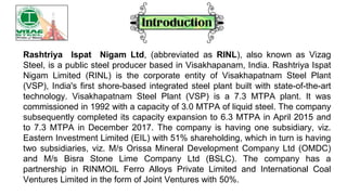
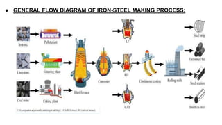
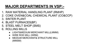
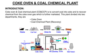
WELCOME
Rashtriya Ispat Nigam Ltd, (abbreviated as RINL), also known as Vizag
Steel, is a public steel producer based in Visakhapanam, India. Rashtriya Ispat
Nigam Limited (RINL) is the corporate entity of Visakhapatnam Steel Plant
(VSP), India's first shore-based integrated steel plant built with state-of-the-art
technology. Visakhapatnam Steel Plant (VSP) is a 7.3 MTPA plant. It was
commissioned in 1992 with a capacity of 3.0 MTPA of liquid steel. The company
subsequently completed its capacity expansion to 6.3 MTPA in April 2015 and
to 7.3 MTPA in December 2017. The company is having one subsidiary, viz.
Eastern Investment Limited (EIL) with 51% shareholding, which in turn is having
two subsidiaries, viz. M/s Orissa Mineral Development Company Ltd (OMDC)
and M/s Bisra Stone Lime Company Ltd (BSLC). The company has a
partnership in RINMOIL Ferro Alloys Private Limited and International Coal
Ventures Limited in the form of Joint Ventures with 50%.
● GENERAL FLOW DIAGRAM OF IRON-STEEL MAKING PROCESS:
MAJOR DEPARTMENTS IN VSP:-
1. RAW MATERIAL HANDLING PLANT (RMHP)
2. COKE OVEN&COAL CHEMICAL PLANT (CO&CCP)
3. SINTER PLANT
4. BLAST FURNACES(BF)
5. STEEL MELT SHOP (SMS)
6. ROLLING MILLS
● LIGHT&MEDIUM MERCHANT MILL(LMMM)
● WIRE ROD MILL (WRM)
● MEDIUM MERCHANT& STRUCTURE MILL
(MMSM)
1. RAW MATERIALS HANDLING PLANT(RMHP): RMHP is meant for
transporting materials yard/base mix yard to various process units of the
plant.
1. COKE OVEN AND COAL CHEMICAL PLANT(CO&CCP):Coke is
manufactured by heating of crushed coking coal in absence of air at a
temperature of 1100ºc and for about 16-18 hrs.
SINTER PLANT: Sinter is hard, porous ferrous material obtained by
agglomeration of iron fines, coke breeze, lime stone fines, metallurgical waste
like dust, mill scale, LD slag.
3.
BLAST FURNACE: Hot metal is produced in blast furnace, which are tall and
vertical. Raw materials are Iron Ore, Coke, Dolomite, and Limestone. It is
charged from the top and hot blast at 1100°c-1300°c. there are two B.F’s
each with a volume of 3200m3, each with 4 tap holes and with a daily
production of 9720 tons of liquid steel.
Steel Melt Shop: Steel is an alloy of iron with carbon up to 18%. Hot metal
produced in B.F contains impurities such as carbon (3.5-4.25%), silicon (0.4-
0.5%, manganese (0.3-0.4%), sulphur (0.04%max) and phosphorous
(0.14%max). to improve the quality of steel, the impurities have to be
removed by oxidation process which is done in converter shop having 3 LD
converters.
4.
5.
Rolling mills : Blooms produced in SMS-CCD do not have much application
as they are. So they are shaped into Billets, Rounds, Squares, Angles,
Channels, Wire Rods, Rein Forced Bars etc.
LMMM: LIGHT AND MEDIUM MERCHANT MILL.
WRM: WIRE ROD MILL.
MMSM: MEDIUM MERCHANT AND STRUCTURE MILL.
6.
DEPARTMENTS ALLOWTED FOR TRAINEES:-
● COKE OVEN AND COAL CHEMICAL PLANT(CO&CCP).
● UTILITIES DEPARTMENT.
● QUALITY ASSURANCE AND TECHNOLOGY
DEVELOPMENT(QA&TD).
● THERMAL POWER PLANT (TPP)
● WATER MANAGEMENT DEPARTMENT (WMD)
COKE OVEN & COAL CHEMICAL PLANT:
COKE OVEN ;
Coal Preparation Plant
Coke Oven Batteries
Coke Dry Cooling Plant
Coke Sorting Plant
Coal Chemical Plant:
Primary Gas Coolers
Ammonium Sulphate Plant
Final Gas Coolers
M.B.C
Tar Distillation
P.C.L.A
Naphthalene Fraction Crystallization
➢
▪
▪
▪
▪
▪
▪
▪
▪
▪
▪
▪
▪ Benzol Recovery
▪ Hydro Refining
▪ Extractive Distillation Unit
QUALITY ASSURANCE AND TECHNOLOGY DEPARTMENT:
▪ Coke oven & Coal chemical plant laboratory
▪ Central laboratory
▪ Mechanical biological chemical laboratory
▪ Thermal Power plant & captive power plant
➢
UTILITIES:
▪ Air Separation Plant
▪ Argon Unit
▪ Liquid Storage & Distribution
▪ Cylinder Filling Station
▪ Water Electrolysis Plant
▪ Acetylene Plant
▪ Compressor house
▪ chilled water house
➢
➢ THERMAL POWER PLANT:-
▪ OLD DM PLANT
▪ DM PLANT OF NEW EXPANSION & CAPATIVE POWER PLANT
➢ WATER MANAGEMENT DEPARTMENT:-
▪ Kanithi Balancing Reservoir (KBR)
▪ Raw water treatment plant
▪ Pump house-1
▪ Pump house-2
▪ Ultra filtration plant
Various chemicals used in water treatment process
➢what is coal?
A:Coal originated from arrested decay of
the remains of trees, masses, bushes,
plant life....on million of years.that is
readily combustible. Coal is black or
brownish-black, and has a composition
that (including inherent moisture)
consists of more than 50 percent by
weight and more than 70 percent by
volume of carbonaceous material.
COAL COKE
1.It is a primary fuel 1.It is a secondary fuel
2.It is a readily combustible black or
brownish black sedimentary rock.
2. Coke from coal is grey, hard,
sedimentary and porous. Coke is a solid
carbonaceous leftover derived from
destructive distllation of low-ash,
low-sulfur bituminous coal.
3.Coal usually contains a considerable
amount of incidental moisture,which is the
water trapped in the coal in between the
coal particles coals are usually mined wet
and may be stored wet to prevent
spontaneous combustion.
3.The volatile constituents of the coal,
induding water, coal-gas and coal-tar, are
driven off by baking in an oven without air
temperatures as high as 1,000 c (1,832 °F)
so that the fixed carbon and residual ash
are fused together.In that scene Coke has
better yield of energy as volatile
compounds have been removed
4.coal has 0.4 times greater density as
coke has.
4.coke typically has a specific gravity
between 1.85 & 1.9. It is highly porous, and
a mass of coke has 40% greater volume
than the equivalent mass of coal
COKE OVEN & COAL CHEMICAL PLANT
Coke oven & Coal chemical plant (CO&CCP) is to convert coal into coke and to recover
chemical from the coke oven gas which is further marketed. This plant divided into two
departments, they are
• Coke Oven
• Coal Chemical Plant (Recovery)
INTRODUCTION:
Coke oven is the department where coal is converted into coke and then it is cooled,
sorted then send to blast furnace. Also, the gas evolved is send to recovery. This
department is divided into 4 sections, they are:
● Coal Preparation Plant (CPP)
● Batteries
● Coke Dry Cooling Plant (CDCP)
● Coke Sorting Plant (CSP)
● COAL PREPARATION PLANT:
1.FOREIGN OBJECT SEPARATION:
a. In FOS, rotary screens are present.
b. In FOS, the top product is foreign object and bottom product is coal.
c. Other than coal it is foreign object. Coal is dropped in conveyor for the further
process.
2. MIXING BINS:
a.We have 22 mixing bins.
b.Bins are used to store the coal.
3. COAL BLENDING:
a.It is for mixing of 7 types of coal.
b.We have to blend the 7 types of different coal.
C.We blend 40% of Australia coal and 60% of Indian coal.
D.we use two types of conveyor patterns
1.odd conveyor
2.even conveyor
4.HAMMER CRUSHER:
a.It crushes the mixture of coal to reduce size for better processing.
b.It have screens were -3mm size of coal is separated and oversize coal is again
send to crusher.
5. COAL TOWER:
a.It has 24 pockets.
b.It’s storage capacity is 1000tones.
COKE OVEN BATTERIES:
● We have 5 batteries.
● Each battery consists of 67 ovens and 68 chambers.
● Oven dimensions are length-16m, height-7m and width-0.48m.
● Chamber dimensions are length-16m, height-7m , width-0.48m.
● Length of batteries is 64.8m
● Each battery consists of four cars:
● Pusher car – front side of battery.
● Charging car – top side of battery.
● Door extractor car(DE)– back side of battery
● Coke car – it is on the rail (loco car)
● Oven have 5 openings one at the front side, one at the back side and other there
on the top side .
● The charging car have 3 bins which drop the coal at front, middle of back portions
of the oven by the 3 opening on the top side of the oven.
● Bins capacity is 12tons, 8 tons and 12 tons.
● Coal is charged from pockets to charging car.
● The pusher car is at front side and its pushes the coal from discharge
● The DE car is at back side and its extracted the back door and discharge the
coke.
● First open the back side, then pushes the coke by front side by using pusher
car.
● Oven temperature is 1100^c and coke produces in 19 hours and 32 tons is
charged in oven from charging car.
● Oven products are coke and coke oven gas.
● In oven, carbonisation process takes place.
● For 32 tons of coal, 25 tons of coke and 7 tons of coke oven gas is produced.
COKE DRY & COOLING PLANT:
● Each CDCP consists of 4 chambers.
● We have 5 CDCP.
● Each chamber capacity is 200 tons.
● 8 buckets are in one chamber.
● Height of chamber is 40m.
● Buckets of chamber are lifted by slings.
● Time taken for this process is 6hrs.
● From top, coke is send at 1100^c and from
bottom, nitrogen gas is send at 120^c.
● The heated nitrogen gas is send to boiler and
used for power generation.
COKE SORTING PLANT:
● We have hammer crusher to reduces the coke size.
● It has 3 screens for separation.
● 70 to 80mm size coke for blast furnace – bf coke.
● 25mm size coke for sinter plant – sinter coke.
● 0mm size – coke breeze.
COKE
HAMMER CRUSHER
SCREEN SCREEN SCREEN
BF COKE
(75MM)
NUT COKE
(25MM)
COKE BREEZE
(SOLD BY PLANT)
BF COKE
NUT COKE
COKE BREEZE
COAL CHEMICAL PLANT
Introduction:
The coke oven gas which is a mixture of harmful gas is not released directly into
atmosphere.
That is why it is sent to recovery section. Coal Chemical Plant includes:
● Primary Gas Cooler (PGC)
● Electrostatic precipitator (ESP)
● Exhauster
● Ammonium Sulphate Plant (ASP)
● Final Gas Cooler (FGC)
● Tar Distillation Plant (TDP)
● Benzol Plant
PROCESS:
GAS COLLECTING MEDIUM(GCM):
● Coke oven is collected at 800^c from oven.
● We use flushing liquor to cool the gas up to 80^c.
● It is a direct contact cooling process.
FLOW DIAGRAM OF COAL CHEMICAL PLANT:-
PRIMARY GAS COOLER:-
a There are 15 PGC are present.
b It is a indirect contact cooling type.
C.It has 2 sections
1.Service water section
2.Chilled water section
d. To remove tar, naphtha from gas, tar flushing is done in service water
section.
e By gravity tar will settled down.
The tar is then collected at the bottom in seal pot. The CO gas from the bottom
of the PGC is fed to the electrostatic precipitator.
Gas temperature before PGC 80-95°c
Gas temperature after PGC 27-30°c
Service water inlet temperature 32-33°c
Service water outlet
temperature
43°c
Chilled water inlet temperature 11-12°c
Chilled water outlet temperature 20°c
Total number of tubes 409
3.ELECTROSTATIC PRECIPITATOR(ESP):
a.There are 8 ESP.
b.Inlet from bottom, outlet from top.
c.It is use only for gas cleaning.
c.It has high voltage electrons to remove impurities.
d.Impurities are settled to bottom by gravity and collected in seal pot.
e.voltage of 70KV & Capacity of 30,000 Nm3/hr.
CONDENSATE PUMP HOUSE:-
Flushing liquor separated from the separators is fed to the condensate pump
house. This consists of decanters and storage tanks. The tar and flushing liquor
collected from the PGC and ESP sent to the decanters.
EXHAUSTER:-
These are centrifugal fans necessary to suck the gas from the batteries itself
and to drive the gas from batteries to various plants like ASP (Ammonium
sulphate plant), Benzene recovery and finally to the main header of the coke
oven gas. The pressure at the suction side of the exhauster I'd -250mm of water
column and the discharge side is +2500mm of water column. Due to
compression of gas in the exhauster the temperature of the gas will be
increased from 30 to 600C.Capacity of 67,000-76000Nm3/hr and power of 1200
KW.Maximum suction at inlet 500mmwc Maximum pressure at delivery
2700mmwc.
AMMONIUM SULPHATE PLANT (PUSHKALA FERTILIZER):-
● Gas from exhauster is send to pre heater.
● In pre heater it heated up to 60-65^c . If temperature is less than it may have
chance form salts.
● Saturator is always maintained with acid bath called mother liquor, which
contained 4-5% of sulfuric acid.
● Mother liquor is consists of
1.Hot water
2.H2so4
3.Ammonium sulphate(AS).
4.Ammonium bi-sulphate(ABS).
● There are 3 saturators are present in ASP.
● The CO gas enters through bubbler hood which is dipped in the bath. The gas
rises through the mother liquor. During this period, the ammonia present in the
gas reacts with the sulfuric acid in the liquor.
NH3 + H2SO4 NH4 (HSO4)
NH4 (HSO4) + NH3 (NH4)2 SO4
● the gas from saturator is send to acid trap to remove sulfur and ammonium
sulphate is present.
● In acid trap, high density liquid is collected from bottom and low density gas
is passed to next section.
● In CR tank, yellowish ammonium sulphate is collected and send to centrifuge
crystallizer where liquid and crystals are separated.
● In centrifuge crystallizer, hot water is send to melt the tar crystals in liquid.
● The liquid is send back to saturator.
● The crystals are dried in driers and then send to bagging by conveyor.
● In saturator mother liquor(ML) gas, nitrogen and H2so4 are reacted with
each other to form ammonium bi-sulphate.
● Nitrogen is send to saturator because its a inert gas. It send to increase this
rate of process.
● First(ABS) is formed and collected in circulating tank.
● Again (ABS) is used to saturated to react and form ammonium sulphate.
● The liquor ammonium sulphate is send to crystal receiver(CR) tank.
FINAL GAS COOLER (FGC):-
Coke oven gas after ammonia recovery enters into FGC. Here remaining fraction
of naphthalene and benzol is removed from the CO gas.
This section contains:
• Final Gas Cooler
• Gas Pre cooler
• Two scrubbers
Process Description:
Final Gas Cooler:
Coke oven gas consists of 0.8 – 1.1.2 mg/Lit of naphthalene particles are
removed by spraying tar.
Temperature at the bottom of FGC 50 – 60 0C
Naphthalene in CO gas after FGC 0.4 g/Nm3
FGC tar temperature 80 – 90 0C
Specific gravity of FGC tar moisture 5 %
Gas Pre-Cooler:
The gas at 30-350C is fed to the pre-cooler, which is indirect contact cooler. The gas
is cooled
by chilled water (1500C), which passes through the tubes. The gas is cooled to 25-
270C so that any particles condensed are received in the seal pot.
SCRUBBER:
● Scrubbers are long towers consisting of aluminum packing or
● wooden sheets provided with three layers.
● The CO gas from the gas pre-coolers is sent to the first Benzol
scrubber at the bottom. Solar
● oil or de-benzolised oil is used for the scrubbing the gas to
recover the benzol. Large amount of benzol is absorbed in
the first scrubber
● At the bottom of the first scrubber a certain level of de-
benzolised oil is maintained.
● CO gas from the top of the first scrubber is fed to the bottom of the second
scrubber in which it comes to contact with fresh de-benzolised oil, which
removes the trace of benzol remaining in the gas
● Solar oil is added if concentrated oil quantity is decrease in DBO.
● Bo will collected in BO tank.
● Benzolised oil is send to BDP(Benzol distillation plant).
BENZOL PLANT:-
Benzol plant is provided in order to produce pure benzene, toluene and solvent naphtha.
Benzol plant consisting of three sections
• Benzol distillation plant
• Hydro refining unit
• Extractive distillation unit
Crude benzol recover from the coke gas is fed to benzol distillation plant. Various
chemicals in the benzol are recovered by distillation.
Benzol Distillation Plant (BDP):
In BDP the benzolised oil from final absorption is pumped to the storage tanks of the
benzol distillation. The BO is then stripped of with steam to get the crude benzol and DBO.
This DBO is again pumped to benzol recovery section. Makeup solar oil is added
continuously to compensate for the losses in the equipment. The BO is initially preheated
in three preheaters, which are shell and tube heat exchangers. Pre heating is first done in
oil dephlegmators, oil-oil heat exchangers and finally in steam pre heaters. The
temperature is slowly decreased in order to prevent chemical decomposition of BO. The
temperature of the BO fed to the stripping column is about 130-1350C.
TUBE SIDE SHELL SIDE
Oil dephlegmator Vapours of stripping column
Oil-Oil exchangers Steam pre-heaters
Steam pre-heaters Medium pressure steam
Here the BO reacted with live steam in stripping column and then the top product
comes into crude benzol tank and bottom product is used as heating agent in
preheater. From CB tank the light denser items goes to HRED.
CRUDE BENZOL COLUMNS:-
where the crude benzol is separated to
heavy crude benzol (HCB – used as
furnace oil) and light crude benzol (LCB-
contains fractions of benzene,toluene,
xylene).This column consists of 16 bubble
cap trays.Simple distillation is carried out in
this column.The bottom product of the
CB – I which mainly contains HCB with
small amounts of LCB is fed to CB-ll.
To recover the CB – I the liquid is to be distilled. The CB – I vapours obtained
from the top of the CB –II is fed to CB – I column as reflux. The bottom product
obtained from CB – II is called as HCB.(CB-l:LCB,CB-ll:HCB)
TAR DISTILLATION PLANT
Composition of coal tar coming to TDS:
● Light oil 0.5%
● Phenol fraction 1-1.5 %
● Naphthalene. 5-6 %
● Wash oil 8-9%
● Anthracene oil 18-19 %
● Moisture 5-6 %
● Pitch 55-60%
Process Description:
The tar from the condensate pump house is fed to the tar and oil storage of TDP.
The tar to the TDS is fed from the tar and oil storage tanks. This tar contains 5 %
moisture, which can be removed in the decanters.
DISTILLATION COLUMN:-
Mixed oil vapours from the top of the second stage evaporator are fed to the third
tray of the fractionating column at a temperature of 360 – 3800C. As the vapours
rises to the top of the column different fractions are obtained from different trays.
Initially vapours enter at about 360 – 4000C. Pure light oil is supplied as reflux to
the top plate rectification column to maintain top temperature of the column.
NAPHTHALENE ANTHRACENE FRACTION COLUMN
PROCESS DISCRIPTION:-
The naptha oil from TDS purity of
about 70-80% sent to drum crystallizer after storing
in tank with temperature 60-65°c.Drum crystallizer
consists of a rollers inside & contains 160 blades
fixed with drum.oil is sent to drum & contains water
to sprinkled inside the roller then roller
cooled,naptha oil is have a tendency to form solid
that,s that's why it touches cooled roller it form a
layer& it removed by using blades powdered
naptha sent to mixer using screw conveyor in drum
crystallizer.from mixture to hydraulic press powder
to be feded.In hydraulic press powder is to be
pressed &by using filters pressed oil to be removed
about 6% purity and pressed cake sent to bagging
by chute outlet.pressed oil sent to storage tank.
Introduction:
Excess flushing liquor & toxic effluents generated in CO&CCP need to be treated to
comply with APPCB (Andhra Pradesh State Pollution Control Board) norms before
being disposed to sea. Effluents generated in coke ovens contain a lot of harmful
pollutants that disturb the harmony of environment in and around the steel plant.
Source of Effluents:
Various sources of polluted water enter into MBC plant for treatment purpose.
• Excess flushing liquor from battery (W1)
• Blow down water from pump house 18 in final gas coolers (W2)
• Spillage generated in benzol distillation plant (w3) will be around 5m3/hr.
• Spillage generated in tar plant (occasionally)
• Effluent collected in phenol faecal pump houses (pumped to decanter section)
MECHANICAL BIOLOGICAL CHEMICAL TREATMENT PLANT (MBC)
Major Pollutants in Coke Oven Effluent Water:
• Phenols
• Rhodanides (Thiocyanides)
• Cyanides
• Ammonia
• Oil and grease
• Mixed liquor suspended solids
AMMONIA COLUMN:-
The Ammonia column consists of 24
bubble cap trays. 40% of liquor level
is maintained in the column. Steam is
injected at the bottom by steam coils.
The purpose of steam is to supply
the necessary heat for distillation. As
the liquor is distilled, free ammonia
present in the flushing liquor evolves
and rises to the top of the column.
Flash Unit:
Flash unit (FU) is used for cooling of effluent delivered to MBC after treatment in
ammonia stripping columns. Effluent in flash unit is cooled by means of flashing in
vacuum .Hot effluent at a temperature 80 – 85°C is cooled to 65 – 70°C.
Heat Exchangers:
Outlet water from flash unit enters a series of heat exchangers for further reduction of
temperature.Three different sets of heat exchangers are in use in MBC plant.
● Shell and tube heat exchanger
● Pipe in pipe heat exchanger
● Twin pipe in pipe type heat exchanger
In the twin pipe in pipe type heat exchangers
cooling medium is industrial circulating water.
Tar Settling Tanks:
Effluent water from pre-aeration tanks is distributed into parallel arranged 5 tar
settling tanks for treatment from course dispersive insoluble impurities including
heavy tar and oil.Capacity of each tar settling tank: 230 m3
Phenolic Water Collecting Tanks:
Effluent water from TST is the input for phenol collecting tanks. Ferrous Sulphate is
added to this water for the decrease of effluent toxicity and increase in the efficiency
of treatment of the same from oil. Mainly ferrous sulphate converts volatile cyanides
into non-volatile and nontoxic Ferro-cyanides.
OIL FLOATATORS:
Effluent water from phenol collecting tanks enters into oil flotation tanks through
pressure tanks.Flotation method is based on the ability of suspended solids
molecularly to stick together with finely dispersed bubbles of air and then float up as
oily foam.From flotation tanks, heavy tar and oil effluent enters into an intermediate
tank. From the intermediate collector, tar and oil are separated and stored in two
different storage tanks. Treated effluent water goes to equalizing/averaging tanks.
EQUALIZING TANKS:-
From oil flotation tanks clarified effluent enters into two sections (E1/E2) of
averaging tank by gravity where it mixed and averaged in temperature,contaminating
components concentration and pH as a result of mixing by compressed air supplied
from air-blowers.
First Stage Aero Tanks:
In aeration tanks of the 1st stage (A11, A12, A13, A14 and A15) partial treatment of
phenols by culture of phenol destructive bacteria (Pseudomonas Putida) is carried
out. By these bacteria, the phenol present in effluent gets destructed into carbon
dioxide and water in the presence of air (aerobic).
C6H5OH +7.O2 - 3H2O + 6.CO2
Second Stage Aero Tanks:
At the second stage effluent is treated by mixed culture (Thiobacillus) containing
main types of bacteria destructing coke plant effluent contaminants. Oxidation of
cyanides and rhodanides in the form of ammonia dissolved impurities.
NH4CNS +2.O2 +2.H2O - (NH4)2SO4 + CO2
2NH4CN + O2 + 4.H2O - 2(NH4)2CO3
Third Stage Aero Tanks:
At the third stage the whole effluent treated from ammonia as well as small amounts of
phenols, Thiocyanides. For this ammonal destruction Nitrosomonas, Nitrobacteria are
added which forms nitrites and nitrates respectively. To ensure nitrification process
working solution of alkali (soda ash) is supplied by pump into aeration tanks of third
stage. Oxidation of ammonium nitrogen nitrification is performed by bacteria being
aerobic autotrophs for vital functions of which oxygen and inorganic carbon in the form
of carbon dioxide is necessary.
Fourth Stage Aeration Tanks:
In this aeration tanks are designed for chemical oxygen demand and
biological oxygen demand and increase of treatment degree from ammonia,phenols
and nitrates after the third stage.The activated carbon absorbs all chemicals or
reacts with chemicals and forms as a anions.another is added as a cation for
maintaining pH value we are added soda ash.
Tank-17:-
In this we are added alum as as coagulant for sedimentation of TSS and also
added the flocculent for formation of flocks after the formation of flocks it will sent to
clarifiers and separated that TSS.
PARAMETER NORMS
V-phenol 1PPM(MAX)
Cyanide 0.2PPM(MAX)
Rhodanides 10PPM(MAX)
Ammonical nitrogen 50PPM(MAX)
H2S 10PPM(MAX)
COD 250PPM(MAX)
BOD 30PPM(MAX)
PH 6-9
TSS 100PPM(MAX)
O&G 10PPM(/MAX)
● QUALITY OF MBC WATER OUTLET:-
UTILITIES DEPARTMENT
ROLE OF UTILITIES:-
Utilities department produces and makes available for distribution of the following
products.
Products Produced & distributed:
Oxygen gas & liquid
Nitrogen gas & liquid
> Argon gas & liquid
> Compressed air, Industrial grade dry air,
> Chilled water
Produced & distributed:
> Dissolved Acetylene gas
> LPG
DRY AIR:-The air free from moisture is known as dry air.
INSTRUMENTAL AIR:---The purified and highly compressed air is known as
instrumental air.
CHILLED WATER:---The water whose temperature vary from 6-12°c is called
chilled water.
AIR SEPARATION PLANT
● Atmospheric air is filtered and compressed in air compressors to
6.4Kg/cm2.
● Compressed air is cooled to 10°C with the help of refrigeration unit and
air water tower.
● The compressed and pre-cooled air is purified in adsorber beds with
adsorbents activated alumina and molecular sieves to remove moisture
& carbon dioxide and impurities.
● It is then further cooled using expanders and heat exchangers to the
temperature of- 178°C.
● It is then distilled in the cryogenic distillation in the temperature range of
-175 to -196 degrees C where fractions of liquid nitrogen, liquid
oxygen,liquid argon, gaseous oXygen and gaseous nitrogen are
produced.The gaseous oxygen and nitrogen are compressed in
separate compressors and sent to their consuming sections.
● The Liquid O2, N2, and Ar are stored in storage tanks, from where the
liquids are sold/ vaporized to fill cylinders/ used for backup supply.
● The cold or refrigeration required for the system is generated by the expansion
of high pressure air to low pressure through a set of reducing valves and
expansion turbine.
● An intermediate product from the Distillation column,crude argon containing 10%
Argon is enriched to 90% argon in a seperate distillation column.
● Hydrogen is injected for purification of Argon by removing oxygen in presence of
de-oxo catalyst.the formed water separated & adsorption system and nitrogen is
separated by cryogenic distillation system.
● Safety point is cold burns while handling cryogenic liquids.
The “cryogenic distillation” is a process of separation of gaseous mixture, using simple
distillation, at high pressure and low temperature.
COMPRESSOR HOUSE-2
INTRODUCTION:-
Plant air is required for the operation of pneumatic devices, pneumatic tools and for
general purpose.dry air is required for the operation of instruments & controls.To meet
the above requirements 4no’s of centrifugal compressors (15000Nm3/hr capacity each)
are installed.
CHILLED WATER PLANT
Chilled water required for use in ventilation and air conditioning systems in the areas
such as office rooms, electrical control rooms etc. These plants have 12 units each
with a capacity to cool 180m3/hr of water from 16°C to 7°C.
Vizag Steel Plant contains 4 Chilled Water plants. They are
● Chilled Water Plant-I (located at Coke Ovens)
● Chilled Water Plant-II (located at Power plant area)
● Chilled Water Plant-III (located at Mills)
● Chilled Water Plant-IV (located at Central Laboratory)
REFRIGERANT:- A refrigerant is a substance used in a heat cycle to transfer heat
from one area and remove it to another .
evaporator in which it absorbs heat from water pumped from warm water tank.
Evaporated refrigerant again recycled to compressor. The chilled water having
temperature 6-7°C is supplied to various departments where chilled water is used.
REFRIGERANT:- A refrigerant is a substance used in a heat cycle to transfer heat
from one area and remove it to another .
LPG PLANT
Process Description:
LPG plant involves three processes, they are Decantation, Vaporization and
Pressure reducing station.
DECANTATION:-
LPG from tankers is pressurized and send to bullets with some pressure nearly
6kg/cm2. LPG tankers contain both vapor and liquid, liquid is pumped and vapor is
compressed and send to bullets to maintain bullet pressure. The vapours present in
the bullets or in unloading tanks are send to pressure reducing station. The liquid
LPG from bullets send to vaporization
● FLOW DIAGRAM OF LPG PLANT:-
VAPOURIZER:-
The liquid LPG from bullets passes into the coils of the VAPOURIZER, through pipe
line system.In the VAPOURIZER,the coils are immersed in that hot water at 80-95°c
temperature.due to heat exchange between hot water and liquid LPG.liquid LPG
attains it's boiling point and VAPOURIZER.
ENTRAINMENT SEPARATOR:-
The vapours of LPG formed in VAPOURIZER are sent to the entrainment separator to
remove if any dirt or dust is present based on density difference and purify LPG
vapours.
PRESSURE REDUCTION STATION:-
The purified LPG vapours sent to PRS to reduce or adjust the pressure of the LPG
vapours according to consumers requirement and was sent to SMS-1 & SMS-2 for
gas cutting.
QUALITY ASSURANCE & TECHNOLOGY DEPARTMENT
Introduction:
The QA & TD dept. has been set up to take care of activities pertaining to Quality
Control of Raw Materials, Semi finished products and finished products. The QA & TD
labs are provided at major department like CO&CCP, SP, BF, SMS, Rolling Mills etc.,
in addition to Central Laboratory. The Department monitors the process parameters
for production of quality products. QA & TD carries out analysis, testing and final
inspection including spark testing of finished products and assigns grades to them.
QA & TD is categorized into
● CENTRAL LABORATORY
● COCCP LABORATORY
● POWER PLANT LABORATORY
CENTRAL LABORATORY:
● Water Lab
● Oil Lab
● Microbiology Lab
● Wet Lab
WATER LAB:
This lab conducts test for drinking water, effluent water and recirculating water.
Drinking water is to be tested as many impurities and elements would be present in the
water that may affect our health.
● PH test
● Ammonical nitrogen test
● Total suspended solids
● Phenols test
● COD (chemical oxygen demand)
● BOD (Biological oxygen demand)
● DO (Dissolved oxygen)
DETERMINATION OF PH TEST:-
● Take the sample in a beaker
● Clean the electrode with DM water and wipe it with tissue paper
● Then ON the PH meter
● Place the electrode in the sample
● And then note down the PH reading
● Again clean the electrode with DM water and place it in buffer.
DETERMINATION OF AMMONICAL NITROGEN TEST:-
● Take the sample in a beaker
● Clean the electrode and stirrer then ON the meter
● Keep the electrode in the sample and switch on the stirrer
● Make sure that the stirrer doesn't touch the walls of the beaker
● Now add 1.5ml of ammonia buffer
● Wait until ready is displayed on place of stabilizing
● Then note down the reading
● After clean the electrode with DM water.
DETERMINATION OF TOTAL SUSPENDED SOLIDS:-
● Take watsman filter papers and keep it in oven for 30 mins at 100°c
● Then keep those filter paper in dessicator for 25 mins
● Now note down the initial weight of filter paper
● Place on the watch glass and give numberings on four sides
● Arrange the apparatus as shown
● Wet the filter paper and add 100 ml of sample
● ON the vaccum generator which is connected to the apparatus due to
auction water passes through the filter,all the suspended solids are stick to
the filter paper.
● Now take the filter paper and do the same procedure for all the samples.
● Now keep the filter paper in oven for one hour and 30 min in dessicator
● Take the final weight of filter paper
CALCULATIONS:-
TSS=Final weight-initial weight/100x10^6
DETERMINATION OF PHENOLS TEST:-
● Take a round bottomed flask.
● Add 350ml of DM water and 100ml of sample water and stir it
● Now add 10 ml of copper sulphate and add 2 ml of orthopurs acid
● Set the Distillation apparatus with round bottomed flask
● Wait until 250 ml of distillate is collected.
● And then add 4ml of ammonium hydroxide
● 1.5ml of phosphate buffer
● 3ml of potassium ferricyanide
● 3ml of amino pyradine
Now leave it for 10 mins
● If yellow colour appears it means it doesn't contain phenols.other than yellow it
contains phenols
Normal range of phenols = 1ppm
Place the sample in uv spectrometer via cuvoid
DETERMINATION OF COD:-
● Take the test tube and add 2.5ml of sample and 2 ml of blank
● Now add 1.5 ml of k2cr2o7 (potassium di-chromate) this is added to know the
level of oxygen
● Add 3.5ml of conc.H2SO4+Agso4 to it
● Mix the solution
● Now keep the test tube in COD digestor for 2 hours at 150°c
● Here acid digestion takes place i.e, break down the molecules takes place in COD
digestor
● Add 2 drops of ferrion indicator
● Now transfer it into 25ml conical flask and titrate it against ferrous ammonium sulphate
● The colour from yellow changes to dirty green then to sea green and finally to reddish
colour
FORMULA:-
Blank-titrate value x 8000 X 0.1 / 2.5
2.5 is the volume of sample taken
0.1 is the normality of ferrous ammonium sulphate
8 X 1000 atomic No. of oxygen
DETERMINATION OF DISSOLVED OXYGEN:-
● This test is conducted for various water samples
● Norm (4-6) if DO is less than 4 the aquatic life can't survive
PROCEDURE
● Take sample in a glass bottle
● And ON the DO-METER
● clean the electrode with DM water and wipe it cleanly
● Dip the electrode in the sample
● Set the stirrer RPM
● And then DO. Value is visible on the display
DETERMINATION OF TOTAL HARDNESS:-
● 50ml of sample water is taken in a 250 ml conical flask and 5 ml of
(NH3-NH4CL)buffer solution and add 2-3 drops of EBT indicates the
solution is now titrated against standardized EDTA solution.
● The end point is indicated by the colour changes from wine red to blue
CALCULATION:-
RUN DOWN X 1000 / Volume of sample(ml)
DETERMINATION OF PHOSPHATE:-
● 5ml of sample is taken
● Add 17ml of DM water
● Add 1ml of 2% citric acid
● Add 1ml of 2:12 metol
● Add 1ml of 5% ammonium molybdate
● Wait for 15 mins and test in uv spectrometer via cuvette
DETERMINATION OF SILICA:
● Take 25ml of sample in a test tube
● To this add 1 ml of ammonium molybdate
● Wait for 5mins
● Then add 2ml of 5% oxalic acid
● Add 1ml of 2:12 metol
● Wait for 5mins and measure the absorbance in uv-visible spectrometer.
CO&CCP(QA&TD)
PROXIMATE ANALYSIS OF COAL:-
● Moisture content
● Volatile matter
● Ash content
● Fixed carbon
MOISTURE CONTENT:-
● A cleaned,dried and cooled moisture tube is weighted as W1. Sample of weigh
W2 is taken in a tube the tube is kept in a drying oven at a temp of 100°c for 1
hour.
● Take the tube outside and keep it in dessicator unit it cools.
%AM = (W1+W2) - W3 / W2 x 100
DETERMINATION OF VOLATILE MATTER:-
● The determination of VM for coal,coke, Petroleum coke,graphite
flakes is done using calibrated muffle furnace,silica crucible.
● A cleaned,dried and cooled silica crucible is taken and weighted as
w1 sample weight is noted as W2.
● Crucible is kept in a muffle Furnace at a temp of 950°c for 7mins.
● then the crucible is placed in a dessicator.after crucible is weighted as
W3.
%(VM+AM) = (W1+W2) - W3 / W2 x 100
ASH CONTENT:-
● Crucible is weighted and noted as W1 the sample is taken and
weighted as W2.
● Crucible is kept in a muffle Furnace at a temp of 500°c for 2 mins then
raise temp of muffle Furnace to 815°c for 1 ½ hour.
● After cooling the crucible along with ash is weighted as W3.
% ASH CONTENT = (W3 - W1) / W2 x 100
FIXED CARBON :-
%FC = 100 - (%AM+%VM+%ASH)
GAS CHROMATOGRAPHY:-
Coke oven gas,blast furnace gas,chamber (CDCP), gas are analysed.Here we find
hydrogen,methane, carbon dioxide,carbon monoxide,oxygen, Nitrogen.
PROCEDURE:-
● The 0.1mm of sample is injected and due to high temperature (200°c) inside the
oven the liquid will convert into gas.that gas is passed through column with the
help of carrier gas like H2,N2 from column gas is travel to FID(flame ionization
detector) here(O2 Is support continuously the flame will lights)
● The CHROMATOGRAPHY value/purity is visible on computer.
THERMAL POWER PLANT LABORATORY
CPP laboratory (Captive power plant):
This is an alternative power plant which was introduced recently, have a capacity of 180
Mwe. This power uses blast furnace and coke oven gas as the fuel in the boiler. This
power plant uses total wastewater which is generated in the steel plant. This power
plant has a special water demineralization plant in which the water first goes through
ultrafiltration-RO filtration-then to demineralization.
Tests done for DM water are same in both the labs . They are :
● P-alkalinity
● M-alkalinity
● Total hardness
● Calcium hardness
● Magnesium hardness
● Chloride estimation
● Silicon test
● Phosphate’s test
● SO4 test
DETERMINATION OF P&M ALKANITY:-
REAGENTS USED:-: 1. Standard H2SO4 0.02 N
2. Phenolphthalein Indicator
3. Methyl Orange Indicator
Procedure :
● Take 25 (or) 50 ml sample in conical flask & add 2-3 drops of
phenolphthalein Indicator.
● If pink colour develops titrate with 0.02 N H2SO4 till the pink colour
disappears .
● If pH is 8.3 ,then note the volume of H2SO4 required (A)
● Add 2-3 drops of Methyl Orange indicator to the same flask & continue
titration, note the value of
● Sulphuric acid used(B) till pH falls to 4.5 (or) Orange yellow colour change
to Orange Red.
● In case , pink colour does not appear addition of phenolphthalein continue
to do test for MAlkalinity
Calculate total ‘M’ &’ P ‘ Alkalinity as follows & express in mg & CaCO3 / litre.
Calculation :
● P-Alkanity = (A x 1000) / ml of sample
● M-Alkanity = (B x 1000) / ml of sample
● Total ALKANITY = (A-B) x 1000 / ml of sample
DETERMINATION OF SILICON CONTENT:-
CHEMICALS USED:-1. 5% Ammonium Molybdate
2. 5% Oxalic acid
3. 2:21 Metol
PROCEDURE:-
● Take 100 ml volume of sample in test tube.
● Now add 5% Ammonium Molybdate of 4 ml then green colour develops ,wait for
5 minutes.
● Add 4 ml of 5% Oxalic acid only in drum samples in order to neutralize
phosphate content & 1 ml of metol ,allow it to settle for 15 minutes & then check
the concentration of samples in spectrophotometer at wavelength of 90 nm.
CALCULATION:-
Silica content = Factor × absorbance (factor is 2.79)
DETERMINATION OF SULPHUR CONTENT:-
CHEMICALS USED:-1. Conditioning agent
2. Barium Chloride powder
PROCEDURE:-
● Take 25 ml of sample & dilute it to 4 times i.e., make up to 100 ml
● Then take this sample into test tube up to marked level on rest tube
● Now add 1 ml of Conditioning agent & pinch of Barium Chloride powder such
white colour develops.
● Now, Check the concentration of sulphate in samples & note down the
corresponding values at 83-85 nm of wavelength using HACH meter on which the
values are displayed on screen.
DETERMINATION OF AMMONIA CONTENT:-
CHEMICALS USED:-1. Sodium Potassium Tatrate
2. Nesler’s Reagent
PROCEDURE:-
● Take 50 ml of CEP sample in conical flask.
● Then add 3 ml of Sodium Potassium Tatrate and 1 ml of Nesler’s reagent to
sample.
● Then, note the NH3 concentration using HACH meter at 31 nm wavelength & note
the corresponding values.
DETERMINATION OF HYDRAZINE :-
CHEMICALS USED:-1. 1:9 HCl
2. Dimab
PROCEDURE:-
● Take 50 ml of feed sample in conical flask Then add 2 ml of 1:9 HCl & 2 ml of
DIMAB (Di Methyl – Amino Benzaldehyde) reagent to sample.
● Note the Hydrazine (N2H4) Concentration using HACH meter at 31 nm
wavelength and note the corresponding values
● The phosphate content procedure is same as we do in CO & CPP lab and the
● test for hardness is same as in water lab.
DETERMINATION OF CALICIUM HARDNESS:-
CHEMICALS USED :- 1.4% NAOH
2.P&R INDICATOR
3.EDTA
PROCEDURE:-
Take the 50 ml sample and add 1 ml 4% NAOH to raise the PH to 10 and pinch of
P&R indicator.Then titrate immediately with EDTA.Till the pink colour changes to
purple colour.
CALCIUM HARDNESS = TITRATION VALUE × 20
THERMAL POWER PLANT
INTRODUCTION:-
Importance of DM water to our Visakhapatnam Steel plant: Without DM water, we
cannot think of a Boiler, Without a Boiler, there will not be any steam turbine and
as such no Power generation. The most important factor to be considered before
sending DM water to the Boilers is the Silica content which should not exceed
0.02ppm. If it exceeds this limit in superheated steam, it will start pitting on turbine
blades and spoils the turbine blades.
Flash mixer
{ alum solution + ferric chloride + polyelctrolyte}
Pressure sand filter
Activated carbon filter
Stream flow diagram
Self cleaning filter
Ultra filtration
Micro cartridge filter
Reverse osmosis
Degasser tower
Cation exchanger
Anion exchanger
Mixed bed exchanger
Dm storage tank
RAW WATER DM WATER
1. Ph 8 - 8.5 6.5 - 7.2
2. Conductivity 350µmho/cm 0.5 µ mho/cm
3. Ca hardness
as CaCO3
50 ppm Nil
4. Mg hardness
as CaCO3
60 ppm Nil
5. Total hardness
as CaCO3
110 ppm Nil
6. P-alkalinity
(phenaphthalene
)
0 Nil
7. M-alkalinity 130 ppm Nil
8. Silica (SiO2) as CaCO3 10 ppm less than 0.02
ppm
9. Turbidity 12 ppm Nil
10. Sulphates as CaCO3 34 ppm Nil
WATER MANAGEMENT DEPARTMENT
Kanithi Balancing Reservoir:
Raw Water to visakhapatnam steel plant is supplied by visakhapatnam
industrial water supply company limited (VIWSCO) on chargeable and is
supplied Yeleswaram Reservoir (located in East Godavari District at about
153 km from steel plant).
18 MLD Drinking water Treatment Plant:
18 MLD Treatment Plant: It receives raw water through the two (CI & MS) pipes
from IPH of KBR-1 and treats it to make drinking water.
9 MLD Sewage Water Treatment Plant:
9 MLD Capacity Sewage Treatment Plant: it receive Sewage (.e. from kitchen, toilet,
bathroom) generated in the township areas Sewage is pumped from its raw sewage
sump to 04 no's aerators. From the aerators the water Flows to clarifier. The clear
water from the clarifier and after disinfection by commercial grade Sodium hypo
chlorite, flows to balancing tank for onward pumping of this secondary treated Sewage
water to Ultra Filtration Plant (UFP) which is located inside the plant at RWTP zone and
About 4 KMs from 9 MLD plant. At UFP, the secondary treated sewage water is further
treated to Be used in recirculating water systems.
PUMP HOUSE-1:-
● The raw water from the kbr flowing into
the PH-1 . In this the plant the raw water
treated as a drinking water.
● The water for drinking and fire fightings
purposes is distributed throughout the
plant by Underground pipe line networks.
PUMP HOUSE - 2:-
ULTRA FILTRATION PLANT:-
THANK YOU

Untitled presentation-steelplant information

  • 2.
  • 4.
    Rashtriya Ispat NigamLtd, (abbreviated as RINL), also known as Vizag Steel, is a public steel producer based in Visakhapanam, India. Rashtriya Ispat Nigam Limited (RINL) is the corporate entity of Visakhapatnam Steel Plant (VSP), India's first shore-based integrated steel plant built with state-of-the-art technology. Visakhapatnam Steel Plant (VSP) is a 7.3 MTPA plant. It was commissioned in 1992 with a capacity of 3.0 MTPA of liquid steel. The company subsequently completed its capacity expansion to 6.3 MTPA in April 2015 and to 7.3 MTPA in December 2017. The company is having one subsidiary, viz. Eastern Investment Limited (EIL) with 51% shareholding, which in turn is having two subsidiaries, viz. M/s Orissa Mineral Development Company Ltd (OMDC) and M/s Bisra Stone Lime Company Ltd (BSLC). The company has a partnership in RINMOIL Ferro Alloys Private Limited and International Coal Ventures Limited in the form of Joint Ventures with 50%.
  • 5.
    ● GENERAL FLOWDIAGRAM OF IRON-STEEL MAKING PROCESS:
  • 6.
    MAJOR DEPARTMENTS INVSP:- 1. RAW MATERIAL HANDLING PLANT (RMHP) 2. COKE OVEN&COAL CHEMICAL PLANT (CO&CCP) 3. SINTER PLANT 4. BLAST FURNACES(BF) 5. STEEL MELT SHOP (SMS) 6. ROLLING MILLS ● LIGHT&MEDIUM MERCHANT MILL(LMMM) ● WIRE ROD MILL (WRM) ● MEDIUM MERCHANT& STRUCTURE MILL (MMSM)
  • 7.
    1. RAW MATERIALSHANDLING PLANT(RMHP): RMHP is meant for transporting materials yard/base mix yard to various process units of the plant. 1. COKE OVEN AND COAL CHEMICAL PLANT(CO&CCP):Coke is manufactured by heating of crushed coking coal in absence of air at a temperature of 1100ºc and for about 16-18 hrs. SINTER PLANT: Sinter is hard, porous ferrous material obtained by agglomeration of iron fines, coke breeze, lime stone fines, metallurgical waste like dust, mill scale, LD slag. 3.
  • 8.
    BLAST FURNACE: Hotmetal is produced in blast furnace, which are tall and vertical. Raw materials are Iron Ore, Coke, Dolomite, and Limestone. It is charged from the top and hot blast at 1100°c-1300°c. there are two B.F’s each with a volume of 3200m3, each with 4 tap holes and with a daily production of 9720 tons of liquid steel. Steel Melt Shop: Steel is an alloy of iron with carbon up to 18%. Hot metal produced in B.F contains impurities such as carbon (3.5-4.25%), silicon (0.4- 0.5%, manganese (0.3-0.4%), sulphur (0.04%max) and phosphorous (0.14%max). to improve the quality of steel, the impurities have to be removed by oxidation process which is done in converter shop having 3 LD converters. 4. 5. Rolling mills : Blooms produced in SMS-CCD do not have much application as they are. So they are shaped into Billets, Rounds, Squares, Angles, Channels, Wire Rods, Rein Forced Bars etc. LMMM: LIGHT AND MEDIUM MERCHANT MILL. WRM: WIRE ROD MILL. MMSM: MEDIUM MERCHANT AND STRUCTURE MILL. 6.
  • 9.
    DEPARTMENTS ALLOWTED FORTRAINEES:- ● COKE OVEN AND COAL CHEMICAL PLANT(CO&CCP). ● UTILITIES DEPARTMENT. ● QUALITY ASSURANCE AND TECHNOLOGY DEVELOPMENT(QA&TD). ● THERMAL POWER PLANT (TPP) ● WATER MANAGEMENT DEPARTMENT (WMD)
  • 10.
    COKE OVEN &COAL CHEMICAL PLANT: COKE OVEN ; Coal Preparation Plant Coke Oven Batteries Coke Dry Cooling Plant Coke Sorting Plant Coal Chemical Plant: Primary Gas Coolers Ammonium Sulphate Plant Final Gas Coolers M.B.C Tar Distillation P.C.L.A Naphthalene Fraction Crystallization ➢ ▪ ▪ ▪ ▪ ▪ ▪ ▪ ▪ ▪ ▪ ▪
  • 11.
    ▪ Benzol Recovery ▪Hydro Refining ▪ Extractive Distillation Unit QUALITY ASSURANCE AND TECHNOLOGY DEPARTMENT: ▪ Coke oven & Coal chemical plant laboratory ▪ Central laboratory ▪ Mechanical biological chemical laboratory ▪ Thermal Power plant & captive power plant ➢ UTILITIES: ▪ Air Separation Plant ▪ Argon Unit ▪ Liquid Storage & Distribution ▪ Cylinder Filling Station ▪ Water Electrolysis Plant ▪ Acetylene Plant ▪ Compressor house ▪ chilled water house ➢
  • 12.
    ➢ THERMAL POWERPLANT:- ▪ OLD DM PLANT ▪ DM PLANT OF NEW EXPANSION & CAPATIVE POWER PLANT ➢ WATER MANAGEMENT DEPARTMENT:- ▪ Kanithi Balancing Reservoir (KBR) ▪ Raw water treatment plant ▪ Pump house-1 ▪ Pump house-2 ▪ Ultra filtration plant Various chemicals used in water treatment process
  • 13.
    ➢what is coal? A:Coaloriginated from arrested decay of the remains of trees, masses, bushes, plant life....on million of years.that is readily combustible. Coal is black or brownish-black, and has a composition that (including inherent moisture) consists of more than 50 percent by weight and more than 70 percent by volume of carbonaceous material.
  • 14.
    COAL COKE 1.It isa primary fuel 1.It is a secondary fuel 2.It is a readily combustible black or brownish black sedimentary rock. 2. Coke from coal is grey, hard, sedimentary and porous. Coke is a solid carbonaceous leftover derived from destructive distllation of low-ash, low-sulfur bituminous coal. 3.Coal usually contains a considerable amount of incidental moisture,which is the water trapped in the coal in between the coal particles coals are usually mined wet and may be stored wet to prevent spontaneous combustion. 3.The volatile constituents of the coal, induding water, coal-gas and coal-tar, are driven off by baking in an oven without air temperatures as high as 1,000 c (1,832 °F) so that the fixed carbon and residual ash are fused together.In that scene Coke has better yield of energy as volatile compounds have been removed 4.coal has 0.4 times greater density as coke has. 4.coke typically has a specific gravity between 1.85 & 1.9. It is highly porous, and a mass of coke has 40% greater volume than the equivalent mass of coal
  • 15.
    COKE OVEN &COAL CHEMICAL PLANT Coke oven & Coal chemical plant (CO&CCP) is to convert coal into coke and to recover chemical from the coke oven gas which is further marketed. This plant divided into two departments, they are • Coke Oven • Coal Chemical Plant (Recovery) INTRODUCTION:
  • 16.
    Coke oven isthe department where coal is converted into coke and then it is cooled, sorted then send to blast furnace. Also, the gas evolved is send to recovery. This department is divided into 4 sections, they are: ● Coal Preparation Plant (CPP) ● Batteries ● Coke Dry Cooling Plant (CDCP) ● Coke Sorting Plant (CSP) ● COAL PREPARATION PLANT: 1.FOREIGN OBJECT SEPARATION: a. In FOS, rotary screens are present. b. In FOS, the top product is foreign object and bottom product is coal. c. Other than coal it is foreign object. Coal is dropped in conveyor for the further process. 2. MIXING BINS: a.We have 22 mixing bins. b.Bins are used to store the coal.
  • 17.
    3. COAL BLENDING: a.Itis for mixing of 7 types of coal. b.We have to blend the 7 types of different coal. C.We blend 40% of Australia coal and 60% of Indian coal. D.we use two types of conveyor patterns 1.odd conveyor 2.even conveyor 4.HAMMER CRUSHER: a.It crushes the mixture of coal to reduce size for better processing. b.It have screens were -3mm size of coal is separated and oversize coal is again send to crusher. 5. COAL TOWER: a.It has 24 pockets. b.It’s storage capacity is 1000tones.
  • 18.
    COKE OVEN BATTERIES: ●We have 5 batteries. ● Each battery consists of 67 ovens and 68 chambers. ● Oven dimensions are length-16m, height-7m and width-0.48m. ● Chamber dimensions are length-16m, height-7m , width-0.48m. ● Length of batteries is 64.8m ● Each battery consists of four cars: ● Pusher car – front side of battery. ● Charging car – top side of battery. ● Door extractor car(DE)– back side of battery ● Coke car – it is on the rail (loco car) ● Oven have 5 openings one at the front side, one at the back side and other there on the top side . ● The charging car have 3 bins which drop the coal at front, middle of back portions of the oven by the 3 opening on the top side of the oven. ● Bins capacity is 12tons, 8 tons and 12 tons. ● Coal is charged from pockets to charging car. ● The pusher car is at front side and its pushes the coal from discharge
  • 19.
    ● The DEcar is at back side and its extracted the back door and discharge the coke. ● First open the back side, then pushes the coke by front side by using pusher car. ● Oven temperature is 1100^c and coke produces in 19 hours and 32 tons is charged in oven from charging car. ● Oven products are coke and coke oven gas. ● In oven, carbonisation process takes place. ● For 32 tons of coal, 25 tons of coke and 7 tons of coke oven gas is produced.
  • 20.
    COKE DRY &COOLING PLANT: ● Each CDCP consists of 4 chambers. ● We have 5 CDCP. ● Each chamber capacity is 200 tons. ● 8 buckets are in one chamber. ● Height of chamber is 40m. ● Buckets of chamber are lifted by slings. ● Time taken for this process is 6hrs. ● From top, coke is send at 1100^c and from bottom, nitrogen gas is send at 120^c. ● The heated nitrogen gas is send to boiler and used for power generation.
  • 21.
    COKE SORTING PLANT: ●We have hammer crusher to reduces the coke size. ● It has 3 screens for separation. ● 70 to 80mm size coke for blast furnace – bf coke. ● 25mm size coke for sinter plant – sinter coke. ● 0mm size – coke breeze. COKE HAMMER CRUSHER SCREEN SCREEN SCREEN BF COKE (75MM) NUT COKE (25MM) COKE BREEZE (SOLD BY PLANT) BF COKE NUT COKE COKE BREEZE
  • 22.
    COAL CHEMICAL PLANT Introduction: Thecoke oven gas which is a mixture of harmful gas is not released directly into atmosphere. That is why it is sent to recovery section. Coal Chemical Plant includes: ● Primary Gas Cooler (PGC) ● Electrostatic precipitator (ESP) ● Exhauster ● Ammonium Sulphate Plant (ASP) ● Final Gas Cooler (FGC) ● Tar Distillation Plant (TDP) ● Benzol Plant PROCESS: GAS COLLECTING MEDIUM(GCM): ● Coke oven is collected at 800^c from oven. ● We use flushing liquor to cool the gas up to 80^c. ● It is a direct contact cooling process.
  • 23.
    FLOW DIAGRAM OFCOAL CHEMICAL PLANT:-
  • 24.
    PRIMARY GAS COOLER:- aThere are 15 PGC are present. b It is a indirect contact cooling type. C.It has 2 sections 1.Service water section 2.Chilled water section d. To remove tar, naphtha from gas, tar flushing is done in service water section. e By gravity tar will settled down. The tar is then collected at the bottom in seal pot. The CO gas from the bottom of the PGC is fed to the electrostatic precipitator.
  • 25.
    Gas temperature beforePGC 80-95°c Gas temperature after PGC 27-30°c Service water inlet temperature 32-33°c Service water outlet temperature 43°c Chilled water inlet temperature 11-12°c Chilled water outlet temperature 20°c Total number of tubes 409 3.ELECTROSTATIC PRECIPITATOR(ESP): a.There are 8 ESP. b.Inlet from bottom, outlet from top. c.It is use only for gas cleaning. c.It has high voltage electrons to remove impurities. d.Impurities are settled to bottom by gravity and collected in seal pot. e.voltage of 70KV & Capacity of 30,000 Nm3/hr.
  • 26.
    CONDENSATE PUMP HOUSE:- Flushingliquor separated from the separators is fed to the condensate pump house. This consists of decanters and storage tanks. The tar and flushing liquor collected from the PGC and ESP sent to the decanters. EXHAUSTER:- These are centrifugal fans necessary to suck the gas from the batteries itself and to drive the gas from batteries to various plants like ASP (Ammonium sulphate plant), Benzene recovery and finally to the main header of the coke oven gas. The pressure at the suction side of the exhauster I'd -250mm of water column and the discharge side is +2500mm of water column. Due to compression of gas in the exhauster the temperature of the gas will be increased from 30 to 600C.Capacity of 67,000-76000Nm3/hr and power of 1200 KW.Maximum suction at inlet 500mmwc Maximum pressure at delivery 2700mmwc.
  • 27.
    AMMONIUM SULPHATE PLANT(PUSHKALA FERTILIZER):- ● Gas from exhauster is send to pre heater. ● In pre heater it heated up to 60-65^c . If temperature is less than it may have chance form salts. ● Saturator is always maintained with acid bath called mother liquor, which contained 4-5% of sulfuric acid. ● Mother liquor is consists of 1.Hot water 2.H2so4 3.Ammonium sulphate(AS). 4.Ammonium bi-sulphate(ABS). ● There are 3 saturators are present in ASP. ● The CO gas enters through bubbler hood which is dipped in the bath. The gas rises through the mother liquor. During this period, the ammonia present in the gas reacts with the sulfuric acid in the liquor. NH3 + H2SO4 NH4 (HSO4) NH4 (HSO4) + NH3 (NH4)2 SO4
  • 29.
    ● the gasfrom saturator is send to acid trap to remove sulfur and ammonium sulphate is present. ● In acid trap, high density liquid is collected from bottom and low density gas is passed to next section. ● In CR tank, yellowish ammonium sulphate is collected and send to centrifuge crystallizer where liquid and crystals are separated. ● In centrifuge crystallizer, hot water is send to melt the tar crystals in liquid. ● The liquid is send back to saturator. ● The crystals are dried in driers and then send to bagging by conveyor. ● In saturator mother liquor(ML) gas, nitrogen and H2so4 are reacted with each other to form ammonium bi-sulphate. ● Nitrogen is send to saturator because its a inert gas. It send to increase this rate of process. ● First(ABS) is formed and collected in circulating tank. ● Again (ABS) is used to saturated to react and form ammonium sulphate. ● The liquor ammonium sulphate is send to crystal receiver(CR) tank.
  • 30.
    FINAL GAS COOLER(FGC):- Coke oven gas after ammonia recovery enters into FGC. Here remaining fraction of naphthalene and benzol is removed from the CO gas. This section contains: • Final Gas Cooler • Gas Pre cooler • Two scrubbers Process Description: Final Gas Cooler: Coke oven gas consists of 0.8 – 1.1.2 mg/Lit of naphthalene particles are removed by spraying tar. Temperature at the bottom of FGC 50 – 60 0C Naphthalene in CO gas after FGC 0.4 g/Nm3 FGC tar temperature 80 – 90 0C Specific gravity of FGC tar moisture 5 %
  • 31.
    Gas Pre-Cooler: The gasat 30-350C is fed to the pre-cooler, which is indirect contact cooler. The gas is cooled by chilled water (1500C), which passes through the tubes. The gas is cooled to 25- 270C so that any particles condensed are received in the seal pot.
  • 32.
    SCRUBBER: ● Scrubbers arelong towers consisting of aluminum packing or ● wooden sheets provided with three layers. ● The CO gas from the gas pre-coolers is sent to the first Benzol scrubber at the bottom. Solar ● oil or de-benzolised oil is used for the scrubbing the gas to recover the benzol. Large amount of benzol is absorbed in the first scrubber ● At the bottom of the first scrubber a certain level of de- benzolised oil is maintained. ● CO gas from the top of the first scrubber is fed to the bottom of the second scrubber in which it comes to contact with fresh de-benzolised oil, which removes the trace of benzol remaining in the gas ● Solar oil is added if concentrated oil quantity is decrease in DBO. ● Bo will collected in BO tank. ● Benzolised oil is send to BDP(Benzol distillation plant).
  • 33.
    BENZOL PLANT:- Benzol plantis provided in order to produce pure benzene, toluene and solvent naphtha. Benzol plant consisting of three sections • Benzol distillation plant • Hydro refining unit • Extractive distillation unit Crude benzol recover from the coke gas is fed to benzol distillation plant. Various chemicals in the benzol are recovered by distillation. Benzol Distillation Plant (BDP): In BDP the benzolised oil from final absorption is pumped to the storage tanks of the benzol distillation. The BO is then stripped of with steam to get the crude benzol and DBO. This DBO is again pumped to benzol recovery section. Makeup solar oil is added continuously to compensate for the losses in the equipment. The BO is initially preheated in three preheaters, which are shell and tube heat exchangers. Pre heating is first done in oil dephlegmators, oil-oil heat exchangers and finally in steam pre heaters. The temperature is slowly decreased in order to prevent chemical decomposition of BO. The temperature of the BO fed to the stripping column is about 130-1350C.
  • 34.
    TUBE SIDE SHELLSIDE Oil dephlegmator Vapours of stripping column Oil-Oil exchangers Steam pre-heaters Steam pre-heaters Medium pressure steam
  • 36.
    Here the BOreacted with live steam in stripping column and then the top product comes into crude benzol tank and bottom product is used as heating agent in preheater. From CB tank the light denser items goes to HRED. CRUDE BENZOL COLUMNS:- where the crude benzol is separated to heavy crude benzol (HCB – used as furnace oil) and light crude benzol (LCB- contains fractions of benzene,toluene, xylene).This column consists of 16 bubble cap trays.Simple distillation is carried out in this column.The bottom product of the CB – I which mainly contains HCB with small amounts of LCB is fed to CB-ll. To recover the CB – I the liquid is to be distilled. The CB – I vapours obtained from the top of the CB –II is fed to CB – I column as reflux. The bottom product obtained from CB – II is called as HCB.(CB-l:LCB,CB-ll:HCB)
  • 37.
    TAR DISTILLATION PLANT Compositionof coal tar coming to TDS: ● Light oil 0.5% ● Phenol fraction 1-1.5 % ● Naphthalene. 5-6 % ● Wash oil 8-9% ● Anthracene oil 18-19 % ● Moisture 5-6 % ● Pitch 55-60% Process Description: The tar from the condensate pump house is fed to the tar and oil storage of TDP. The tar to the TDS is fed from the tar and oil storage tanks. This tar contains 5 % moisture, which can be removed in the decanters.
  • 39.
    DISTILLATION COLUMN:- Mixed oilvapours from the top of the second stage evaporator are fed to the third tray of the fractionating column at a temperature of 360 – 3800C. As the vapours rises to the top of the column different fractions are obtained from different trays. Initially vapours enter at about 360 – 4000C. Pure light oil is supplied as reflux to the top plate rectification column to maintain top temperature of the column.
  • 40.
    NAPHTHALENE ANTHRACENE FRACTIONCOLUMN PROCESS DISCRIPTION:- The naptha oil from TDS purity of about 70-80% sent to drum crystallizer after storing in tank with temperature 60-65°c.Drum crystallizer consists of a rollers inside & contains 160 blades fixed with drum.oil is sent to drum & contains water to sprinkled inside the roller then roller cooled,naptha oil is have a tendency to form solid that,s that's why it touches cooled roller it form a layer& it removed by using blades powdered naptha sent to mixer using screw conveyor in drum crystallizer.from mixture to hydraulic press powder to be feded.In hydraulic press powder is to be pressed &by using filters pressed oil to be removed about 6% purity and pressed cake sent to bagging by chute outlet.pressed oil sent to storage tank.
  • 41.
    Introduction: Excess flushing liquor& toxic effluents generated in CO&CCP need to be treated to comply with APPCB (Andhra Pradesh State Pollution Control Board) norms before being disposed to sea. Effluents generated in coke ovens contain a lot of harmful pollutants that disturb the harmony of environment in and around the steel plant. Source of Effluents: Various sources of polluted water enter into MBC plant for treatment purpose. • Excess flushing liquor from battery (W1) • Blow down water from pump house 18 in final gas coolers (W2) • Spillage generated in benzol distillation plant (w3) will be around 5m3/hr. • Spillage generated in tar plant (occasionally) • Effluent collected in phenol faecal pump houses (pumped to decanter section) MECHANICAL BIOLOGICAL CHEMICAL TREATMENT PLANT (MBC) Major Pollutants in Coke Oven Effluent Water: • Phenols • Rhodanides (Thiocyanides) • Cyanides
  • 42.
    • Ammonia • Oiland grease • Mixed liquor suspended solids AMMONIA COLUMN:- The Ammonia column consists of 24 bubble cap trays. 40% of liquor level is maintained in the column. Steam is injected at the bottom by steam coils. The purpose of steam is to supply the necessary heat for distillation. As the liquor is distilled, free ammonia present in the flushing liquor evolves and rises to the top of the column.
  • 44.
    Flash Unit: Flash unit(FU) is used for cooling of effluent delivered to MBC after treatment in ammonia stripping columns. Effluent in flash unit is cooled by means of flashing in vacuum .Hot effluent at a temperature 80 – 85°C is cooled to 65 – 70°C. Heat Exchangers: Outlet water from flash unit enters a series of heat exchangers for further reduction of temperature.Three different sets of heat exchangers are in use in MBC plant. ● Shell and tube heat exchanger ● Pipe in pipe heat exchanger ● Twin pipe in pipe type heat exchanger In the twin pipe in pipe type heat exchangers cooling medium is industrial circulating water.
  • 45.
    Tar Settling Tanks: Effluentwater from pre-aeration tanks is distributed into parallel arranged 5 tar settling tanks for treatment from course dispersive insoluble impurities including heavy tar and oil.Capacity of each tar settling tank: 230 m3 Phenolic Water Collecting Tanks: Effluent water from TST is the input for phenol collecting tanks. Ferrous Sulphate is added to this water for the decrease of effluent toxicity and increase in the efficiency of treatment of the same from oil. Mainly ferrous sulphate converts volatile cyanides into non-volatile and nontoxic Ferro-cyanides. OIL FLOATATORS: Effluent water from phenol collecting tanks enters into oil flotation tanks through pressure tanks.Flotation method is based on the ability of suspended solids molecularly to stick together with finely dispersed bubbles of air and then float up as oily foam.From flotation tanks, heavy tar and oil effluent enters into an intermediate tank. From the intermediate collector, tar and oil are separated and stored in two different storage tanks. Treated effluent water goes to equalizing/averaging tanks. EQUALIZING TANKS:- From oil flotation tanks clarified effluent enters into two sections (E1/E2) of averaging tank by gravity where it mixed and averaged in temperature,contaminating
  • 46.
    components concentration andpH as a result of mixing by compressed air supplied from air-blowers. First Stage Aero Tanks: In aeration tanks of the 1st stage (A11, A12, A13, A14 and A15) partial treatment of phenols by culture of phenol destructive bacteria (Pseudomonas Putida) is carried out. By these bacteria, the phenol present in effluent gets destructed into carbon dioxide and water in the presence of air (aerobic). C6H5OH +7.O2 - 3H2O + 6.CO2 Second Stage Aero Tanks: At the second stage effluent is treated by mixed culture (Thiobacillus) containing main types of bacteria destructing coke plant effluent contaminants. Oxidation of cyanides and rhodanides in the form of ammonia dissolved impurities. NH4CNS +2.O2 +2.H2O - (NH4)2SO4 + CO2 2NH4CN + O2 + 4.H2O - 2(NH4)2CO3
  • 47.
    Third Stage AeroTanks: At the third stage the whole effluent treated from ammonia as well as small amounts of phenols, Thiocyanides. For this ammonal destruction Nitrosomonas, Nitrobacteria are added which forms nitrites and nitrates respectively. To ensure nitrification process working solution of alkali (soda ash) is supplied by pump into aeration tanks of third stage. Oxidation of ammonium nitrogen nitrification is performed by bacteria being aerobic autotrophs for vital functions of which oxygen and inorganic carbon in the form of carbon dioxide is necessary. Fourth Stage Aeration Tanks: In this aeration tanks are designed for chemical oxygen demand and biological oxygen demand and increase of treatment degree from ammonia,phenols and nitrates after the third stage.The activated carbon absorbs all chemicals or reacts with chemicals and forms as a anions.another is added as a cation for maintaining pH value we are added soda ash. Tank-17:- In this we are added alum as as coagulant for sedimentation of TSS and also added the flocculent for formation of flocks after the formation of flocks it will sent to clarifiers and separated that TSS.
  • 48.
    PARAMETER NORMS V-phenol 1PPM(MAX) Cyanide0.2PPM(MAX) Rhodanides 10PPM(MAX) Ammonical nitrogen 50PPM(MAX) H2S 10PPM(MAX) COD 250PPM(MAX) BOD 30PPM(MAX) PH 6-9 TSS 100PPM(MAX) O&G 10PPM(/MAX) ● QUALITY OF MBC WATER OUTLET:-
  • 49.
    UTILITIES DEPARTMENT ROLE OFUTILITIES:- Utilities department produces and makes available for distribution of the following products. Products Produced & distributed: Oxygen gas & liquid Nitrogen gas & liquid > Argon gas & liquid > Compressed air, Industrial grade dry air, > Chilled water Produced & distributed: > Dissolved Acetylene gas > LPG DRY AIR:-The air free from moisture is known as dry air. INSTRUMENTAL AIR:---The purified and highly compressed air is known as instrumental air. CHILLED WATER:---The water whose temperature vary from 6-12°c is called chilled water.
  • 50.
    AIR SEPARATION PLANT ●Atmospheric air is filtered and compressed in air compressors to 6.4Kg/cm2. ● Compressed air is cooled to 10°C with the help of refrigeration unit and air water tower. ● The compressed and pre-cooled air is purified in adsorber beds with adsorbents activated alumina and molecular sieves to remove moisture & carbon dioxide and impurities. ● It is then further cooled using expanders and heat exchangers to the temperature of- 178°C. ● It is then distilled in the cryogenic distillation in the temperature range of -175 to -196 degrees C where fractions of liquid nitrogen, liquid oxygen,liquid argon, gaseous oXygen and gaseous nitrogen are produced.The gaseous oxygen and nitrogen are compressed in separate compressors and sent to their consuming sections. ● The Liquid O2, N2, and Ar are stored in storage tanks, from where the liquids are sold/ vaporized to fill cylinders/ used for backup supply.
  • 51.
    ● The coldor refrigeration required for the system is generated by the expansion of high pressure air to low pressure through a set of reducing valves and expansion turbine. ● An intermediate product from the Distillation column,crude argon containing 10% Argon is enriched to 90% argon in a seperate distillation column. ● Hydrogen is injected for purification of Argon by removing oxygen in presence of de-oxo catalyst.the formed water separated & adsorption system and nitrogen is separated by cryogenic distillation system. ● Safety point is cold burns while handling cryogenic liquids.
  • 52.
    The “cryogenic distillation”is a process of separation of gaseous mixture, using simple distillation, at high pressure and low temperature.
  • 53.
    COMPRESSOR HOUSE-2 INTRODUCTION:- Plant airis required for the operation of pneumatic devices, pneumatic tools and for general purpose.dry air is required for the operation of instruments & controls.To meet the above requirements 4no’s of centrifugal compressors (15000Nm3/hr capacity each) are installed.
  • 54.
    CHILLED WATER PLANT Chilledwater required for use in ventilation and air conditioning systems in the areas such as office rooms, electrical control rooms etc. These plants have 12 units each with a capacity to cool 180m3/hr of water from 16°C to 7°C. Vizag Steel Plant contains 4 Chilled Water plants. They are ● Chilled Water Plant-I (located at Coke Ovens) ● Chilled Water Plant-II (located at Power plant area) ● Chilled Water Plant-III (located at Mills) ● Chilled Water Plant-IV (located at Central Laboratory) REFRIGERANT:- A refrigerant is a substance used in a heat cycle to transfer heat from one area and remove it to another .
  • 55.
    evaporator in whichit absorbs heat from water pumped from warm water tank. Evaporated refrigerant again recycled to compressor. The chilled water having temperature 6-7°C is supplied to various departments where chilled water is used.
  • 56.
    REFRIGERANT:- A refrigerantis a substance used in a heat cycle to transfer heat from one area and remove it to another .
  • 57.
    LPG PLANT Process Description: LPGplant involves three processes, they are Decantation, Vaporization and Pressure reducing station. DECANTATION:- LPG from tankers is pressurized and send to bullets with some pressure nearly 6kg/cm2. LPG tankers contain both vapor and liquid, liquid is pumped and vapor is compressed and send to bullets to maintain bullet pressure. The vapours present in the bullets or in unloading tanks are send to pressure reducing station. The liquid LPG from bullets send to vaporization
  • 58.
    ● FLOW DIAGRAMOF LPG PLANT:-
  • 60.
    VAPOURIZER:- The liquid LPGfrom bullets passes into the coils of the VAPOURIZER, through pipe line system.In the VAPOURIZER,the coils are immersed in that hot water at 80-95°c temperature.due to heat exchange between hot water and liquid LPG.liquid LPG attains it's boiling point and VAPOURIZER. ENTRAINMENT SEPARATOR:- The vapours of LPG formed in VAPOURIZER are sent to the entrainment separator to remove if any dirt or dust is present based on density difference and purify LPG vapours. PRESSURE REDUCTION STATION:- The purified LPG vapours sent to PRS to reduce or adjust the pressure of the LPG vapours according to consumers requirement and was sent to SMS-1 & SMS-2 for gas cutting.
  • 61.
    QUALITY ASSURANCE &TECHNOLOGY DEPARTMENT Introduction: The QA & TD dept. has been set up to take care of activities pertaining to Quality Control of Raw Materials, Semi finished products and finished products. The QA & TD labs are provided at major department like CO&CCP, SP, BF, SMS, Rolling Mills etc., in addition to Central Laboratory. The Department monitors the process parameters for production of quality products. QA & TD carries out analysis, testing and final inspection including spark testing of finished products and assigns grades to them. QA & TD is categorized into ● CENTRAL LABORATORY ● COCCP LABORATORY ● POWER PLANT LABORATORY CENTRAL LABORATORY: ● Water Lab ● Oil Lab ● Microbiology Lab ● Wet Lab
  • 63.
    WATER LAB: This labconducts test for drinking water, effluent water and recirculating water. Drinking water is to be tested as many impurities and elements would be present in the water that may affect our health. ● PH test ● Ammonical nitrogen test ● Total suspended solids ● Phenols test ● COD (chemical oxygen demand) ● BOD (Biological oxygen demand) ● DO (Dissolved oxygen)
  • 64.
    DETERMINATION OF PHTEST:- ● Take the sample in a beaker ● Clean the electrode with DM water and wipe it with tissue paper ● Then ON the PH meter ● Place the electrode in the sample ● And then note down the PH reading ● Again clean the electrode with DM water and place it in buffer. DETERMINATION OF AMMONICAL NITROGEN TEST:- ● Take the sample in a beaker ● Clean the electrode and stirrer then ON the meter ● Keep the electrode in the sample and switch on the stirrer ● Make sure that the stirrer doesn't touch the walls of the beaker ● Now add 1.5ml of ammonia buffer ● Wait until ready is displayed on place of stabilizing ● Then note down the reading ● After clean the electrode with DM water. DETERMINATION OF TOTAL SUSPENDED SOLIDS:- ● Take watsman filter papers and keep it in oven for 30 mins at 100°c
  • 65.
    ● Then keepthose filter paper in dessicator for 25 mins ● Now note down the initial weight of filter paper ● Place on the watch glass and give numberings on four sides ● Arrange the apparatus as shown ● Wet the filter paper and add 100 ml of sample ● ON the vaccum generator which is connected to the apparatus due to auction water passes through the filter,all the suspended solids are stick to the filter paper. ● Now take the filter paper and do the same procedure for all the samples. ● Now keep the filter paper in oven for one hour and 30 min in dessicator ● Take the final weight of filter paper CALCULATIONS:- TSS=Final weight-initial weight/100x10^6 DETERMINATION OF PHENOLS TEST:- ● Take a round bottomed flask. ● Add 350ml of DM water and 100ml of sample water and stir it ● Now add 10 ml of copper sulphate and add 2 ml of orthopurs acid ● Set the Distillation apparatus with round bottomed flask ● Wait until 250 ml of distillate is collected.
  • 66.
    ● And thenadd 4ml of ammonium hydroxide ● 1.5ml of phosphate buffer ● 3ml of potassium ferricyanide ● 3ml of amino pyradine Now leave it for 10 mins ● If yellow colour appears it means it doesn't contain phenols.other than yellow it contains phenols Normal range of phenols = 1ppm Place the sample in uv spectrometer via cuvoid DETERMINATION OF COD:- ● Take the test tube and add 2.5ml of sample and 2 ml of blank ● Now add 1.5 ml of k2cr2o7 (potassium di-chromate) this is added to know the level of oxygen ● Add 3.5ml of conc.H2SO4+Agso4 to it ● Mix the solution ● Now keep the test tube in COD digestor for 2 hours at 150°c ● Here acid digestion takes place i.e, break down the molecules takes place in COD digestor ● Add 2 drops of ferrion indicator
  • 67.
    ● Now transferit into 25ml conical flask and titrate it against ferrous ammonium sulphate ● The colour from yellow changes to dirty green then to sea green and finally to reddish colour FORMULA:- Blank-titrate value x 8000 X 0.1 / 2.5 2.5 is the volume of sample taken 0.1 is the normality of ferrous ammonium sulphate 8 X 1000 atomic No. of oxygen DETERMINATION OF DISSOLVED OXYGEN:- ● This test is conducted for various water samples ● Norm (4-6) if DO is less than 4 the aquatic life can't survive PROCEDURE ● Take sample in a glass bottle ● And ON the DO-METER ● clean the electrode with DM water and wipe it cleanly ● Dip the electrode in the sample ● Set the stirrer RPM ● And then DO. Value is visible on the display
  • 68.
    DETERMINATION OF TOTALHARDNESS:- ● 50ml of sample water is taken in a 250 ml conical flask and 5 ml of (NH3-NH4CL)buffer solution and add 2-3 drops of EBT indicates the solution is now titrated against standardized EDTA solution. ● The end point is indicated by the colour changes from wine red to blue CALCULATION:- RUN DOWN X 1000 / Volume of sample(ml) DETERMINATION OF PHOSPHATE:- ● 5ml of sample is taken ● Add 17ml of DM water ● Add 1ml of 2% citric acid ● Add 1ml of 2:12 metol ● Add 1ml of 5% ammonium molybdate ● Wait for 15 mins and test in uv spectrometer via cuvette DETERMINATION OF SILICA: ● Take 25ml of sample in a test tube ● To this add 1 ml of ammonium molybdate
  • 69.
    ● Wait for5mins ● Then add 2ml of 5% oxalic acid ● Add 1ml of 2:12 metol ● Wait for 5mins and measure the absorbance in uv-visible spectrometer. CO&CCP(QA&TD) PROXIMATE ANALYSIS OF COAL:- ● Moisture content ● Volatile matter ● Ash content ● Fixed carbon MOISTURE CONTENT:- ● A cleaned,dried and cooled moisture tube is weighted as W1. Sample of weigh W2 is taken in a tube the tube is kept in a drying oven at a temp of 100°c for 1 hour. ● Take the tube outside and keep it in dessicator unit it cools. %AM = (W1+W2) - W3 / W2 x 100
  • 70.
    DETERMINATION OF VOLATILEMATTER:- ● The determination of VM for coal,coke, Petroleum coke,graphite flakes is done using calibrated muffle furnace,silica crucible. ● A cleaned,dried and cooled silica crucible is taken and weighted as w1 sample weight is noted as W2. ● Crucible is kept in a muffle Furnace at a temp of 950°c for 7mins. ● then the crucible is placed in a dessicator.after crucible is weighted as W3. %(VM+AM) = (W1+W2) - W3 / W2 x 100 ASH CONTENT:- ● Crucible is weighted and noted as W1 the sample is taken and weighted as W2. ● Crucible is kept in a muffle Furnace at a temp of 500°c for 2 mins then raise temp of muffle Furnace to 815°c for 1 ½ hour. ● After cooling the crucible along with ash is weighted as W3. % ASH CONTENT = (W3 - W1) / W2 x 100
  • 71.
    FIXED CARBON :- %FC= 100 - (%AM+%VM+%ASH) GAS CHROMATOGRAPHY:- Coke oven gas,blast furnace gas,chamber (CDCP), gas are analysed.Here we find hydrogen,methane, carbon dioxide,carbon monoxide,oxygen, Nitrogen. PROCEDURE:- ● The 0.1mm of sample is injected and due to high temperature (200°c) inside the oven the liquid will convert into gas.that gas is passed through column with the help of carrier gas like H2,N2 from column gas is travel to FID(flame ionization detector) here(O2 Is support continuously the flame will lights) ● The CHROMATOGRAPHY value/purity is visible on computer.
  • 72.
    THERMAL POWER PLANTLABORATORY CPP laboratory (Captive power plant): This is an alternative power plant which was introduced recently, have a capacity of 180 Mwe. This power uses blast furnace and coke oven gas as the fuel in the boiler. This power plant uses total wastewater which is generated in the steel plant. This power plant has a special water demineralization plant in which the water first goes through ultrafiltration-RO filtration-then to demineralization. Tests done for DM water are same in both the labs . They are : ● P-alkalinity ● M-alkalinity ● Total hardness ● Calcium hardness ● Magnesium hardness ● Chloride estimation ● Silicon test ● Phosphate’s test ● SO4 test
  • 73.
    DETERMINATION OF P&MALKANITY:- REAGENTS USED:-: 1. Standard H2SO4 0.02 N 2. Phenolphthalein Indicator 3. Methyl Orange Indicator Procedure : ● Take 25 (or) 50 ml sample in conical flask & add 2-3 drops of phenolphthalein Indicator. ● If pink colour develops titrate with 0.02 N H2SO4 till the pink colour disappears . ● If pH is 8.3 ,then note the volume of H2SO4 required (A) ● Add 2-3 drops of Methyl Orange indicator to the same flask & continue titration, note the value of ● Sulphuric acid used(B) till pH falls to 4.5 (or) Orange yellow colour change to Orange Red. ● In case , pink colour does not appear addition of phenolphthalein continue to do test for MAlkalinity
  • 74.
    Calculate total ‘M’&’ P ‘ Alkalinity as follows & express in mg & CaCO3 / litre. Calculation : ● P-Alkanity = (A x 1000) / ml of sample ● M-Alkanity = (B x 1000) / ml of sample ● Total ALKANITY = (A-B) x 1000 / ml of sample DETERMINATION OF SILICON CONTENT:- CHEMICALS USED:-1. 5% Ammonium Molybdate 2. 5% Oxalic acid 3. 2:21 Metol PROCEDURE:- ● Take 100 ml volume of sample in test tube. ● Now add 5% Ammonium Molybdate of 4 ml then green colour develops ,wait for 5 minutes. ● Add 4 ml of 5% Oxalic acid only in drum samples in order to neutralize phosphate content & 1 ml of metol ,allow it to settle for 15 minutes & then check the concentration of samples in spectrophotometer at wavelength of 90 nm. CALCULATION:- Silica content = Factor × absorbance (factor is 2.79)
  • 75.
    DETERMINATION OF SULPHURCONTENT:- CHEMICALS USED:-1. Conditioning agent 2. Barium Chloride powder PROCEDURE:- ● Take 25 ml of sample & dilute it to 4 times i.e., make up to 100 ml ● Then take this sample into test tube up to marked level on rest tube ● Now add 1 ml of Conditioning agent & pinch of Barium Chloride powder such white colour develops. ● Now, Check the concentration of sulphate in samples & note down the corresponding values at 83-85 nm of wavelength using HACH meter on which the values are displayed on screen. DETERMINATION OF AMMONIA CONTENT:- CHEMICALS USED:-1. Sodium Potassium Tatrate 2. Nesler’s Reagent PROCEDURE:- ● Take 50 ml of CEP sample in conical flask. ● Then add 3 ml of Sodium Potassium Tatrate and 1 ml of Nesler’s reagent to sample. ● Then, note the NH3 concentration using HACH meter at 31 nm wavelength & note the corresponding values.
  • 76.
    DETERMINATION OF HYDRAZINE:- CHEMICALS USED:-1. 1:9 HCl 2. Dimab PROCEDURE:- ● Take 50 ml of feed sample in conical flask Then add 2 ml of 1:9 HCl & 2 ml of DIMAB (Di Methyl – Amino Benzaldehyde) reagent to sample. ● Note the Hydrazine (N2H4) Concentration using HACH meter at 31 nm wavelength and note the corresponding values ● The phosphate content procedure is same as we do in CO & CPP lab and the ● test for hardness is same as in water lab. DETERMINATION OF CALICIUM HARDNESS:- CHEMICALS USED :- 1.4% NAOH 2.P&R INDICATOR 3.EDTA PROCEDURE:- Take the 50 ml sample and add 1 ml 4% NAOH to raise the PH to 10 and pinch of P&R indicator.Then titrate immediately with EDTA.Till the pink colour changes to purple colour. CALCIUM HARDNESS = TITRATION VALUE × 20
  • 77.
    THERMAL POWER PLANT INTRODUCTION:- Importanceof DM water to our Visakhapatnam Steel plant: Without DM water, we cannot think of a Boiler, Without a Boiler, there will not be any steam turbine and as such no Power generation. The most important factor to be considered before sending DM water to the Boilers is the Silica content which should not exceed 0.02ppm. If it exceeds this limit in superheated steam, it will start pitting on turbine blades and spoils the turbine blades.
  • 79.
    Flash mixer { alumsolution + ferric chloride + polyelctrolyte} Pressure sand filter Activated carbon filter Stream flow diagram
  • 80.
    Self cleaning filter Ultrafiltration Micro cartridge filter Reverse osmosis Degasser tower
  • 81.
    Cation exchanger Anion exchanger Mixedbed exchanger Dm storage tank
  • 82.
    RAW WATER DMWATER 1. Ph 8 - 8.5 6.5 - 7.2 2. Conductivity 350µmho/cm 0.5 µ mho/cm 3. Ca hardness as CaCO3 50 ppm Nil 4. Mg hardness as CaCO3 60 ppm Nil 5. Total hardness as CaCO3 110 ppm Nil 6. P-alkalinity (phenaphthalene ) 0 Nil 7. M-alkalinity 130 ppm Nil 8. Silica (SiO2) as CaCO3 10 ppm less than 0.02 ppm 9. Turbidity 12 ppm Nil 10. Sulphates as CaCO3 34 ppm Nil
  • 83.
    WATER MANAGEMENT DEPARTMENT KanithiBalancing Reservoir: Raw Water to visakhapatnam steel plant is supplied by visakhapatnam industrial water supply company limited (VIWSCO) on chargeable and is supplied Yeleswaram Reservoir (located in East Godavari District at about 153 km from steel plant).
  • 84.
    18 MLD Drinkingwater Treatment Plant: 18 MLD Treatment Plant: It receives raw water through the two (CI & MS) pipes from IPH of KBR-1 and treats it to make drinking water.
  • 85.
    9 MLD SewageWater Treatment Plant: 9 MLD Capacity Sewage Treatment Plant: it receive Sewage (.e. from kitchen, toilet, bathroom) generated in the township areas Sewage is pumped from its raw sewage sump to 04 no's aerators. From the aerators the water Flows to clarifier. The clear water from the clarifier and after disinfection by commercial grade Sodium hypo chlorite, flows to balancing tank for onward pumping of this secondary treated Sewage water to Ultra Filtration Plant (UFP) which is located inside the plant at RWTP zone and About 4 KMs from 9 MLD plant. At UFP, the secondary treated sewage water is further treated to Be used in recirculating water systems.
  • 86.
    PUMP HOUSE-1:- ● Theraw water from the kbr flowing into the PH-1 . In this the plant the raw water treated as a drinking water. ● The water for drinking and fire fightings purposes is distributed throughout the plant by Underground pipe line networks.
  • 87.
  • 88.
  • 89.