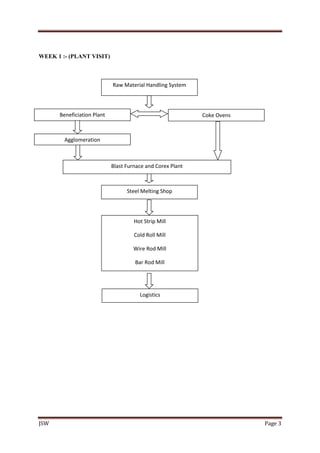
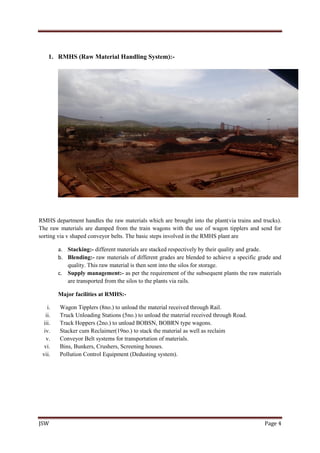
This document provides a summary of a summer internship at JSW Steel Limited in Ballari, Karnataka, India. It was conducted by 6 interns over 4 weeks. The first week involved visiting different departments to understand steel production processes. The remaining 3 weeks focused on the Raw Material Handling Systems department, specifically studying the time motion of wagon tipplers. The document describes the company background, individual plant processes visited in the first week, and objectives and key performance metrics of the Raw Material Handling Systems department where the project was conducted.

![JSW Page 25
Tarpaulin covering: Raw material heaps in yard are covered with tarpaulin cover to protect
from rain and also avoid dust carry away with wind.
Wind-Screen: Wind Screens are installed in RMHS 1 & Energy yards to reduce velocity of
wind into yards so that emission can be avoided.
Air compressors: Air compressors are installed for supplying air at high pressure to fulfil the
De-dusting system requirement also to create water spray/ mist. Water is supplied through
high pressure pumps in Water pump house.
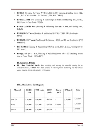
DESCRIPTION OF WAGONS
Most wagons are made of steel, except for a few special-purpose wagons. Some specialized wagons
have been made with stainless steel or special steel alloys to reduce corrosion. Some Recently [12/04]
with the rising price of steel IR has been looking into using steel substitutes, and plans have also been
drawn up for the production of aluminium-body wagons (see BOBNAL, BOBRAL below). It is
thought that about 750 aluminium wagons will be built in 2005-2006. Interestingly, some of these are
said to be of a 4-wheel design. The tare weight is expected to be reduced by about 4.2 tonnes. A few
aluminium wagons are already in use on a trial basis. Aluminium wagons besides being of a lower
cost and having a lower tare weight, also have the advantage of suffering less corrosion in many
circumstances. A typical rake with aluminium wagons instead of steel ones would carry almost 240t
more goods.
As seen in the permanent way section, many BG routes have rails that allow axle loads of up to 25t, or
in many cases 22.5t. However, normal operating procedures on IR restrict BG wagons to 20.3t of axle
load. Now [3/05] it has been proposed that this be raised to 23t.
Descriptions of some wagon types follow below:
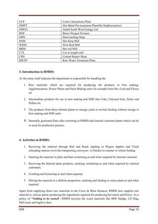
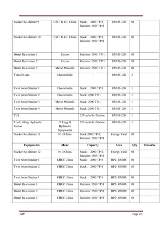
BOX High-sided bogie open wagon. Side discharge arrangement. 55 ton capacity, 25 ton tare. Used
for coal and other bulk goods. About 7,000 of these are in use [2006]; this class is in decline since the
advent of the BOXN and other variants. There used to be over 14,000 of these in the 1990s, and about
8,800 as late as 2005. BOXT, BOXR, and BOXC are the same with transition, screw, and CBC
couplers, respectively.](https://image.slidesharecdn.com/ce769e21-7558-435a-8965-435fc7f0a60b-161019151313/85/Jindal-report-26-320.jpg)
![JSW Page 26
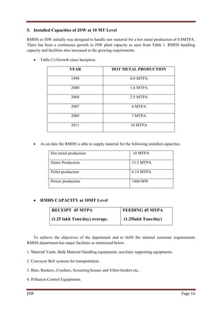
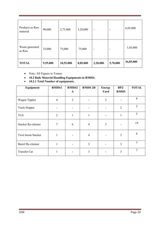
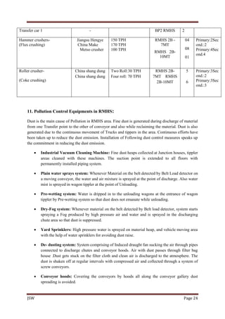
BOXNBOX variant:
High-sided bogie open wagon with pneumatic brakes, high tensile CBC couplers, CASNUB cast
steel bogies, cartridge tapered roller bearings. Perhaps the most common wagon, there are around
64,000 or more of these in use [2002-2006]. Used for bulk movement of material commodities (coal,
iron ore, stone, etc.).
Max. axle load 20.32t
Spring grouping per bogie - outer 12
Spring grouping per bogie - inner 8
Tare 22.47t
Payload (RDSO spec.) 58.81t
Payload (revised, incl. tolerance) 64+2 = 66t (RC 13/2007)
Gross load (RDSO spec., excl. tolerance) 81.28t
Gross load (revised, incl. tolerance) 86.47+2 = 88.47t
Capacity 56.3m3
Width 3.2m
Height 3.225m
Length over headstock 9.784m
Length over coupler faces 10.71m
Distance between bogie centres 524m
Standard rake size (2007) 59
Total train load (incl. BVZC, RDSO spec.,
excl. tolerance) 4809.3t
Total train load (incl. BVZC, CC+8+2) 5399.32 (BOXNM1) A.L. - 22.9 tt
Total train load (incl. BVZC, revised, incl. tolerance) 5233.53t
RDSO design speed (loaded) 60 (CC+8+2), 75 (CC)
RDSO design speed (empty) 80 (CC+8+2), 80 (CC)
CRS sanctioned speed (loaded, SER) 60km/h (CC+8+2), 75km/h (CC)
CRS sanctioned speed (empty, SER) 80km/h (CC+8+2), 80km/h (CC)](https://image.slidesharecdn.com/ce769e21-7558-435a-8965-435fc7f0a60b-161019151313/85/Jindal-report-27-320.jpg)


![BSP Project (Based on Continuous Casting) [Final]](https://cdn.slidesharecdn.com/ss_thumbnails/1cb7ea7d-f281-4d52-a9fa-9483a29f6fbc-150714213851-lva1-app6892-thumbnail.jpg?width=640&height=640&fit=bounds)