
Download as PDF, PPTX

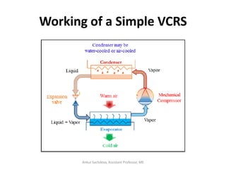


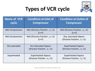
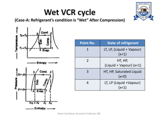
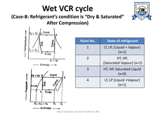
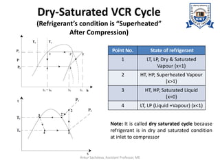
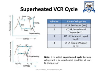
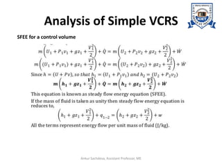

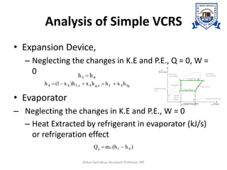


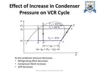
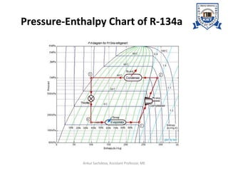

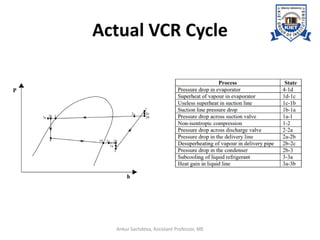
The document provides an introduction to vapor compression refrigeration systems (VCRS), explaining their operational principles, components, and cycles involved in refrigeration. It outlines the processes of isentropic compression, heat rejection, and extraction that occur in VCRS, as well as the characteristics of different vapor compression cycles based on the refrigerant's condition. Additionally, the document discusses methods to improve performance and the effects of pressure changes on the VCR cycle.


