SlideShare a Scribd company logo
1 of 58
1/11/2023 1
CLUTCH
Principle of operation of clutches
• Clutch works on the principle of friction. When two friction surfaces are
brought in contact with each other and pressed with certain force they are
united due to friction between them.
If one is rotated, other will also rotate during this condition. It can be
separated or brought into contact whenever required.
One surface is referred as driving member and other as driven member.
The friction between two surfaces depends upon
• Area of contact surface.
• Force applied on them.
• Coefficient of friction of surface of material.
When the driven member is brought in contact with driver, the clutch slips
initially. As the pressure increases the driven member is brought to the
speed of the driving member. When the speed of both members becomes
equal then two members are in frictional contact without any slip and
clutch is said to be fully engaged. The driving torque can be increased by
increasing the effective radius of contact, coefficient of friction, clamping
force, or the number of contact surfaces.
Clutch components
• Driving member
– Uses a pressure plate assembly and the flywheel, which
are bolted together such that the assembly rotates at
the speed of the engine. The pressure plate requires
about 7850 kPa pressure to hold the clutch.
• Driven Member
– The driven member consists of a disc or plate assembly
and the clutch shaft. The driven plate assembly is held
between the flywheel and the pressure plate assembly
under the action of pressure springs
• Operating member
– It consists of release bearing, release lever, foot pedal,
linkage and the spring with adjuster.
1/11/2023 3
1/11/2023 4
FUNCTIONS
 To engage and disengage the transmission from engine to
the remaining parts of transmission. (To allow the engine to
be separated from rest of the transmission system)
 (a) Starting and running the engine at a sufficiently high
speed to generate sufficient power necessary for moving
the vehicle from rest.
 (b) Smooth shifting of the gears so that damage to gear
teeth can be avoided.
 (c) Stopping the vehicle after applying brakes.
 The second function of the clutch is to allow the engine to
take up the driving load of the vehicle gradually and
without shock.
1/11/2023 5
Requirements of clutch
1. Transmit maximum torque of the engine.
2. Engage gradually to avoid sudden jerks.
3. Able to dissipate large amount of heat generated during
clutch operation.
4. Dynamically balanced, particularly in the case of high
speed engine clutches.
5. To damp vibrations and to eliminate noise produced
during power transmission.
6. As small as possible so that it will occupy minimum
space.
7. Easy to operate requiring as little exertion on the part of
the driver.
8. Light in weight.
9. Trouble free and have longer life.
10. Easy to inspect, adjust and repair.
Desired Features
(a) The force required by a clutch to separate the drive must not be excessive.
(b) The clutch friction surface should maintain a reasonable coefficient of
friction under all operating conditions.
(c) The rubbing surfaces of the clutch must be correctly machined and be hard
enough to resist wear but not so hard to cause scoring.
(d) The rubbing surfaces must provide adequate surface area and mass to
transfer and absorb the heat generated.
(e) It should have provision for adequate cooling or ventilation to dissipate
generated heat. The clutch material should have reasonable thermal
conductivity to dissipate the heat so that distortion of the flywheel and
pressure-plate is avoided.
(g) It should use a friction material, which must withstand high temperatures
and clamping loads without crushing.
1/11/2023 6
1/11/2023 7
POSITIVE ENGAGEMENT CLUTCH GRADUAL ENGAGEMENT CLUTCH
FRICTION
CLUTCH
CONE DISC CENTRIFUGAL SEMI CENTRIFUGAL ELECTRO-MAGNETIC
INT EXT SINGLE MULTI DIAPHRAGM
DRY WET
ONE WAY
CLUTCHES
FLUID
CLUTCH
CLUTCH
1/11/2023 8
SINGLE PLATE DRY CLUTCH
1/11/2023 9
Working / operation:
In fully engaged condition the driven plate is firmly clamped
between the flywheel and pressure plate due to the force
applied by springs. This forms a non-slip connection between
the driving and driven plates.
Hence when the flywheel rotates, the clutch plate also rotates
and this cause the transmission of power to the input shaft of
gear box through splines.
When clutch pedal is depressed the pressure on the driven
plate is released by compressing the pressure springs through
the release fingers. In this condition there is no force acting on
the clutch plate and is free between the flywheel and pressure
plate. This disengaged condition ensures easier shifting of
gears.
1/11/2023 10
CLUTCH OPERATION
1/11/2023 11
Sectional view of a clutch showing the linkages to the clutch pedal
1/11/2023 12
Clutch Disc or Friction Disc. Facings and the drive washer have
been partly cut to show the springs
1/11/2023 13
CLUTCH PLATE
MULTIPLATE CLUTCHES
• The clutch having more than three discs is referred as multi
disc clutch or multi plate clutch.
• It is similar to single plate clutch but has more number of
frictional and metallic plates. Due to the increase in the
numbers of plates (friction) the frictional surface in contact
is also increased which increases the capacity of the clutch
to transmit the same torque as the diameter of the plate
clutch.
• Hence the clutches are mostly commonly in two wheelers
and three wheelers due to compact in size. It is used in
heavy duty transmission system for transmitting higher
torque. (For example torque transmission in heavy earth
moving equipments) and power take off (P. T. O.)
transmission in tractors.
1/11/2023 15
MULTIPLATE CLUTCH
• Multi plate clutch can be dry type or wet type. The wet type
clutch is partially filled with oil. The coefficient of friction in
oil varies from 0.07 to 0.17 on asbestos based fabrics.
• The oil acts as cushioning medium to provide smooth
engagement and disengagement
• The oil also carries the heat dissipated by the clutch due to
friction. This reduces operations temperature and increases
the life of the clutch plates.
• The oil acts as lubricant and reduces axial thrust lost due to
bending on splines.
• The major disadvantage is the reduction in coefficient of
friction when immersed in oil. It can be compensated by
using high operating pressure of different friction material.
Generally cork inserted multi plate clutches are used in wet
clutches. In wet clutches the fluid under pressure is fed
along the shaft.
1/11/2023 16
MULTIPLATE CLUTCHES
1/11/2023 17
MULTIPLATE CLUTCH
MULTIPLATE CLUTCHES
• Construction: Construction of multi plate clutches is similar
to single plate clutch except the arrangement of number of
friction plates and metal plates.
• It consists of inner drum which is referred to clutch shaft
and has a number of plates splined to the outer surface.
• Another drum is coupled to fly wheel and carries a number
of plates splined to its inner surface. The plates are
arranged in alternate manners. The plates can revolve with
the drum as well as it can slide axially.
• A spring keeps the outer and inner plates pressed together,
so that the driving members transmit the power to the
driven member.
• The clutches can be disengaged by pulling the inner drum
against the spring force.
DIAPHRAGM CLUTCHES
• In this type of diagram type springs are used instead of coil /
helical springs.
• This type of clutch does not require any release levers as the
spring itself acts as the series of levers.
• This type of springs do not have constant rate characteristics
as in the case of coil springs and the pressure on the
diaphragm springs increases until it is in flat position,
thereafter decreases after passing this position.
• Hence the driver does not have to exert heavy pedal pressure
to hold the clutch out of engagement compared to coil spring
type.
• In coil spring type the spring pressure increases when the
pedal is depressed to disengage the clutch and high pressure
is required to keep the clutch in disengaged position.
1/11/2023 20
DIAPHRAGM CLUTCHES
1/11/2023 21
Disassembled diaphragm spring clutch
1/11/2023 22
• Working:
• In the engaged position the spring pivots on the inner pivot rings
as it is held on the clutch cover so that its outer rings contacts
with the pressure plate. Again in this conical position the spring
exerts through pressure to keep the pressure plate in firm contact
with the clutch plate and flywheel.
• When the pedal is depressed the linkage moves release bearing
toward the flywheel. When the pedal is depressed the linkage
moves release bearing towards the flywheel to disengage the
clutch.
• As the bearing contacts with inner position of the conical springs it
moves that position forward which cause the link to move
backward. This removes the pressure on the pressure plate and
release the clutch plate from contact with other driving members.
• Another type of conical spring used is the crown spring. This type
differs from the tapered finger type with its surface corrugated
instead of flat and the centre section is continuous without any
spring. The clutch spring fits between the pressure plate and
clutch cover. The entire assembly is held together by six spring
retainer located on the pressure plate. The actuation of this type
of spring is similar to integral / split type diaphragm spring.
1/11/2023 23
CLUTCH ENGAGED
1/11/2023 24
CLUTCH DISENGAGED
1/11/2023 25
Double disc
diaphragm clutch
1/11/2023 26
DIAPHRAGM CLUTCHES
CONE CLUTCHES
• They are wedge clutch provides a positive drive when the external face of
the male cone member engages with the internet face of recessed conical
member.
• The facing is usually fitted to the female or recessed member in order to
improve heat dissipation and durability.
• Normally cone clutch are used with epicyclic gear trains for a higher
torque transmission. The energy which a cone clutch can absorb during on
engagement is less compared to the energy absorbed by a multiple clutch.
• But it is compact, cheaper and requires low clamping load due to the
wedging action. The cone clutches are loaded by spring or hydraulic
cylinders.
• Wedge angle and accurate axial alignment are the two important factors
for good cone clutch performance. If the wedge angle is very less, it
results in excessive wedge action and fierce engagement.
• This in turn results in difficult operation for disengagement. If the wedge
angle is too large it reduces torque transmission capacity of the clutch and
make the clutches to skid.
• Semi-cone angle of 12-16 are commonly used for effective torque
transmission.
• The torque transmitted by a cone clutch is given by
T = μW (r1 + r2) / 2 sin α
Where, r1 and r2 are the radius of large and small cone (friction) in
meters. α is the semi cone angle
1/11/2023 28
CONE CLUTCH
During the engagement of clutch the driven member is forced towards the driving
cone by the spring force. Hence the power is transmitted from the engine to the
driving cone, driving cone to driven cone and driven to the gear box. When the
clutch is to be disengaged the driven cone is to be pulled off by means of actuates
cenkages and contact surfaces are separated hence no power is transmitted to the
clutch shaft.
SEMICENTRIFUGAL CLUTCH
• This type of clutch makes use of centrifugal force
to assist the spring force at high speed.
• To reduce the effort of the driver operates the
clutch the assistance is taken by the centrifugal
force.
• To transmit small torque, spring with minimum
stiffness is used which is sufficient for applying
the required amount of force and also not so stiff
to minimize the strain of the driver during
disengagement.
• When high power is transmitted through the
clutch then pressure of the springs is a
considerable factor.
1/11/2023 30
SEMICENTRIFUGAL CLUTCH
• In semi-centrifugal clutches help is taken by centrifugal
force by keeping certain weights in eccentric position.
• The springs are designed to transmit the power at normal
speeds and at high speed the assistance is taken by the
weights, the weighted lever is hanged at three points at
regular intervals.
• The lever is provided with fulcrum connected to the clutch
cover at one end hinged to the pressure plate ate centre
and the weight is connected at the outer end.
• The tail of the lever is provided with the adjusting screw by
means of which centrifugal force on the pressure plate can
be adjusted.
• During the increase in speed the weight moves about
fulcrum due to the centrifugal force of the weight and hence
the pressure plate moves towards the flywheel increasing
the torque transmitting capacity.
CENTRIFUGAL CLUTCH
• This type of clutches operates automatically
depending on engine speed of elements.
• The use of clutch pedal, pressure spring and also
clutch making the operation very simple of
makes use of centrifugal force to apply the force
on the floating plate as well as on the pressure
plate for keeping the clutch in engaged position.
• In this type, transmission of the power is
controlled by the operation of the accelerator.
• It makes the driving operation very easy and
convenient.
• Hence it is used in automatic transmission in two
wheelers with variator mechanisms or two-
wheeler without gear mechanism.
1/11/2023 33
CENTRIFUGAL CLUTCH
CENTRIFUGAL CLUTCH
• This system consists of flywheel as driving member and pressure
plate as the driven member. The pressure plate is provided with
friction lining on its outer surface.
• The pressure plate is actuated by means of floating spring which
exerts pressure on the floating. The spring on the fly wheel keeps
the clutch is disengaged position at low speeds.
• When the speed increases the weight flees off thereby operating
bell crank lever and pressing the floating plate. The force acting
on the floating plate is transmitted to the pressure plate through
the helical spring placed between floating plate and pressure
plated.
• Due to this force the pressure plate is pressed on to flywheel
providing the transmission through the friction lining and thereby
resulting in engagement of clutch.
• The stop provided above the weight limits the amount of
centrifugal force of the speed is increased over this limit the
pressure on plate will be constant.
CENTRIFUGAL CLUTCH
• Other type of centrifugal clutches are used in automobiles
(generally in mopeds) consists of spider as the driving member.
• The spider has four shoes having the frictional surfaces. These are
kept in contact with the cylindrical clutch case by means of
springs.
• As the speed increases, the shoes extend outwards due to
centrifugal force and make contact with the cylindrical clutch to
transmit the power.
• The transmission starts as soon as the spring force exceeds the
spring force and shoes extends outwards.
• Hence the power transmission starts as soon as the engine starts
rotating at a speed enough to develop the required centrifugal
force.
• The transmission stops as soon as the engine speed drops below
the desired value. Hence no power is transmitted to the road
wheels when the engine is idle or running at lesser speed than the
desired value.
1/11/2023 36
CENTRIFUGAL CLUTCH
1/11/2023 37
ELECTROMAGNETIC CLUTCH
1/11/2023 38
ELECTROMAGNETIC CLUTCH
• In this system the clutch is controlled by means electric
current supplied to the field windings in the flywheel. The
fly wheel is attached with the field winding, which is given
electric current by means of battery, dynamo or alternator.
The construction feature of main components is almost
similar to the single plate clutch.
• When electric current is supplied to the windings the
flywheel will attract the pressure plate and clutch plate is
forced between pressure plate and flywheel resulting in
engagement.
• When the supply to the winding is cut off the clutch is
disengaged by releasing the pressure plate due to the force
exerted by the helical springs or tension springs.
• Electromagnetic clutch consists of a clutch release switch.
When then driver holds the gear lever to change the gear,
the switch is operated cutting off the current to the winding
which causes the clutch disengaged.
ELECTROMAGNETIC CLUTCH
• When the vehicle is stalling, the engine speed is lower & the
dynamo output is low, the clutch is not firmly engaged.
• Therefore, three springs are also provided on the pressure plate
which helps the clutch engaged firmly at low speed also
• The forces of the electromagnet can be regulated by means of an
electrical resistance provided with acceleration system and
controlled by the accelerator pedal.
• When the speed is increased, the accelerator pedal is pressed and
the resistance is gradually cut off and thus in this way, force of
electromagnet is increased and clutch transmission becomes more
rigid.
1/11/2023 40
Positive Engagement
Clutches
Sliding dog Clutch/Dog and Splines Clutch
• This type of clutch is used to lock two shafts together or to lock a gear to
a shaft.
• It consists of a sleeve having two sets of internal splines. It slides on a
splined shaft with smaller diameter splines.
• The bigger diameter splines match with the external dog clutch teeth on
driving shaft. When the sleeve is made to slide on the splined shaft, its
teeth match with the dog clutch teeth of the driving shaft.
• Thus the sleeve turns the splined shaft with the driving shaft. The clutch is
said to be engaged. To disengage the clutch, the sleeve is moved back on
the splined shaft to have no contact with the driving shaft.
• This type of clutch has no tendency to sup. The driven shaft revolves
exactly at the same speed as that of the driving shaft, as soon as the
clutch is engaged. Therefore it is also known as positive engagement
clutch.
1/11/2023 42
One way/ Overrunning
Clutches
These types of clutches are used to transmit the power in only one direction. The power is
transmitted from the driver to driven and not vice-versa. When the drive rotates in the reverse
direction the clutches slips or disengages. This type of clutch mainly consists of an inner race and
outer race. The inner race is connected to the driver and the outer race is connected to the driven.
SPRAG CLUTCH:
• In this type several sprags are equally spaced between the inner
and outer races. The sprags can be installed in the direction as
shown in the figure or can be tuned through 1800 to provide anti-
clockwise rotation. Generally sprags are provided with energizing
springs to hold the individual sprags against the two races.
• When the inner race rotates in anticlockwise direction the sprag
tilts in the same direction of rotation.
• Due to this action the sprag wedges between the inner and outer
race. As a result the outer race rotates in the same direction as
that of inner race and at the same speed.
• If the outer race rotates at more speed then the wedging action is
removed and no power is transmitted. Similar action occurs if the
inner race tries to rotate in the opposite direction.
• One way clutches are used to transmit the power in clockwise or
anticlockwise direction by the proper positioning of springs.
BALL AND ROLLER CLUTCH
• In this the inner race and outer races has several ramp like
grooves in which the clutch elements (roller or balls) are placed.
• A spring is positioned in front of these elements. Its purpose is to
hold the element against the ramp and race surfaces.
• When the inner racer is rotated in clockwise direction, the friction
between the inner race and rollers or balls moves them slightly in
the same direction.
• This wedges the balls or rollers between the ramps and surface of
the inner race or outer race, causing the outer race to be driven in
the same speed as that of the inner race.
• If the outer race is rotated faster than the inner race, distance
between the ramp and race increases, removing the wedging
action of the clutch element and no power is transmitted between
the inner and outer race.
• If the inner race is rotated in the opposite direction it will result in
the similar way where no power is transmitted between the
driving and driven member.
1/11/2023 45
The Clutch Cable has a self adjusting device that maintains the
proper free travel of the clutch pedal
Self Adjusting Clutch.
1/11/2023 46
Hydraulically operated clutch
1/11/2023 47
The clutch operated by a cable from the clutch pedal
Cable operated Clutch
1/11/2023 48
Clutch Operating Mechanism
Mechanically Operated Clutch
A cross shaft type withdrawal mechanism is as shown in figure
Clutch operating mechanisms
Mechanically Operated Clutch
• To put and hold the clutch in the disengaged position the
clutch withdrawal mechanism is necessary. This mechanism
including foot pedal and clutch actuating levers etc. are also
seen some times from outside also.
• When the foot pedal is pressed by the driver the shaft
having the two projections and supported at two bearings is
turned, thereby moving the housing with the pressures of
the pins. In this way this motion of the housing disengages
the clutch.
• When the manual pressure from the foot pedal is removed,
the housing comes in its original position thereby the clutch
again engaged.
1/11/2023 50
Vacuum Operated Clutch
Clutch Operating Mechanism
VACUUM CLUTCH
• The vacuum clutch is operated by the vacuum existing in the engine
manifold.
• Fig shows the mechanism of a vacuum clutch. It consists of a vacuum
cylinder with piston, solenoid operated valve, reservoir and a non-return
valve.
• The reservoir is connected to the engine manifold through a non return
valve.
• Vacuum cylinder is connected to the reservoir through solenoid operated
valve.
• The solenoid is operated from the battery and the circuit incorporates a
switch which is placed in the gear lever.
• The switch is operated when the driver holds the lever to change gears.
VACUUM CLUTCH
• When the throttle is wide opened, the pressure in the inlet manifold
decreases due to which the non-return valve closes, isolating the reservoir
from the manifold. Thus a vacuum exists in the reservoir all the time.
• In the normal operation, the switch in the gear lever remains off, the
solenoid operated valve remains in its bottom position. In this positions the
atmospheric pressure acts on both the side of the vacuum cylinder, because
the vacuum cylinder is open, so also atmosphere though a vent.
• When the driver holds the lever to change the gear, the switch is closed;
energizing the solenoid which pulls the valve up. This connects one side of
vacuum cylinder to the reservoir.
• Due to the difference of pressure on the vacuum cylinder piston, it moves.
This movement of the piston is transmitted by a linkage to the clutch,
causing it to disengage.
• When the driver is not operating the gear lever, the switch is open and the
clutch remains engaged due to the force of springs.
1/11/2023 53
Hydraulic Operated Clutch
Clutch Operating Mechanism
Hydraulic Operated Clutch
• The hydraulic clutch is operated in the same way as the vacuum
clutch. Only the difference is that it is operated by oil pressure
whereas the vacuum clutch is operated by vacuum.
• Fig. shows the mechanism of a hydraulic clutch. It consists of a
cylinder with piston, control valve, pump, accumulator and oil
reservoir. The piston is connected to the clutch by a linkage. The
pump is operated by the engine itself.
• The oil from the reservoir is pumped into the accumulator tank.
The accumulator tank is connected to the cylinder through the
control valve. The control valve is electrically controlled by a
switch in the gear lever.
Hydraulic Operated Clutch
• When the driver holds the gear lever to change the gears,
the switch is operated to open the control valve admitting
the oil under pressure to the cylinder.
• Due to the oil pressure, the piston moves causing the clutch
to be disengaged.
• As soon as the driver leaves the gear lever, the switch is
open which closes the control valve and the clutch is
engaged.
1/11/2023 56
FRICTION MATERIALS
(i) Mill board type: This material is in the form of sheets made of asbestos and
treated with certain impregnates.
(ii) Moulded type: When asbestos fibers are mixed with a suitable binder and
heated to a definite temperature and then moulded in dies under pressure, this
type of friction material is called “moulded type”. To improve the wearing
qualities of the material (sometimes metallic wires are also inserted). This type
of lining is stronger, dense and capable to transmit heavy loads through it. The
disadvantage is only this that moulding for each size lining is very costly.
(iii) Woven type: This type of material is made by spinning threads from asbestos
fibres, weaving this thread into a cloth and then impregnating it with a bonding
material. This type of material is further divided into classes;
(a) the solid woven variety is woven to the required thickness in one operation
and has a greater mechanical strength;
(b) the laminated variety consists of layers of cloth placed on top of
each other and held together by the bonding material. Both types
may incorporate brass wire.
1/11/2023 57
CLUTCH LINING MATERIALS
Common materials used for clutch lining are:
(i) Asbestos: It can be used at high temperature also and
linings of this material have coefficient of friction of about
0.2
(ii) Reybestos and Ferodo: These materials are most suitable
and generally used for clutch friction linings and have a co
efficient of friction of about 0.35.
(iii) Leather: The co-efficient of friction between dry leather
and iron is 0.27.
(iv) Cork: The co-efficient of friction between cork and steel or
iron is 0.32.
(v) Fabric: This material has co-efficient of friction about 0.4,
but it cannot be used at high temperature.
1/11/2023 58
Any Questions?

More Related Content

What's hot (20)

Synchromesh gear box
Synchromesh gear boxSynchromesh gear box
Synchromesh gear box
 
Steering System
Steering SystemSteering System
Steering System
 
Brakes
BrakesBrakes
Brakes
 
Differentail
Differentail Differentail
Differentail
 
Differential in automobile
Differential in automobileDifferential in automobile
Differential in automobile
 
Clutch
ClutchClutch
Clutch
 
Single plate clutch presentation
Single plate clutch presentationSingle plate clutch presentation
Single plate clutch presentation
 
Clutch
ClutchClutch
Clutch
 
Clutches ( Single Plate and Multi Plate)
Clutches ( Single Plate and Multi Plate) Clutches ( Single Plate and Multi Plate)
Clutches ( Single Plate and Multi Plate)
 
Propeller shaft
Propeller shaftPropeller shaft
Propeller shaft
 
CLUTCHES
CLUTCHESCLUTCHES
CLUTCHES
 
Manual Transmission in Automotive
Manual Transmission in AutomotiveManual Transmission in Automotive
Manual Transmission in Automotive
 
Friction in Clutch
Friction in ClutchFriction in Clutch
Friction in Clutch
 
slides on clutches
slides on clutchesslides on clutches
slides on clutches
 
Clutch System
Clutch System Clutch System
Clutch System
 
Operation of centrifugal clutch
Operation of centrifugal clutchOperation of centrifugal clutch
Operation of centrifugal clutch
 
Clutches
ClutchesClutches
Clutches
 
5 classification of brakes
5 classification of brakes5 classification of brakes
5 classification of brakes
 
Sliding mesh gear box
Sliding mesh gear boxSliding mesh gear box
Sliding mesh gear box
 
BASICS OF TRANSMISSION SYSTEM
BASICS OF TRANSMISSION SYSTEMBASICS OF TRANSMISSION SYSTEM
BASICS OF TRANSMISSION SYSTEM
 

Similar to CLUTCH

Transmission Systems - Clutch
Transmission Systems - ClutchTransmission Systems - Clutch
Transmission Systems - ClutchNirmal S
 
automotive transmission system clutch and system
automotive transmission system clutch and systemautomotive transmission system clutch and system
automotive transmission system clutch and systemTHESRIF
 
Automobile Clutch Functions & Types.ppt
Automobile  Clutch Functions & Types.pptAutomobile  Clutch Functions & Types.ppt
Automobile Clutch Functions & Types.pptAshishDahiya36
 
Unit-3-Transmission system of Automobile
Unit-3-Transmission system of Automobile Unit-3-Transmission system of Automobile
Unit-3-Transmission system of Automobile Dr.S.SURESH
 
UNIT-III-TRANSMISSION SYSTEMS REAR AXLES
UNIT-III-TRANSMISSION SYSTEMS REAR AXLESUNIT-III-TRANSMISSION SYSTEMS REAR AXLES
UNIT-III-TRANSMISSION SYSTEMS REAR AXLESDineshKumar4165
 
UNIT-III-TRANSMISSION SYSTEMS.pptx
UNIT-III-TRANSMISSION SYSTEMS.pptxUNIT-III-TRANSMISSION SYSTEMS.pptx
UNIT-III-TRANSMISSION SYSTEMS.pptxShanmathyAR2
 
UNIT-III-TRANSMISSION SYSTEMS.pptx
UNIT-III-TRANSMISSION SYSTEMS.pptxUNIT-III-TRANSMISSION SYSTEMS.pptx
UNIT-III-TRANSMISSION SYSTEMS.pptxprakash0712
 
CLUTCHES AND THERE PARTS OF CLUTCHES PLATES PPT.pptx
CLUTCHES AND THERE PARTS OF CLUTCHES PLATES PPT.pptxCLUTCHES AND THERE PARTS OF CLUTCHES PLATES PPT.pptx
CLUTCHES AND THERE PARTS OF CLUTCHES PLATES PPT.pptxRushabhNagpure1
 
Clutches for automobile
Clutches for automobile Clutches for automobile
Clutches for automobile sgrsoni45
 
Transmission system_clutch
Transmission system_clutchTransmission system_clutch
Transmission system_clutchDevendra Yadav
 

Similar to CLUTCH (20)

Transmission Systems - Clutch
Transmission Systems - ClutchTransmission Systems - Clutch
Transmission Systems - Clutch
 
automotive transmission system clutch and system
automotive transmission system clutch and systemautomotive transmission system clutch and system
automotive transmission system clutch and system
 
Automobile Clutch Functions & Types.ppt
Automobile  Clutch Functions & Types.pptAutomobile  Clutch Functions & Types.ppt
Automobile Clutch Functions & Types.ppt
 
Unit-3-Transmission system of Automobile
Unit-3-Transmission system of Automobile Unit-3-Transmission system of Automobile
Unit-3-Transmission system of Automobile
 
UNIT-III-TRANSMISSION SYSTEMS REAR AXLES
UNIT-III-TRANSMISSION SYSTEMS REAR AXLESUNIT-III-TRANSMISSION SYSTEMS REAR AXLES
UNIT-III-TRANSMISSION SYSTEMS REAR AXLES
 
UNIT-III-TRANSMISSION SYSTEMS.pptx
UNIT-III-TRANSMISSION SYSTEMS.pptxUNIT-III-TRANSMISSION SYSTEMS.pptx
UNIT-III-TRANSMISSION SYSTEMS.pptx
 
UNIT-III-TRANSMISSION SYSTEMS.pptx
UNIT-III-TRANSMISSION SYSTEMS.pptxUNIT-III-TRANSMISSION SYSTEMS.pptx
UNIT-III-TRANSMISSION SYSTEMS.pptx
 
Disc Clutch
Disc ClutchDisc Clutch
Disc Clutch
 
CLUTCHES AND THERE PARTS OF CLUTCHES PLATES PPT.pptx
CLUTCHES AND THERE PARTS OF CLUTCHES PLATES PPT.pptxCLUTCHES AND THERE PARTS OF CLUTCHES PLATES PPT.pptx
CLUTCHES AND THERE PARTS OF CLUTCHES PLATES PPT.pptx
 
Transmission system
Transmission systemTransmission system
Transmission system
 
Clutches for automobile
Clutches for automobile Clutches for automobile
Clutches for automobile
 
CLUTCHES.pptx
CLUTCHES.pptxCLUTCHES.pptx
CLUTCHES.pptx
 
Clutch1.ppt
Clutch1.pptClutch1.ppt
Clutch1.ppt
 
clutches.pptx
clutches.pptxclutches.pptx
clutches.pptx
 
clutches.pptx
clutches.pptxclutches.pptx
clutches.pptx
 
clutches.pptx
clutches.pptxclutches.pptx
clutches.pptx
 
Transmission system_clutch
Transmission system_clutchTransmission system_clutch
Transmission system_clutch
 
clutch.ppt
clutch.pptclutch.ppt
clutch.ppt
 
clutch.ppt
clutch.pptclutch.ppt
clutch.ppt
 
clutch.ppt
clutch.pptclutch.ppt
clutch.ppt
 

More from RINUSATHYAN

Frameworks provide structure. The core objective of the Big Data Framework is...
Frameworks provide structure. The core objective of the Big Data Framework is...Frameworks provide structure. The core objective of the Big Data Framework is...
Frameworks provide structure. The core objective of the Big Data Framework is...RINUSATHYAN
 
Data analytics for engineers- introduction
Data analytics for engineers-  introductionData analytics for engineers-  introduction
Data analytics for engineers- introductionRINUSATHYAN
 
Neural-Networks.ppt
Neural-Networks.pptNeural-Networks.ppt
Neural-Networks.pptRINUSATHYAN
 
artificial-neural-networks-rev.ppt
artificial-neural-networks-rev.pptartificial-neural-networks-rev.ppt
artificial-neural-networks-rev.pptRINUSATHYAN
 
Sampling Distributions
Sampling DistributionsSampling Distributions
Sampling DistributionsRINUSATHYAN
 

More from RINUSATHYAN (14)

Frameworks provide structure. The core objective of the Big Data Framework is...
Frameworks provide structure. The core objective of the Big Data Framework is...Frameworks provide structure. The core objective of the Big Data Framework is...
Frameworks provide structure. The core objective of the Big Data Framework is...
 
Data analytics for engineers- introduction
Data analytics for engineers-  introductionData analytics for engineers-  introduction
Data analytics for engineers- introduction
 
apriori.pdf
apriori.pdfapriori.pdf
apriori.pdf
 
Neural-Networks.ppt
Neural-Networks.pptNeural-Networks.ppt
Neural-Networks.ppt
 
artificial-neural-networks-rev.ppt
artificial-neural-networks-rev.pptartificial-neural-networks-rev.ppt
artificial-neural-networks-rev.ppt
 
forecasting
forecastingforecasting
forecasting
 
regression
regressionregression
regression
 
Sampling Distributions
Sampling DistributionsSampling Distributions
Sampling Distributions
 
Decision tree
Decision treeDecision tree
Decision tree
 
disc brake
disc brakedisc brake
disc brake
 
rpt.pdf
rpt.pdfrpt.pdf
rpt.pdf
 
RPT- ppt.pdf
RPT- ppt.pdfRPT- ppt.pdf
RPT- ppt.pdf
 
FMS.pdf
FMS.pdfFMS.pdf
FMS.pdf
 
ERP ppt.ppt
ERP ppt.pptERP ppt.ppt
ERP ppt.ppt
 

Recently uploaded

What are the advantages and disadvantages of membrane structures.pptx
What are the advantages and disadvantages of membrane structures.pptxWhat are the advantages and disadvantages of membrane structures.pptx
What are the advantages and disadvantages of membrane structures.pptxwendy cai
 
Introduction to Multiple Access Protocol.pptx
Introduction to Multiple Access Protocol.pptxIntroduction to Multiple Access Protocol.pptx
Introduction to Multiple Access Protocol.pptxupamatechverse
 
(RIA) Call Girls Bhosari ( 7001035870 ) HI-Fi Pune Escorts Service
(RIA) Call Girls Bhosari ( 7001035870 ) HI-Fi Pune Escorts Service(RIA) Call Girls Bhosari ( 7001035870 ) HI-Fi Pune Escorts Service
(RIA) Call Girls Bhosari ( 7001035870 ) HI-Fi Pune Escorts Serviceranjana rawat
 
Microscopic Analysis of Ceramic Materials.pptx
Microscopic Analysis of Ceramic Materials.pptxMicroscopic Analysis of Ceramic Materials.pptx
Microscopic Analysis of Ceramic Materials.pptxpurnimasatapathy1234
 
Study on Air-Water & Water-Water Heat Exchange in a Finned Tube Exchanger
Study on Air-Water & Water-Water Heat Exchange in a Finned Tube ExchangerStudy on Air-Water & Water-Water Heat Exchange in a Finned Tube Exchanger
Study on Air-Water & Water-Water Heat Exchange in a Finned Tube ExchangerAnamika Sarkar
 
Structural Analysis and Design of Foundations: A Comprehensive Handbook for S...
Structural Analysis and Design of Foundations: A Comprehensive Handbook for S...Structural Analysis and Design of Foundations: A Comprehensive Handbook for S...
Structural Analysis and Design of Foundations: A Comprehensive Handbook for S...Dr.Costas Sachpazis
 
Analog to Digital and Digital to Analog Converter
Analog to Digital and Digital to Analog ConverterAnalog to Digital and Digital to Analog Converter
Analog to Digital and Digital to Analog ConverterAbhinavSharma374939
 
Porous Ceramics seminar and technical writing
Porous Ceramics seminar and technical writingPorous Ceramics seminar and technical writing
Porous Ceramics seminar and technical writingrakeshbaidya232001
 
(PRIYA) Rajgurunagar Call Girls Just Call 7001035870 [ Cash on Delivery ] Pun...
(PRIYA) Rajgurunagar Call Girls Just Call 7001035870 [ Cash on Delivery ] Pun...(PRIYA) Rajgurunagar Call Girls Just Call 7001035870 [ Cash on Delivery ] Pun...
(PRIYA) Rajgurunagar Call Girls Just Call 7001035870 [ Cash on Delivery ] Pun...ranjana rawat
 
247267395-1-Symmetric-and-distributed-shared-memory-architectures-ppt (1).ppt
247267395-1-Symmetric-and-distributed-shared-memory-architectures-ppt (1).ppt247267395-1-Symmetric-and-distributed-shared-memory-architectures-ppt (1).ppt
247267395-1-Symmetric-and-distributed-shared-memory-architectures-ppt (1).pptssuser5c9d4b1
 
Model Call Girl in Narela Delhi reach out to us at 🔝8264348440🔝
Model Call Girl in Narela Delhi reach out to us at 🔝8264348440🔝Model Call Girl in Narela Delhi reach out to us at 🔝8264348440🔝
Model Call Girl in Narela Delhi reach out to us at 🔝8264348440🔝soniya singh
 
Architect Hassan Khalil Portfolio for 2024
Architect Hassan Khalil Portfolio for 2024Architect Hassan Khalil Portfolio for 2024
Architect Hassan Khalil Portfolio for 2024hassan khalil
 
IMPLICATIONS OF THE ABOVE HOLISTIC UNDERSTANDING OF HARMONY ON PROFESSIONAL E...
IMPLICATIONS OF THE ABOVE HOLISTIC UNDERSTANDING OF HARMONY ON PROFESSIONAL E...IMPLICATIONS OF THE ABOVE HOLISTIC UNDERSTANDING OF HARMONY ON PROFESSIONAL E...
IMPLICATIONS OF THE ABOVE HOLISTIC UNDERSTANDING OF HARMONY ON PROFESSIONAL E...RajaP95
 
Biology for Computer Engineers Course Handout.pptx
Biology for Computer Engineers Course Handout.pptxBiology for Computer Engineers Course Handout.pptx
Biology for Computer Engineers Course Handout.pptxDeepakSakkari2
 
MANUFACTURING PROCESS-II UNIT-5 NC MACHINE TOOLS
MANUFACTURING PROCESS-II UNIT-5 NC MACHINE TOOLSMANUFACTURING PROCESS-II UNIT-5 NC MACHINE TOOLS
MANUFACTURING PROCESS-II UNIT-5 NC MACHINE TOOLSSIVASHANKAR N
 
MANUFACTURING PROCESS-II UNIT-2 LATHE MACHINE
MANUFACTURING PROCESS-II UNIT-2 LATHE MACHINEMANUFACTURING PROCESS-II UNIT-2 LATHE MACHINE
MANUFACTURING PROCESS-II UNIT-2 LATHE MACHINESIVASHANKAR N
 
Current Transformer Drawing and GTP for MSETCL
Current Transformer Drawing and GTP for MSETCLCurrent Transformer Drawing and GTP for MSETCL
Current Transformer Drawing and GTP for MSETCLDeelipZope
 
Sheet Pile Wall Design and Construction: A Practical Guide for Civil Engineer...
Sheet Pile Wall Design and Construction: A Practical Guide for Civil Engineer...Sheet Pile Wall Design and Construction: A Practical Guide for Civil Engineer...
Sheet Pile Wall Design and Construction: A Practical Guide for Civil Engineer...Dr.Costas Sachpazis
 
SPICE PARK APR2024 ( 6,793 SPICE Models )
SPICE PARK APR2024 ( 6,793 SPICE Models )SPICE PARK APR2024 ( 6,793 SPICE Models )
SPICE PARK APR2024 ( 6,793 SPICE Models )Tsuyoshi Horigome
 

Recently uploaded (20)
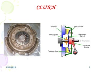
What are the advantages and disadvantages of membrane structures.pptx
What are the advantages and disadvantages of membrane structures.pptxWhat are the advantages and disadvantages of membrane structures.pptx
What are the advantages and disadvantages of membrane structures.pptx
 
Introduction to Multiple Access Protocol.pptx
Introduction to Multiple Access Protocol.pptxIntroduction to Multiple Access Protocol.pptx
Introduction to Multiple Access Protocol.pptx
 
(RIA) Call Girls Bhosari ( 7001035870 ) HI-Fi Pune Escorts Service
(RIA) Call Girls Bhosari ( 7001035870 ) HI-Fi Pune Escorts Service(RIA) Call Girls Bhosari ( 7001035870 ) HI-Fi Pune Escorts Service
(RIA) Call Girls Bhosari ( 7001035870 ) HI-Fi Pune Escorts Service
 
Microscopic Analysis of Ceramic Materials.pptx
Microscopic Analysis of Ceramic Materials.pptxMicroscopic Analysis of Ceramic Materials.pptx
Microscopic Analysis of Ceramic Materials.pptx
 
Exploring_Network_Security_with_JA3_by_Rakesh Seal.pptx
Exploring_Network_Security_with_JA3_by_Rakesh Seal.pptxExploring_Network_Security_with_JA3_by_Rakesh Seal.pptx
Exploring_Network_Security_with_JA3_by_Rakesh Seal.pptx
 
Study on Air-Water & Water-Water Heat Exchange in a Finned Tube Exchanger
Study on Air-Water & Water-Water Heat Exchange in a Finned Tube ExchangerStudy on Air-Water & Water-Water Heat Exchange in a Finned Tube Exchanger
Study on Air-Water & Water-Water Heat Exchange in a Finned Tube Exchanger
 
Structural Analysis and Design of Foundations: A Comprehensive Handbook for S...
Structural Analysis and Design of Foundations: A Comprehensive Handbook for S...Structural Analysis and Design of Foundations: A Comprehensive Handbook for S...
Structural Analysis and Design of Foundations: A Comprehensive Handbook for S...
 
Analog to Digital and Digital to Analog Converter
Analog to Digital and Digital to Analog ConverterAnalog to Digital and Digital to Analog Converter
Analog to Digital and Digital to Analog Converter
 
Porous Ceramics seminar and technical writing
Porous Ceramics seminar and technical writingPorous Ceramics seminar and technical writing
Porous Ceramics seminar and technical writing
 
(PRIYA) Rajgurunagar Call Girls Just Call 7001035870 [ Cash on Delivery ] Pun...
(PRIYA) Rajgurunagar Call Girls Just Call 7001035870 [ Cash on Delivery ] Pun...(PRIYA) Rajgurunagar Call Girls Just Call 7001035870 [ Cash on Delivery ] Pun...
(PRIYA) Rajgurunagar Call Girls Just Call 7001035870 [ Cash on Delivery ] Pun...
 
247267395-1-Symmetric-and-distributed-shared-memory-architectures-ppt (1).ppt
247267395-1-Symmetric-and-distributed-shared-memory-architectures-ppt (1).ppt247267395-1-Symmetric-and-distributed-shared-memory-architectures-ppt (1).ppt
247267395-1-Symmetric-and-distributed-shared-memory-architectures-ppt (1).ppt
 
Model Call Girl in Narela Delhi reach out to us at 🔝8264348440🔝
Model Call Girl in Narela Delhi reach out to us at 🔝8264348440🔝Model Call Girl in Narela Delhi reach out to us at 🔝8264348440🔝
Model Call Girl in Narela Delhi reach out to us at 🔝8264348440🔝
 
Architect Hassan Khalil Portfolio for 2024
Architect Hassan Khalil Portfolio for 2024Architect Hassan Khalil Portfolio for 2024
Architect Hassan Khalil Portfolio for 2024
 
IMPLICATIONS OF THE ABOVE HOLISTIC UNDERSTANDING OF HARMONY ON PROFESSIONAL E...
IMPLICATIONS OF THE ABOVE HOLISTIC UNDERSTANDING OF HARMONY ON PROFESSIONAL E...IMPLICATIONS OF THE ABOVE HOLISTIC UNDERSTANDING OF HARMONY ON PROFESSIONAL E...
IMPLICATIONS OF THE ABOVE HOLISTIC UNDERSTANDING OF HARMONY ON PROFESSIONAL E...
 
Biology for Computer Engineers Course Handout.pptx
Biology for Computer Engineers Course Handout.pptxBiology for Computer Engineers Course Handout.pptx
Biology for Computer Engineers Course Handout.pptx
 
MANUFACTURING PROCESS-II UNIT-5 NC MACHINE TOOLS
MANUFACTURING PROCESS-II UNIT-5 NC MACHINE TOOLSMANUFACTURING PROCESS-II UNIT-5 NC MACHINE TOOLS
MANUFACTURING PROCESS-II UNIT-5 NC MACHINE TOOLS
 
MANUFACTURING PROCESS-II UNIT-2 LATHE MACHINE
MANUFACTURING PROCESS-II UNIT-2 LATHE MACHINEMANUFACTURING PROCESS-II UNIT-2 LATHE MACHINE
MANUFACTURING PROCESS-II UNIT-2 LATHE MACHINE
 
Current Transformer Drawing and GTP for MSETCL
Current Transformer Drawing and GTP for MSETCLCurrent Transformer Drawing and GTP for MSETCL
Current Transformer Drawing and GTP for MSETCL
 
Sheet Pile Wall Design and Construction: A Practical Guide for Civil Engineer...
Sheet Pile Wall Design and Construction: A Practical Guide for Civil Engineer...Sheet Pile Wall Design and Construction: A Practical Guide for Civil Engineer...
Sheet Pile Wall Design and Construction: A Practical Guide for Civil Engineer...
 
SPICE PARK APR2024 ( 6,793 SPICE Models )
SPICE PARK APR2024 ( 6,793 SPICE Models )SPICE PARK APR2024 ( 6,793 SPICE Models )
SPICE PARK APR2024 ( 6,793 SPICE Models )
 

CLUTCH

  • 2. Principle of operation of clutches • Clutch works on the principle of friction. When two friction surfaces are brought in contact with each other and pressed with certain force they are united due to friction between them. If one is rotated, other will also rotate during this condition. It can be separated or brought into contact whenever required. One surface is referred as driving member and other as driven member. The friction between two surfaces depends upon • Area of contact surface. • Force applied on them. • Coefficient of friction of surface of material. When the driven member is brought in contact with driver, the clutch slips initially. As the pressure increases the driven member is brought to the speed of the driving member. When the speed of both members becomes equal then two members are in frictional contact without any slip and clutch is said to be fully engaged. The driving torque can be increased by increasing the effective radius of contact, coefficient of friction, clamping force, or the number of contact surfaces.
  • 3. Clutch components • Driving member – Uses a pressure plate assembly and the flywheel, which are bolted together such that the assembly rotates at the speed of the engine. The pressure plate requires about 7850 kPa pressure to hold the clutch. • Driven Member – The driven member consists of a disc or plate assembly and the clutch shaft. The driven plate assembly is held between the flywheel and the pressure plate assembly under the action of pressure springs • Operating member – It consists of release bearing, release lever, foot pedal, linkage and the spring with adjuster. 1/11/2023 3
  • 4. 1/11/2023 4 FUNCTIONS  To engage and disengage the transmission from engine to the remaining parts of transmission. (To allow the engine to be separated from rest of the transmission system)  (a) Starting and running the engine at a sufficiently high speed to generate sufficient power necessary for moving the vehicle from rest.  (b) Smooth shifting of the gears so that damage to gear teeth can be avoided.  (c) Stopping the vehicle after applying brakes.  The second function of the clutch is to allow the engine to take up the driving load of the vehicle gradually and without shock.
  • 5. 1/11/2023 5 Requirements of clutch 1. Transmit maximum torque of the engine. 2. Engage gradually to avoid sudden jerks. 3. Able to dissipate large amount of heat generated during clutch operation. 4. Dynamically balanced, particularly in the case of high speed engine clutches. 5. To damp vibrations and to eliminate noise produced during power transmission. 6. As small as possible so that it will occupy minimum space. 7. Easy to operate requiring as little exertion on the part of the driver. 8. Light in weight. 9. Trouble free and have longer life. 10. Easy to inspect, adjust and repair.
  • 6. Desired Features (a) The force required by a clutch to separate the drive must not be excessive. (b) The clutch friction surface should maintain a reasonable coefficient of friction under all operating conditions. (c) The rubbing surfaces of the clutch must be correctly machined and be hard enough to resist wear but not so hard to cause scoring. (d) The rubbing surfaces must provide adequate surface area and mass to transfer and absorb the heat generated. (e) It should have provision for adequate cooling or ventilation to dissipate generated heat. The clutch material should have reasonable thermal conductivity to dissipate the heat so that distortion of the flywheel and pressure-plate is avoided. (g) It should use a friction material, which must withstand high temperatures and clamping loads without crushing. 1/11/2023 6
  • 7. 1/11/2023 7 POSITIVE ENGAGEMENT CLUTCH GRADUAL ENGAGEMENT CLUTCH FRICTION CLUTCH CONE DISC CENTRIFUGAL SEMI CENTRIFUGAL ELECTRO-MAGNETIC INT EXT SINGLE MULTI DIAPHRAGM DRY WET ONE WAY CLUTCHES FLUID CLUTCH CLUTCH
  • 9. 1/11/2023 9 Working / operation: In fully engaged condition the driven plate is firmly clamped between the flywheel and pressure plate due to the force applied by springs. This forms a non-slip connection between the driving and driven plates. Hence when the flywheel rotates, the clutch plate also rotates and this cause the transmission of power to the input shaft of gear box through splines. When clutch pedal is depressed the pressure on the driven plate is released by compressing the pressure springs through the release fingers. In this condition there is no force acting on the clutch plate and is free between the flywheel and pressure plate. This disengaged condition ensures easier shifting of gears.
  • 11. 1/11/2023 11 Sectional view of a clutch showing the linkages to the clutch pedal
  • 12. 1/11/2023 12 Clutch Disc or Friction Disc. Facings and the drive washer have been partly cut to show the springs
  • 14. MULTIPLATE CLUTCHES • The clutch having more than three discs is referred as multi disc clutch or multi plate clutch. • It is similar to single plate clutch but has more number of frictional and metallic plates. Due to the increase in the numbers of plates (friction) the frictional surface in contact is also increased which increases the capacity of the clutch to transmit the same torque as the diameter of the plate clutch. • Hence the clutches are mostly commonly in two wheelers and three wheelers due to compact in size. It is used in heavy duty transmission system for transmitting higher torque. (For example torque transmission in heavy earth moving equipments) and power take off (P. T. O.) transmission in tractors.
  • 15. 1/11/2023 15 MULTIPLATE CLUTCH • Multi plate clutch can be dry type or wet type. The wet type clutch is partially filled with oil. The coefficient of friction in oil varies from 0.07 to 0.17 on asbestos based fabrics. • The oil acts as cushioning medium to provide smooth engagement and disengagement • The oil also carries the heat dissipated by the clutch due to friction. This reduces operations temperature and increases the life of the clutch plates. • The oil acts as lubricant and reduces axial thrust lost due to bending on splines. • The major disadvantage is the reduction in coefficient of friction when immersed in oil. It can be compensated by using high operating pressure of different friction material. Generally cork inserted multi plate clutches are used in wet clutches. In wet clutches the fluid under pressure is fed along the shaft.
  • 18. MULTIPLATE CLUTCHES • Construction: Construction of multi plate clutches is similar to single plate clutch except the arrangement of number of friction plates and metal plates. • It consists of inner drum which is referred to clutch shaft and has a number of plates splined to the outer surface. • Another drum is coupled to fly wheel and carries a number of plates splined to its inner surface. The plates are arranged in alternate manners. The plates can revolve with the drum as well as it can slide axially. • A spring keeps the outer and inner plates pressed together, so that the driving members transmit the power to the driven member. • The clutches can be disengaged by pulling the inner drum against the spring force.
  • 19. DIAPHRAGM CLUTCHES • In this type of diagram type springs are used instead of coil / helical springs. • This type of clutch does not require any release levers as the spring itself acts as the series of levers. • This type of springs do not have constant rate characteristics as in the case of coil springs and the pressure on the diaphragm springs increases until it is in flat position, thereafter decreases after passing this position. • Hence the driver does not have to exert heavy pedal pressure to hold the clutch out of engagement compared to coil spring type. • In coil spring type the spring pressure increases when the pedal is depressed to disengage the clutch and high pressure is required to keep the clutch in disengaged position.
  • 22. 1/11/2023 22 • Working: • In the engaged position the spring pivots on the inner pivot rings as it is held on the clutch cover so that its outer rings contacts with the pressure plate. Again in this conical position the spring exerts through pressure to keep the pressure plate in firm contact with the clutch plate and flywheel. • When the pedal is depressed the linkage moves release bearing toward the flywheel. When the pedal is depressed the linkage moves release bearing towards the flywheel to disengage the clutch. • As the bearing contacts with inner position of the conical springs it moves that position forward which cause the link to move backward. This removes the pressure on the pressure plate and release the clutch plate from contact with other driving members. • Another type of conical spring used is the crown spring. This type differs from the tapered finger type with its surface corrugated instead of flat and the centre section is continuous without any spring. The clutch spring fits between the pressure plate and clutch cover. The entire assembly is held together by six spring retainer located on the pressure plate. The actuation of this type of spring is similar to integral / split type diaphragm spring.
  • 27. CONE CLUTCHES • They are wedge clutch provides a positive drive when the external face of the male cone member engages with the internet face of recessed conical member. • The facing is usually fitted to the female or recessed member in order to improve heat dissipation and durability. • Normally cone clutch are used with epicyclic gear trains for a higher torque transmission. The energy which a cone clutch can absorb during on engagement is less compared to the energy absorbed by a multiple clutch. • But it is compact, cheaper and requires low clamping load due to the wedging action. The cone clutches are loaded by spring or hydraulic cylinders. • Wedge angle and accurate axial alignment are the two important factors for good cone clutch performance. If the wedge angle is very less, it results in excessive wedge action and fierce engagement. • This in turn results in difficult operation for disengagement. If the wedge angle is too large it reduces torque transmission capacity of the clutch and make the clutches to skid. • Semi-cone angle of 12-16 are commonly used for effective torque transmission. • The torque transmitted by a cone clutch is given by T = μW (r1 + r2) / 2 sin α Where, r1 and r2 are the radius of large and small cone (friction) in meters. α is the semi cone angle
  • 28. 1/11/2023 28 CONE CLUTCH During the engagement of clutch the driven member is forced towards the driving cone by the spring force. Hence the power is transmitted from the engine to the driving cone, driving cone to driven cone and driven to the gear box. When the clutch is to be disengaged the driven cone is to be pulled off by means of actuates cenkages and contact surfaces are separated hence no power is transmitted to the clutch shaft.
  • 29. SEMICENTRIFUGAL CLUTCH • This type of clutch makes use of centrifugal force to assist the spring force at high speed. • To reduce the effort of the driver operates the clutch the assistance is taken by the centrifugal force. • To transmit small torque, spring with minimum stiffness is used which is sufficient for applying the required amount of force and also not so stiff to minimize the strain of the driver during disengagement. • When high power is transmitted through the clutch then pressure of the springs is a considerable factor.
  • 31. SEMICENTRIFUGAL CLUTCH • In semi-centrifugal clutches help is taken by centrifugal force by keeping certain weights in eccentric position. • The springs are designed to transmit the power at normal speeds and at high speed the assistance is taken by the weights, the weighted lever is hanged at three points at regular intervals. • The lever is provided with fulcrum connected to the clutch cover at one end hinged to the pressure plate ate centre and the weight is connected at the outer end. • The tail of the lever is provided with the adjusting screw by means of which centrifugal force on the pressure plate can be adjusted. • During the increase in speed the weight moves about fulcrum due to the centrifugal force of the weight and hence the pressure plate moves towards the flywheel increasing the torque transmitting capacity.
  • 32. CENTRIFUGAL CLUTCH • This type of clutches operates automatically depending on engine speed of elements. • The use of clutch pedal, pressure spring and also clutch making the operation very simple of makes use of centrifugal force to apply the force on the floating plate as well as on the pressure plate for keeping the clutch in engaged position. • In this type, transmission of the power is controlled by the operation of the accelerator. • It makes the driving operation very easy and convenient. • Hence it is used in automatic transmission in two wheelers with variator mechanisms or two- wheeler without gear mechanism.
  • 34. CENTRIFUGAL CLUTCH • This system consists of flywheel as driving member and pressure plate as the driven member. The pressure plate is provided with friction lining on its outer surface. • The pressure plate is actuated by means of floating spring which exerts pressure on the floating. The spring on the fly wheel keeps the clutch is disengaged position at low speeds. • When the speed increases the weight flees off thereby operating bell crank lever and pressing the floating plate. The force acting on the floating plate is transmitted to the pressure plate through the helical spring placed between floating plate and pressure plated. • Due to this force the pressure plate is pressed on to flywheel providing the transmission through the friction lining and thereby resulting in engagement of clutch. • The stop provided above the weight limits the amount of centrifugal force of the speed is increased over this limit the pressure on plate will be constant.
  • 35. CENTRIFUGAL CLUTCH • Other type of centrifugal clutches are used in automobiles (generally in mopeds) consists of spider as the driving member. • The spider has four shoes having the frictional surfaces. These are kept in contact with the cylindrical clutch case by means of springs. • As the speed increases, the shoes extend outwards due to centrifugal force and make contact with the cylindrical clutch to transmit the power. • The transmission starts as soon as the spring force exceeds the spring force and shoes extends outwards. • Hence the power transmission starts as soon as the engine starts rotating at a speed enough to develop the required centrifugal force. • The transmission stops as soon as the engine speed drops below the desired value. Hence no power is transmitted to the road wheels when the engine is idle or running at lesser speed than the desired value.
  • 38. 1/11/2023 38 ELECTROMAGNETIC CLUTCH • In this system the clutch is controlled by means electric current supplied to the field windings in the flywheel. The fly wheel is attached with the field winding, which is given electric current by means of battery, dynamo or alternator. The construction feature of main components is almost similar to the single plate clutch. • When electric current is supplied to the windings the flywheel will attract the pressure plate and clutch plate is forced between pressure plate and flywheel resulting in engagement. • When the supply to the winding is cut off the clutch is disengaged by releasing the pressure plate due to the force exerted by the helical springs or tension springs. • Electromagnetic clutch consists of a clutch release switch. When then driver holds the gear lever to change the gear, the switch is operated cutting off the current to the winding which causes the clutch disengaged.
  • 39. ELECTROMAGNETIC CLUTCH • When the vehicle is stalling, the engine speed is lower & the dynamo output is low, the clutch is not firmly engaged. • Therefore, three springs are also provided on the pressure plate which helps the clutch engaged firmly at low speed also • The forces of the electromagnet can be regulated by means of an electrical resistance provided with acceleration system and controlled by the accelerator pedal. • When the speed is increased, the accelerator pedal is pressed and the resistance is gradually cut off and thus in this way, force of electromagnet is increased and clutch transmission becomes more rigid.
  • 40. 1/11/2023 40 Positive Engagement Clutches Sliding dog Clutch/Dog and Splines Clutch
  • 41. Sliding dog Clutch/Dog and Splines Clutch • This type of clutch is used to lock two shafts together or to lock a gear to a shaft. • It consists of a sleeve having two sets of internal splines. It slides on a splined shaft with smaller diameter splines. • The bigger diameter splines match with the external dog clutch teeth on driving shaft. When the sleeve is made to slide on the splined shaft, its teeth match with the dog clutch teeth of the driving shaft. • Thus the sleeve turns the splined shaft with the driving shaft. The clutch is said to be engaged. To disengage the clutch, the sleeve is moved back on the splined shaft to have no contact with the driving shaft. • This type of clutch has no tendency to sup. The driven shaft revolves exactly at the same speed as that of the driving shaft, as soon as the clutch is engaged. Therefore it is also known as positive engagement clutch.
  • 42. 1/11/2023 42 One way/ Overrunning Clutches These types of clutches are used to transmit the power in only one direction. The power is transmitted from the driver to driven and not vice-versa. When the drive rotates in the reverse direction the clutches slips or disengages. This type of clutch mainly consists of an inner race and outer race. The inner race is connected to the driver and the outer race is connected to the driven.
  • 43. SPRAG CLUTCH: • In this type several sprags are equally spaced between the inner and outer races. The sprags can be installed in the direction as shown in the figure or can be tuned through 1800 to provide anti- clockwise rotation. Generally sprags are provided with energizing springs to hold the individual sprags against the two races. • When the inner race rotates in anticlockwise direction the sprag tilts in the same direction of rotation. • Due to this action the sprag wedges between the inner and outer race. As a result the outer race rotates in the same direction as that of inner race and at the same speed. • If the outer race rotates at more speed then the wedging action is removed and no power is transmitted. Similar action occurs if the inner race tries to rotate in the opposite direction. • One way clutches are used to transmit the power in clockwise or anticlockwise direction by the proper positioning of springs.
  • 44. BALL AND ROLLER CLUTCH • In this the inner race and outer races has several ramp like grooves in which the clutch elements (roller or balls) are placed. • A spring is positioned in front of these elements. Its purpose is to hold the element against the ramp and race surfaces. • When the inner racer is rotated in clockwise direction, the friction between the inner race and rollers or balls moves them slightly in the same direction. • This wedges the balls or rollers between the ramps and surface of the inner race or outer race, causing the outer race to be driven in the same speed as that of the inner race. • If the outer race is rotated faster than the inner race, distance between the ramp and race increases, removing the wedging action of the clutch element and no power is transmitted between the inner and outer race. • If the inner race is rotated in the opposite direction it will result in the similar way where no power is transmitted between the driving and driven member.
  • 45. 1/11/2023 45 The Clutch Cable has a self adjusting device that maintains the proper free travel of the clutch pedal Self Adjusting Clutch.
  • 47. 1/11/2023 47 The clutch operated by a cable from the clutch pedal Cable operated Clutch
  • 48. 1/11/2023 48 Clutch Operating Mechanism Mechanically Operated Clutch A cross shaft type withdrawal mechanism is as shown in figure
  • 49. Clutch operating mechanisms Mechanically Operated Clutch • To put and hold the clutch in the disengaged position the clutch withdrawal mechanism is necessary. This mechanism including foot pedal and clutch actuating levers etc. are also seen some times from outside also. • When the foot pedal is pressed by the driver the shaft having the two projections and supported at two bearings is turned, thereby moving the housing with the pressures of the pins. In this way this motion of the housing disengages the clutch. • When the manual pressure from the foot pedal is removed, the housing comes in its original position thereby the clutch again engaged.
  • 50. 1/11/2023 50 Vacuum Operated Clutch Clutch Operating Mechanism
  • 51. VACUUM CLUTCH • The vacuum clutch is operated by the vacuum existing in the engine manifold. • Fig shows the mechanism of a vacuum clutch. It consists of a vacuum cylinder with piston, solenoid operated valve, reservoir and a non-return valve. • The reservoir is connected to the engine manifold through a non return valve. • Vacuum cylinder is connected to the reservoir through solenoid operated valve. • The solenoid is operated from the battery and the circuit incorporates a switch which is placed in the gear lever. • The switch is operated when the driver holds the lever to change gears.
  • 52. VACUUM CLUTCH • When the throttle is wide opened, the pressure in the inlet manifold decreases due to which the non-return valve closes, isolating the reservoir from the manifold. Thus a vacuum exists in the reservoir all the time. • In the normal operation, the switch in the gear lever remains off, the solenoid operated valve remains in its bottom position. In this positions the atmospheric pressure acts on both the side of the vacuum cylinder, because the vacuum cylinder is open, so also atmosphere though a vent. • When the driver holds the lever to change the gear, the switch is closed; energizing the solenoid which pulls the valve up. This connects one side of vacuum cylinder to the reservoir. • Due to the difference of pressure on the vacuum cylinder piston, it moves. This movement of the piston is transmitted by a linkage to the clutch, causing it to disengage. • When the driver is not operating the gear lever, the switch is open and the clutch remains engaged due to the force of springs.
  • 53. 1/11/2023 53 Hydraulic Operated Clutch Clutch Operating Mechanism
  • 54. Hydraulic Operated Clutch • The hydraulic clutch is operated in the same way as the vacuum clutch. Only the difference is that it is operated by oil pressure whereas the vacuum clutch is operated by vacuum. • Fig. shows the mechanism of a hydraulic clutch. It consists of a cylinder with piston, control valve, pump, accumulator and oil reservoir. The piston is connected to the clutch by a linkage. The pump is operated by the engine itself. • The oil from the reservoir is pumped into the accumulator tank. The accumulator tank is connected to the cylinder through the control valve. The control valve is electrically controlled by a switch in the gear lever.
  • 55. Hydraulic Operated Clutch • When the driver holds the gear lever to change the gears, the switch is operated to open the control valve admitting the oil under pressure to the cylinder. • Due to the oil pressure, the piston moves causing the clutch to be disengaged. • As soon as the driver leaves the gear lever, the switch is open which closes the control valve and the clutch is engaged.
  • 56. 1/11/2023 56 FRICTION MATERIALS (i) Mill board type: This material is in the form of sheets made of asbestos and treated with certain impregnates. (ii) Moulded type: When asbestos fibers are mixed with a suitable binder and heated to a definite temperature and then moulded in dies under pressure, this type of friction material is called “moulded type”. To improve the wearing qualities of the material (sometimes metallic wires are also inserted). This type of lining is stronger, dense and capable to transmit heavy loads through it. The disadvantage is only this that moulding for each size lining is very costly. (iii) Woven type: This type of material is made by spinning threads from asbestos fibres, weaving this thread into a cloth and then impregnating it with a bonding material. This type of material is further divided into classes; (a) the solid woven variety is woven to the required thickness in one operation and has a greater mechanical strength; (b) the laminated variety consists of layers of cloth placed on top of each other and held together by the bonding material. Both types may incorporate brass wire.
  • 57. 1/11/2023 57 CLUTCH LINING MATERIALS Common materials used for clutch lining are: (i) Asbestos: It can be used at high temperature also and linings of this material have coefficient of friction of about 0.2 (ii) Reybestos and Ferodo: These materials are most suitable and generally used for clutch friction linings and have a co efficient of friction of about 0.35. (iii) Leather: The co-efficient of friction between dry leather and iron is 0.27. (iv) Cork: The co-efficient of friction between cork and steel or iron is 0.32. (v) Fabric: This material has co-efficient of friction about 0.4, but it cannot be used at high temperature.