Download to read offline


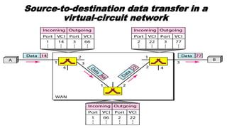
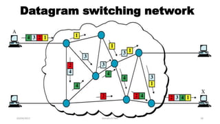


The document discusses various switching and multiple access techniques used in computer networks. It describes circuit switching, packet switching, and message switching. For packet switching, it covers virtual circuit switching and datagram switching. It also discusses different multiple access protocols like ALOHA, slotted ALOHA, CSMA, CSMA/CD, and controlled access protocols including polling, token passing, and reservation.