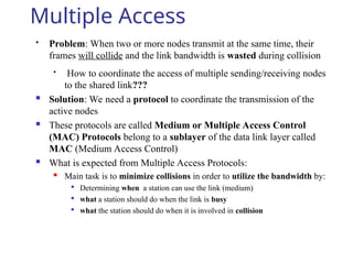
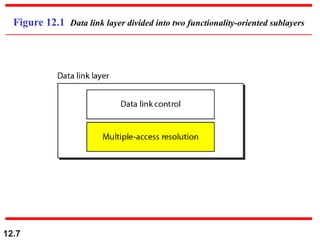
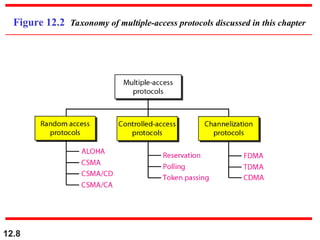
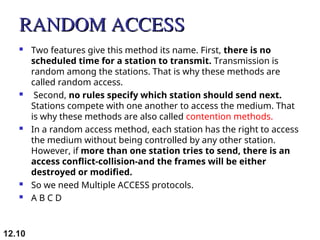
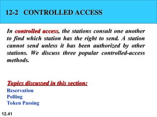
12.1
Chapter 12
Multiple Access
Copyright © The McGraw-Hill Companies, Inc. Permission required for reproduction or display.
12.2
Multiple Access
Broadcast link used in LAN consists of multiple sending and receiving nodes
connected to or use a single shared link
Broadcast links Examples
Figure 12.1 Data link layer divided into two functionality-oriented sublayers
Link Layer Control (LLC)
MAC
Responsible for error and flow control
Control
Responsible framing and MAC address
and Multiple Access Control
 We can consider the data link layer as two sublayers.
 The upper sub layer is responsible for data link control, and the
lower sublayer is responsible for resolving access to the
shared media.
 The upper sublayer that is responsible for flow and error control
is called the logical link control (LLC) layer;
 the lower sublayer that is mostly responsible for multiple access
resolution is called the media access control (MAC) layer.
 When nodes or stations are connected and use a common link,
called a multipoint or broadcast link, we need a multiple-access
protocol to coordinate access to the link.
12.5
Multiple Access
 Problem: When two or more nodes transmit at the same time, their
frames will collide and the link bandwidth is wasted during collision
 How to coordinate the access of multiple sending/receiving nodes
to the shared link???
 Solution: We need a protocol to coordinate the transmission of the
active nodes
 These protocols are called Medium or Multiple Access Control
(MAC) Protocols belong to a sublayer of the data link layer called
MAC (Medium Access Control)
 What is expected from Multiple Access Protocols:
 Main task is to minimize collisions in order to utilize the bandwidth by:

Determining when a station can use the link (medium)

what a station should do when the link is busy

what the station should do when it is involved in collision
12.7
Figure 12.1 Data link layer divided into two functionality-oriented sublayers
12.8
Figure 12.2 Taxonomy of multiple-access protocols discussed in this chapter
12.9
12-1 RANDOM ACCESS
12-1 RANDOM ACCESS
In
In random access
random access or
or contention
contention methods, no station is
methods, no station is
superior to another station and none is assigned the
control over another. No station permits, or does not
permit, another station to send. At each instance, a
station that has data to send uses a procedure defined
by the protocol to make a decision on whether or not to
send.
send.
ALOHA
Carrier Sense Multiple Access
Carrier Sense Multiple Access with Collision Detection
Carrier Sense Multiple Access with Collision Avoidance
Topics discussed in this section:
RANDOM ACCESS
RANDOM ACCESS
 Two features give this method its name. First, there is no
scheduled time for a station to transmit. Transmission is
random among the stations. That is why these methods are
called random access.
 Second, no rules specify which station should send next.
Stations compete with one another to access the medium. That
is why these methods are also called contention methods.
 In a random access method, each station has the right to access
the medium without being controlled by any other station.
However, if more than one station tries to send, there is an
access conflict-collision-and the frames will be either
destroyed or modified.
 So we need Multiple ACCESS protocols.
 A B C D
12.10
 ALOHA, the earliest random access
method, was developed at the
University of Hawaii in early 1970.
 It was designed for a radio (wireless)
LAN, but it can be used on any shared
medium.
12.12
PURE ALOHA
12.13
12.14
12.15
Figure 12.3 Frames in a pure ALOHA network
12.16
Figure 12.4 Procedure for pure ALOHA protocol
 A collision involves two or more stations. If all these
stations try to resend their frames after the time-out, the
frames will collide again.
 Pure ALOHA dictates that when the time-out period
passes, each station waits a random amount of time
before resending its frame. The randomness will help
avoid more collisions. We call this time the back-off time TB
 The back-off time TB is a random value that normally
depends on K (the number of attempted
unsuccessful transmissions).
 A B C D  TB
12.17
 In this binary exponential back-off method, for each
retransmission, a multiplier in the range 0 to 2
K
- 1 is
randomly chosen and multiplied by Tp (maximum
propagation time) or Tfr (the average time required to
send out a frame) to find TB
 Note that in this procedure, the range of the random
numbers
increases after each collision. The value of Kmax is usually
chosen as 15.
12.18
Vulnerable time for pure ALOHA protocol
12.19
PURE ALOHA
12.20
The throughput ( S) for pure ALOHA is
S = G × e
−2G
.
The maximum throughput
Smax = 0.184 when G= (1/2).
G = Average number of frames generated by the system (all stations) during one
frame transmission time
 if one-half a frame is generated during one frame
transmission time (in other words, one frame during two
frame transmission times), then 18.4 percent of these
frames reach their destination successfully.
 This is an expected result because the vulnerable time is 2
times the frame transmission time.
 Therefore, if a station generates only one frame in this
vulnerable time (and no other stations generate a frame
during this time), the frame will reach its destination
successfully
12.21
Slotted ALOHA
 Time is divided into slots equal to a frame transmission time (Tfr)
 A station can transmit at the beginning of a slot only
 If a station misses the beginning of a slot, it has to wait until the
beginning of the next time slot.
 A central clock or station informs all stations about the start of a
each slot
12.22
SLOTTED ALOHA
12.23
12.24
12.25
Figure 12.6 Frames in a slotted ALOHA network
12.26
Figure 12.7 Vulnerable time for slotted ALOHA protocol
12.27
 The throughput for slotted ALOHA is
S = G × e−G
.
 The maximum throughput
Smax = 0.368 when G = 1.
 In other words, if a frame is generated during one frame
transmission time, then 36.8 percent of these frames
reach their destination successfully.
 This result can be expected because the vulnerable time is
equal to the frame transmission time.
 Therefore, if a station generates only one frame in this
vulnerable time (and no other station generates a frame
during this time), the frame will reach its destination
successfully.
12.28
PURE ALOHA vs SLOTTED ALOHA
12.29
12.30
Figure 12.9 Vulnerable time in CSMA
12.31
Figure 12.10 Behavior of three persistence methods
12.32
Figure 12.11 Flow diagram for three persistence methods
12.33
Figure 12.12 Collision of the first bit in CSMA/CD
12.34
Figure 12.13 Collision and abortion in CSMA/CD
12.35
A network using CSMA/CD has a bandwidth of 10 Mbps.
If the maximum propagation time (including the delays in
the devices and ignoring the time needed to send a
jamming signal, as we see later) is 25.6 μs, what is the
minimum size of the frame?
Example 12.5
Solution
The frame transmission time is Tfr = 2 × Tp = 51.2 μs.
This means, in the worst case, a station needs to transmit
for a period of 51.2 μs to detect the collision. The
minimum size of the frame is 10 Mbps × 51.2 μs = 512
bits or 64 bytes. This is actually the minimum size of the
frame for Standard Ethernet.
12.36
Figure 12.14 Flow diagram for the CSMA/CD
12.37
Figure 12.15 Energy level during transmission, idleness, or collision
On a wired network, energy level is almost double during a collision.
This is how a receiver tells if there is a collision.
But on a wireless network, energy level is not that high (barely 5-10%
higher). So with wireless, we need to avoid collisions.
12.38
Figure 12.17 Flow diagram for CSMA/CA
Channel idle? Don’t transmit yet!
Wait IFS time.
Still idle after IFS? Don’t transmit yet!
Now in Contention Window.
Choose random number and wait that
many slots.
Did you wait R slots and all slots were
available? Go ahead, transmit.
Now, wait time-out for a response.
12.39
Figure 12.16 Timing in CSMA/CA
12.40
In CSMA/CA, the IFS can also be used to
define the priority of a station or a
frame.
Note
12.41
12-2 CONTROLLED ACCESS
In
In controlled access
controlled access, the stations consult one another
, the stations consult one another
to find which station has the right to send. A station
cannot send unless it has been authorized by other
stations. We discuss three popular controlled-access
methods.
methods.
Reservation
Polling
Token Passing
Topics discussed in this section:
12.42
Figure 12.18 Reservation access method
12.43
Figure 12.19 Select and poll functions in polling access method
12.44
Figure 12.20 Logical ring and physical topology in token-passing access method
12.45
12-3 CHANNELIZATION
12-3 CHANNELIZATION
Channelization
Channelization is a multiple-access method in which
is a multiple-access method in which
the available bandwidth of a link is shared in time,
frequency, or through code, between different stations.
In this section, we discuss three channelization
protocols.
protocols.
Frequency-Division Multiple Access (FDMA)
Time-Division Multiple Access (TDMA)
Code-Division Multiple Access (CDMA)
Topics discussed in this section:
12.46
We see the application of all these
methods in Chapter 16 when
we discuss cellular phone systems.
Note
12.47
Figure 12.21 Frequency-division multiple access (FDMA)
12.48
In FDMA, the available bandwidth
of the common channel is divided into
bands that are separated by guard
bands.
Note
12.49
Figure 12.22 Time-division multiple access (TDMA)
12.50
In TDMA, the bandwidth is just one
channel that is timeshared between
different stations.
Note
12.51
In CDMA, one channel carries all
transmissions simultaneously.
Note
12.52
Figure 12.23 Simple idea of communication with code
12.53
Figure 12.24 Chip sequences
12.54
Figure 12.25 Data representation in CDMA
12.55
Figure 12.26 Sharing channel in CDMA
12.56
Figure 12.27 Digital signal created by four stations in CDMA
12.57
Figure 12.28 Decoding of the composite signal for one in CDMA
12.58
Figure 12.29 General rule and examples of creating Walsh tables
12.59
The number of sequences in a Walsh
table needs to be N = 2m
.
Note
12.60
Find the chips for a network with
a. Two stations b. Four stations
Example 12.6
Solution
We can use the rows of W2 and W4 in Figure 12.29:
a. For a two-station network, we have
[+1 +1] and [+1 −1].
b. For a four-station network we have
[+1 +1 +1 +1], [+1 −1 +1 −1],
[+1 +1 −1 −1], and [+1 −1 −1 +1].
12.61
What is the number of sequences if we have 90 stations in
our network?
Example 12.7
Solution
The number of sequences needs to be 2m
. We need to
choose m = 7 and N = 27
or 128. We can then use 90
of the sequences as the chips.
12.62
Prove that a receiving station can get the data sent by a
specific sender if it multiplies the entire data on the
channel by the sender’s chip code and then divides it by
the number of stations.
Example 12.8
Solution
Let us prove this for the first station, using our previous
four-station example. We can say that the data on the
channel
D = (d1 c
⋅ 1 + d2 c
⋅ 2 + d3 c
⋅ 3 + d4 c
⋅ 4).
The receiver which wants to get the data sent by station 1
multiplies these data by c1.
12.63
Example 12.8 (continued)
When we divide the result by N, we get d1 .

Multiple Access protocols IN COMPUTER NETWORKS.ppt

  • 1.
    12.1 Chapter 12 Multiple Access Copyright© The McGraw-Hill Companies, Inc. Permission required for reproduction or display.
  • 2.
  • 3.
    Multiple Access Broadcast linkused in LAN consists of multiple sending and receiving nodes connected to or use a single shared link Broadcast links Examples
  • 4.
    Figure 12.1 Datalink layer divided into two functionality-oriented sublayers Link Layer Control (LLC) MAC Responsible for error and flow control Control Responsible framing and MAC address and Multiple Access Control
  • 5.
     We canconsider the data link layer as two sublayers.  The upper sub layer is responsible for data link control, and the lower sublayer is responsible for resolving access to the shared media.  The upper sublayer that is responsible for flow and error control is called the logical link control (LLC) layer;  the lower sublayer that is mostly responsible for multiple access resolution is called the media access control (MAC) layer.  When nodes or stations are connected and use a common link, called a multipoint or broadcast link, we need a multiple-access protocol to coordinate access to the link. 12.5
  • 6.
    Multiple Access  Problem:When two or more nodes transmit at the same time, their frames will collide and the link bandwidth is wasted during collision  How to coordinate the access of multiple sending/receiving nodes to the shared link???  Solution: We need a protocol to coordinate the transmission of the active nodes  These protocols are called Medium or Multiple Access Control (MAC) Protocols belong to a sublayer of the data link layer called MAC (Medium Access Control)  What is expected from Multiple Access Protocols:  Main task is to minimize collisions in order to utilize the bandwidth by:  Determining when a station can use the link (medium)  what a station should do when the link is busy  what the station should do when it is involved in collision
  • 7.
    12.7 Figure 12.1 Datalink layer divided into two functionality-oriented sublayers
  • 8.
    12.8 Figure 12.2 Taxonomyof multiple-access protocols discussed in this chapter
  • 9.
    12.9 12-1 RANDOM ACCESS 12-1RANDOM ACCESS In In random access random access or or contention contention methods, no station is methods, no station is superior to another station and none is assigned the superior to another station and none is assigned the control over another. No station permits, or does not control over another. No station permits, or does not permit, another station to send. At each instance, a permit, another station to send. At each instance, a station that has data to send uses a procedure defined station that has data to send uses a procedure defined by the protocol to make a decision on whether or not to by the protocol to make a decision on whether or not to send. send. ALOHA Carrier Sense Multiple Access Carrier Sense Multiple Access with Collision Detection Carrier Sense Multiple Access with Collision Avoidance Topics discussed in this section: Topics discussed in this section:
  • 10.
    RANDOM ACCESS RANDOM ACCESS Two features give this method its name. First, there is no scheduled time for a station to transmit. Transmission is random among the stations. That is why these methods are called random access.  Second, no rules specify which station should send next. Stations compete with one another to access the medium. That is why these methods are also called contention methods.  In a random access method, each station has the right to access the medium without being controlled by any other station. However, if more than one station tries to send, there is an access conflict-collision-and the frames will be either destroyed or modified.  So we need Multiple ACCESS protocols.  A B C D 12.10
  • 11.
     ALOHA, theearliest random access method, was developed at the University of Hawaii in early 1970.  It was designed for a radio (wireless) LAN, but it can be used on any shared medium. 12.12
  • 12.
  • 13.
  • 14.
    12.15 Figure 12.3 Framesin a pure ALOHA network
  • 15.
    12.16 Figure 12.4 Procedurefor pure ALOHA protocol
  • 16.
     A collisioninvolves two or more stations. If all these stations try to resend their frames after the time-out, the frames will collide again.  Pure ALOHA dictates that when the time-out period passes, each station waits a random amount of time before resending its frame. The randomness will help avoid more collisions. We call this time the back-off time TB  The back-off time TB is a random value that normally depends on K (the number of attempted unsuccessful transmissions).  A B C D  TB 12.17
  • 17.
     In thisbinary exponential back-off method, for each retransmission, a multiplier in the range 0 to 2 K - 1 is randomly chosen and multiplied by Tp (maximum propagation time) or Tfr (the average time required to send out a frame) to find TB  Note that in this procedure, the range of the random numbers increases after each collision. The value of Kmax is usually chosen as 15. 12.18
  • 18.
    Vulnerable time forpure ALOHA protocol 12.19
  • 19.
    PURE ALOHA 12.20 The throughput( S) for pure ALOHA is S = G × e −2G . The maximum throughput Smax = 0.184 when G= (1/2). G = Average number of frames generated by the system (all stations) during one frame transmission time
  • 20.
     if one-halfa frame is generated during one frame transmission time (in other words, one frame during two frame transmission times), then 18.4 percent of these frames reach their destination successfully.  This is an expected result because the vulnerable time is 2 times the frame transmission time.  Therefore, if a station generates only one frame in this vulnerable time (and no other stations generate a frame during this time), the frame will reach its destination successfully 12.21
  • 21.
    Slotted ALOHA  Timeis divided into slots equal to a frame transmission time (Tfr)  A station can transmit at the beginning of a slot only  If a station misses the beginning of a slot, it has to wait until the beginning of the next time slot.  A central clock or station informs all stations about the start of a each slot 12.22
  • 22.
  • 23.
  • 24.
    12.25 Figure 12.6 Framesin a slotted ALOHA network
  • 25.
    12.26 Figure 12.7 Vulnerabletime for slotted ALOHA protocol
  • 26.
    12.27  The throughputfor slotted ALOHA is S = G × e−G .  The maximum throughput Smax = 0.368 when G = 1.
  • 27.
     In otherwords, if a frame is generated during one frame transmission time, then 36.8 percent of these frames reach their destination successfully.  This result can be expected because the vulnerable time is equal to the frame transmission time.  Therefore, if a station generates only one frame in this vulnerable time (and no other station generates a frame during this time), the frame will reach its destination successfully. 12.28
  • 28.
    PURE ALOHA vsSLOTTED ALOHA 12.29
  • 29.
  • 30.
    12.31 Figure 12.10 Behaviorof three persistence methods
  • 31.
    12.32 Figure 12.11 Flowdiagram for three persistence methods
  • 32.
    12.33 Figure 12.12 Collisionof the first bit in CSMA/CD
  • 33.
    12.34 Figure 12.13 Collisionand abortion in CSMA/CD
  • 34.
    12.35 A network usingCSMA/CD has a bandwidth of 10 Mbps. If the maximum propagation time (including the delays in the devices and ignoring the time needed to send a jamming signal, as we see later) is 25.6 μs, what is the minimum size of the frame? Example 12.5 Solution The frame transmission time is Tfr = 2 × Tp = 51.2 μs. This means, in the worst case, a station needs to transmit for a period of 51.2 μs to detect the collision. The minimum size of the frame is 10 Mbps × 51.2 μs = 512 bits or 64 bytes. This is actually the minimum size of the frame for Standard Ethernet.
  • 35.
    12.36 Figure 12.14 Flowdiagram for the CSMA/CD
  • 36.
    12.37 Figure 12.15 Energylevel during transmission, idleness, or collision On a wired network, energy level is almost double during a collision. This is how a receiver tells if there is a collision. But on a wireless network, energy level is not that high (barely 5-10% higher). So with wireless, we need to avoid collisions.
  • 37.
    12.38 Figure 12.17 Flowdiagram for CSMA/CA Channel idle? Don’t transmit yet! Wait IFS time. Still idle after IFS? Don’t transmit yet! Now in Contention Window. Choose random number and wait that many slots. Did you wait R slots and all slots were available? Go ahead, transmit. Now, wait time-out for a response.
  • 38.
  • 39.
    12.40 In CSMA/CA, theIFS can also be used to define the priority of a station or a frame. Note
  • 40.
    12.41 12-2 CONTROLLED ACCESS 12-2CONTROLLED ACCESS In In controlled access controlled access, the stations consult one another , the stations consult one another to find which station has the right to send. A station to find which station has the right to send. A station cannot send unless it has been authorized by other cannot send unless it has been authorized by other stations. We discuss three popular controlled-access stations. We discuss three popular controlled-access methods. methods. Reservation Polling Token Passing Topics discussed in this section: Topics discussed in this section:
  • 41.
  • 42.
    12.43 Figure 12.19 Selectand poll functions in polling access method
  • 43.
    12.44 Figure 12.20 Logicalring and physical topology in token-passing access method
  • 44.
    12.45 12-3 CHANNELIZATION 12-3 CHANNELIZATION Channelization Channelizationis a multiple-access method in which is a multiple-access method in which the available bandwidth of a link is shared in time, the available bandwidth of a link is shared in time, frequency, or through code, between different stations. frequency, or through code, between different stations. In this section, we discuss three channelization In this section, we discuss three channelization protocols. protocols. Frequency-Division Multiple Access (FDMA) Time-Division Multiple Access (TDMA) Code-Division Multiple Access (CDMA) Topics discussed in this section: Topics discussed in this section:
  • 45.
    12.46 We see theapplication of all these methods in Chapter 16 when we discuss cellular phone systems. Note
  • 46.
  • 47.
    12.48 In FDMA, theavailable bandwidth of the common channel is divided into bands that are separated by guard bands. Note
  • 48.
    12.49 Figure 12.22 Time-divisionmultiple access (TDMA)
  • 49.
    12.50 In TDMA, thebandwidth is just one channel that is timeshared between different stations. Note
  • 50.
    12.51 In CDMA, onechannel carries all transmissions simultaneously. Note
  • 51.
    12.52 Figure 12.23 Simpleidea of communication with code
  • 52.
  • 53.
    12.54 Figure 12.25 Datarepresentation in CDMA
  • 54.
  • 55.
    12.56 Figure 12.27 Digitalsignal created by four stations in CDMA
  • 56.
    12.57 Figure 12.28 Decodingof the composite signal for one in CDMA
  • 57.
    12.58 Figure 12.29 Generalrule and examples of creating Walsh tables
  • 58.
    12.59 The number ofsequences in a Walsh table needs to be N = 2m . Note
  • 59.
    12.60 Find the chipsfor a network with a. Two stations b. Four stations Example 12.6 Solution We can use the rows of W2 and W4 in Figure 12.29: a. For a two-station network, we have [+1 +1] and [+1 −1]. b. For a four-station network we have [+1 +1 +1 +1], [+1 −1 +1 −1], [+1 +1 −1 −1], and [+1 −1 −1 +1].
  • 60.
    12.61 What is thenumber of sequences if we have 90 stations in our network? Example 12.7 Solution The number of sequences needs to be 2m . We need to choose m = 7 and N = 27 or 128. We can then use 90 of the sequences as the chips.
  • 61.
    12.62 Prove that areceiving station can get the data sent by a specific sender if it multiplies the entire data on the channel by the sender’s chip code and then divides it by the number of stations. Example 12.8 Solution Let us prove this for the first station, using our previous four-station example. We can say that the data on the channel D = (d1 c ⋅ 1 + d2 c ⋅ 2 + d3 c ⋅ 3 + d4 c ⋅ 4). The receiver which wants to get the data sent by station 1 multiplies these data by c1.
  • 62.
    12.63 Example 12.8 (continued) Whenwe divide the result by N, we get d1 .