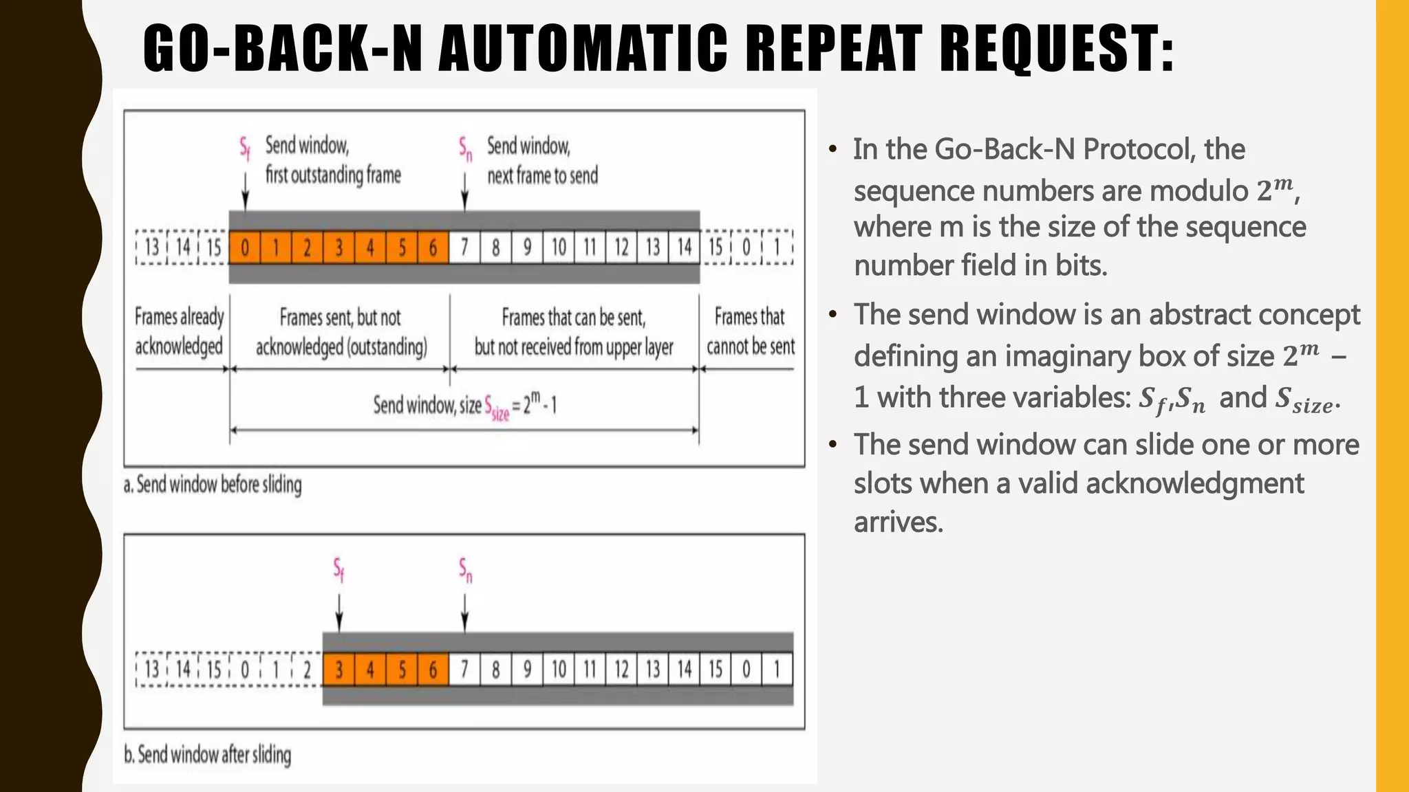
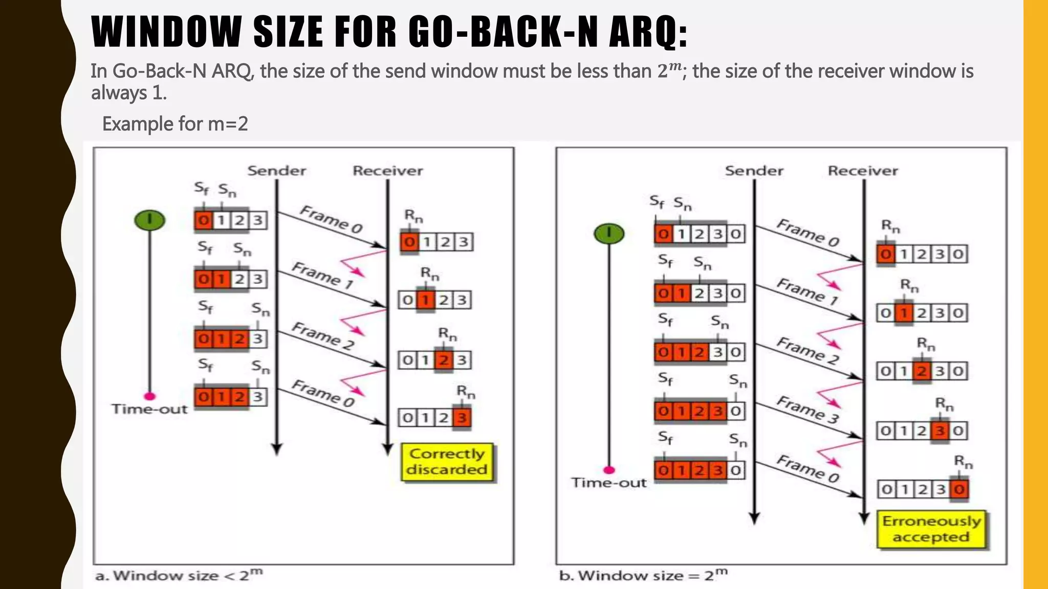
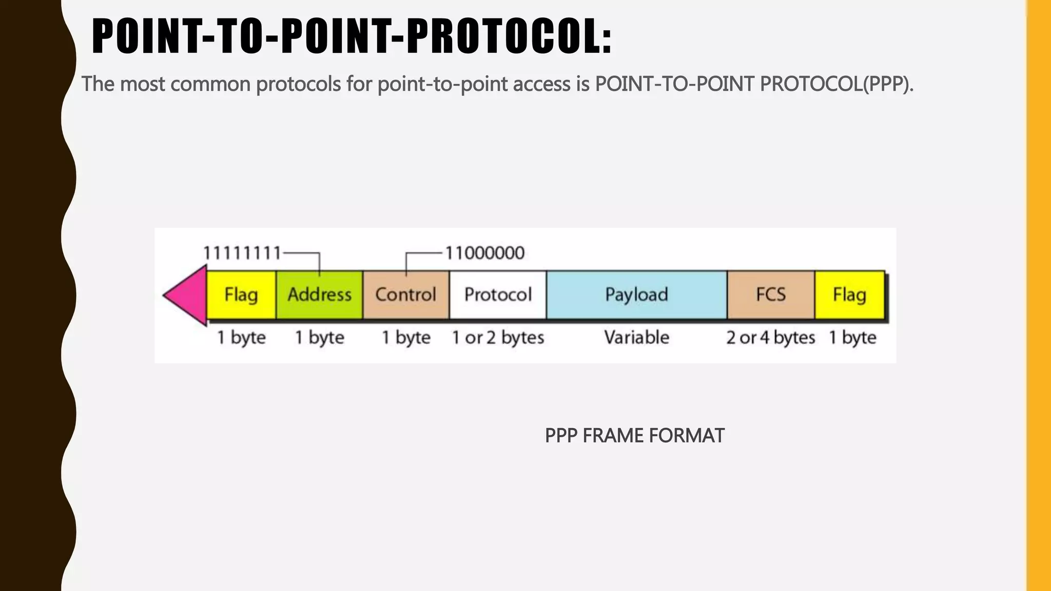
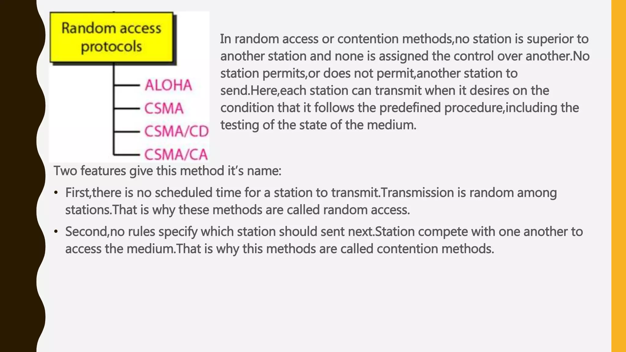
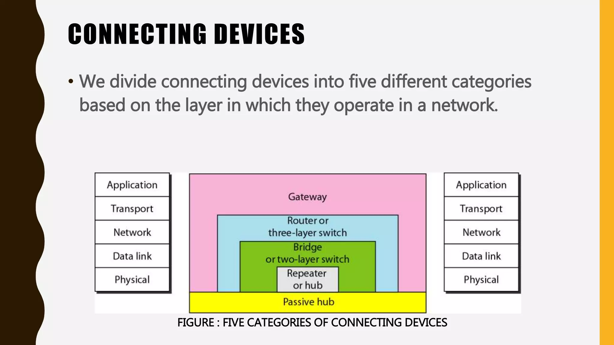
2. • Data can be corrupted during transmission. For reliable
communication, errors must be detected and corrected.
• Error detection and correction are implemented either at
data link layer or the transport layer of the OSI model.
3. TYPES OF ERRORS:
• Single bit error :-
- Only one bit in the data unit has
changed.
• Burst error :-
- It means that two or more bits in the
data unit has changed.
5. BLOCK CODES:
• In block coding we divide our message into blocks, each of k bits , called
datawords. We add r redundant bits to each block to make the length n
= k+r. The resulting n-bits blocks are called codewords.
8. LINEAR BLOCK CODES:
• Almost all block codes used today belong to a subset called linear block
codes. A linear block code is a code in which the exclusive OR (addition
modulo-2) of two valid codewords creates another valid codeword.
• Eg. Simple Parity Check Code & Hamming Code
9. SIMPLE PARITY-CHECK CODE:
• It is the simplest technique for detecting and correcting
errors. The MSB of an 8-bits word is used as the parity bit
and the remaining 7 bits are used as data or message
bits. The parity of 8-bits transmitted word can be either
even parity or odd parity.
10. • Even parity -- Even parity means the number of 1's in the given word
including the parity bit should be even (2,4,6,....).
• Odd parity -- Odd parity means the number of 1's in the given word
including the parity bit should be odd (1,3,5,....).
12. HAMMING CODE:
• In the Hamming code, k parity bits are added to an n-bit data word,
forming a new word of n + k bits. The bit positions are numbered in
sequence from 1 to n + k. Those positions numbered with powers of
two are reserved for the parity bits. The remaining bits are the data bits.
The code can be used with words of any length
15. CYCLIC CODES:
• Cyclic codes are special linear block codes with one extra property. In a
cyclic code, if a codeword is cyclically shifted (rotated), the result is
another codeword.
19. CHECKSUM:
• A checksum or hash sum is a small-size datum from a block of digital
data for the purpose of detecting errors which may have been
introduced during its transmission or storage. It is usually applied to an
installation file after it is received from the download server
22. STOP AND WAIT AUTOMATIC REPEAT REQUEST:
Stop and Wait Automatic Repeat Request Protocol adds a simple error mechanism to the Stop
and Wait Protocol.
23. • Consider the example in the figure:
• Frame0 is sent and acknowledgement
is received.
• Frame1 is lost and is resent after
time-out.
• The resent frame is acknowledged
and the timer stops.
• Frame0 is sent and acknowledged,but
acknowledgement is lost.
• The sender has no idea if the frame or
acknowledgement is lost,so after
time-out,it resends frame0,which is
acknowledged.
24. GO-BACK-N AUTOMATIC REPEAT REQUEST:
• To improve the efficiency of
transmission,multiple frames must
be in transition while waiting for
acknowledgement.
• In Go-back-N automatic repeat
request we can send several frames
before receiving
acknowledgements,we keep a copy
of these frames until the
acknowledgements arrive.
25. GO-BACK-N AUTOMATIC REPEAT REQUEST:
• In the Go-Back-N Protocol, the
sequence numbers are modulo 𝟐 𝒎,
where m is the size of the sequence
number field in bits.
• The send window is an abstract concept
defining an imaginary box of size 𝟐 𝒎 −
1 with three variables: 𝑺 𝒇,𝑺 𝒏 and 𝑺 𝒔𝒊𝒛𝒆.
• The send window can slide one or more
slots when a valid acknowledgment
arrives.
26. GO-BACK-N AUTOMATIC REPEAT REQUEST:
The receive window is an abstract
concept defining an imaginary box of size
1 with one single variable 𝑹 𝒏. The
window slides when a correct frame has
arrived; sliding occurs one slot at a time.
27. WINDOW SIZE FOR GO-BACK-N ARQ:
In Go-Back-N ARQ, the size of the send window must be less than 𝟐 𝒎
; the size of the receiver window is
always 1.
Example for m=2
29. In random access or contention methods,no station is superior to
another station and none is assigned the control over another.No
station permits,or does not permit,another station to
send.Here,each station can transmit when it desires on the
condition that it follows the predefined procedure,including the
testing of the state of the medium.
Two features give this method it’s name:
• First,there is no scheduled time for a station to transmit.Transmission is random among
stations.That is why these methods are called random access.
• Second,no rules specify which station should sent next.Station compete with one another to
access the medium.That is why this methods are called contention methods.
31. PURE ALOHA: Vulnerable Time for Pure Aloha:
The throughput for pure ALOHA is S = G ×𝒆−𝟐𝑮
The maximum throughput 𝑺 𝒎𝒂𝒙 = 0.184
when G= (1/2)
32. SLOTTED ALOHA: Vulnerable Time for Slotted Aloha:
The throughput for pure ALOHA is S = G ×𝒆−𝑮
The maximum throughput 𝑺 𝒎𝒂𝒙 = 0.368
when G=1
33. CSMA: CARRIER SENSE MULTIPLE ACCESS:
The CSMA protocol operates on the principle of carrier sensing.In this protocol,a station listens to
see the presence of transmission (carrier) on the cable and decides to act accordingly.
34. CSMA/CD: CSMA WITH COLLISION DETECTION:
If two stations sense the channel to be
idle and begin transmitting
simultaneously,they both will detect
the collision almost
immediately.Rather than transmitting
their frames further,they will stop
transmitting as soon as the collision is
detected.Quickly terminating damaged
frames saves time and bandwidth.This
is known as CSMA/CD.
35. CSMA/CA: CSMA WITH COLLISION AVOIDANCE:
Collisions are avoided through the use of
CSMA/CA ‘s three strategies:
• Interframe space
• Contention window
• Acknowledgements
36. CONTROLLED ACCESS:
• In controlled access, the stations consult one another to find
which station has the right to send. A station cannot send
unless it has been authorized by other stations.
• We discuss three popular controlled-access methods.
i. Reservation
ii. Polling
iii. Token Passing
37. 1.RESERVATION
• In the reservation method, a station needs to make a
reservation before sending data. Time is divided into intervals.
In each interval, a reservation frame precedes the data frames
sent in the interval.
FIGURE : RESERVATION ACCESS
METHOD
38. 2.POLLING
• Polling works with topologies in which one device
is designated as a primary station and the other
devices are secondary stations.
• The primary device controls the link, the secondary
devices follow its instruction.
• If the primary wants to receive data, it asks the
secondaries if they have anything to send; this is
called poll function.
39. • If the primary wants to send data, it tells the secondary to get ready to
receive; this is called select function.
FIGURE : SELECT AND POLL FUNCTIONS IN POLLING ACCESS
METHOD
40. 3.TOKEN PASSING
• In the token passing method, the station in a network are
organized in a logical ring. In other words, for each station,
there is a predecessor and a successor.
41. FIGURE : LOGICAL RING AND PHYSICAL TOPOLOGY IN TOKEN-PASSING ACCESS
METHOD
42. STANDARD ETHERNET
• The original Ethernet was created in 1976 at Xerox’s Palo Alto
Research Center (PARC). Since then, it has gone through four
generations. We briefly discuss the Standard (or traditional)
Ethernet in this section.
44. MAC SUBLAYER
• In Standard Ethernet , the MAC governs the operation of the access method. It also
frames data received from the upper layer and passes them to the physical layer.
45. FRAME FORMAT
• The Ethernet contains seven fields :
Preamble , SFD , DA , SA , length or type of protocol data
unit (PDU) , upper-layer data , and the CRC.
FIGURE : 802.3 MAC FRAME
46. CONNECTING DEVICES
• We divide connecting devices into five different categories
based on the layer in which they operate in a network.
FIGURE : FIVE CATEGORIES OF CONNECTING DEVICES
47. • We have the topics to discuss are as follows:
1. Passive hubs.
2. Repeaters.
3. Active hubs.
4. Bridges.
5. Two – Layer Switches.
6. Routers.
7. Three-Layer Switches.
8. Gateway.
48. 1.PASSIVE HUBS
• A passive hub is just a connector. It connects the wires coming
from different branches. In a star-topology Ethernet LAN, a
passive hub is just a point where the signals coming from
different stations collide; the hub is the collision point. This
type of a hub is part of the media; its location is the Internet
model is below the physical layer.
49. 2.REPEATERS
• A repeater is a device that operates only in the physical layer.
• A repeater connects two segments of a LAN.
• A repeater forwards every frame.
• A repeater is a regenerator , not an amplifier.
50. FIGURE : A REPEATER CONNECTING TWO SEGMENTS OF A
LAN
52. 3.ACTIVE HUBS
• An active hub is actually a multiport repeater. It is normally used to create connections
between stations in a physical star topology.
53. 4.BRIDGES
• A bridge operates in both the physical and the data link layer. As a physical layer device,
it regenerates the signal as it receives. As a data link layer device, the bridge can check
the physical (MAC) addresses (source and destination) contained in the frame.
55. 5.TWO-LAYER SWITCHES
• In this , we can have a two-layer switch or a three-layer switch. A
three-layer switch is used at the network layer; it is a kind of router.
The two-layer switch performs at the physical and data link layers.
• A two-layer switch is a bridge, a bridge with many ports and a
design that allows better (faster) performance.
• A two-layer switch, as a bridge does, makes a filtering decision
based on the MAC address of the frame it received.
56. 6.ROUTERS
• A router is a three-layer device that routes packets based on
their logical addresses (host-to-host addressing). A router
normally connects LANs and WANs in the Internet and has a
routing table that is used for making decisions about the route.
The routing tables are normally dynamic and are updated using
routing protocols.
58. 7.THREE-LAYER SWITCHES
• A three-layer switch is a router , but a faster and more sophisticated. The switching fabric
in a three-layer switch allows faster table lookup and forwarding.
59. 8.GATEWAY
• A gateway is normally a computer that operates in all five layers of the Internet or seven
layers of OSI model. A gateway takes an application message ,reads it, and interprets it.
This means that it can be used as a connecting device between two internetworks that
use different models.