This document provides an overview of LabVIEW programming techniques, including:
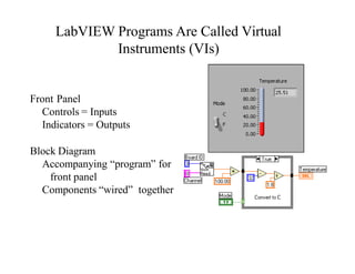
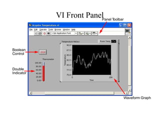
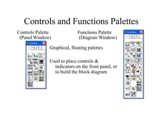
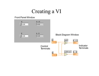
1. LabVIEW programs are called virtual instruments (VIs) that have a front panel (with controls and indicators) and a block diagram (with components wired together).
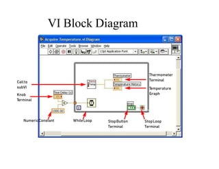
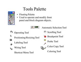
2. The block diagram uses controls, functions, and indicators accessed through palettes to build the program logic. Tools are used to operate and modify the front panel and block diagram objects.
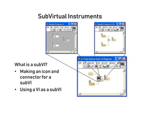
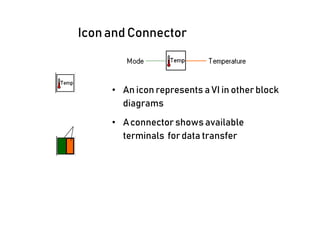
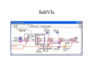
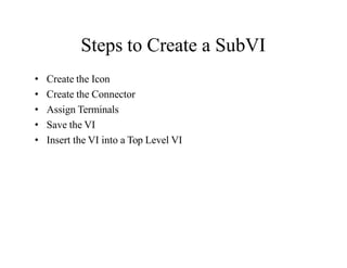
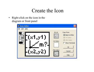
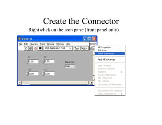
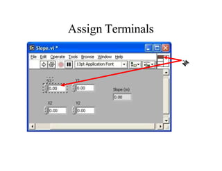
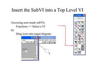
3. SubVIs allow creating modular and reusable code segments by making an icon and connector for a VI, then using it within another VI to avoid recreating code.