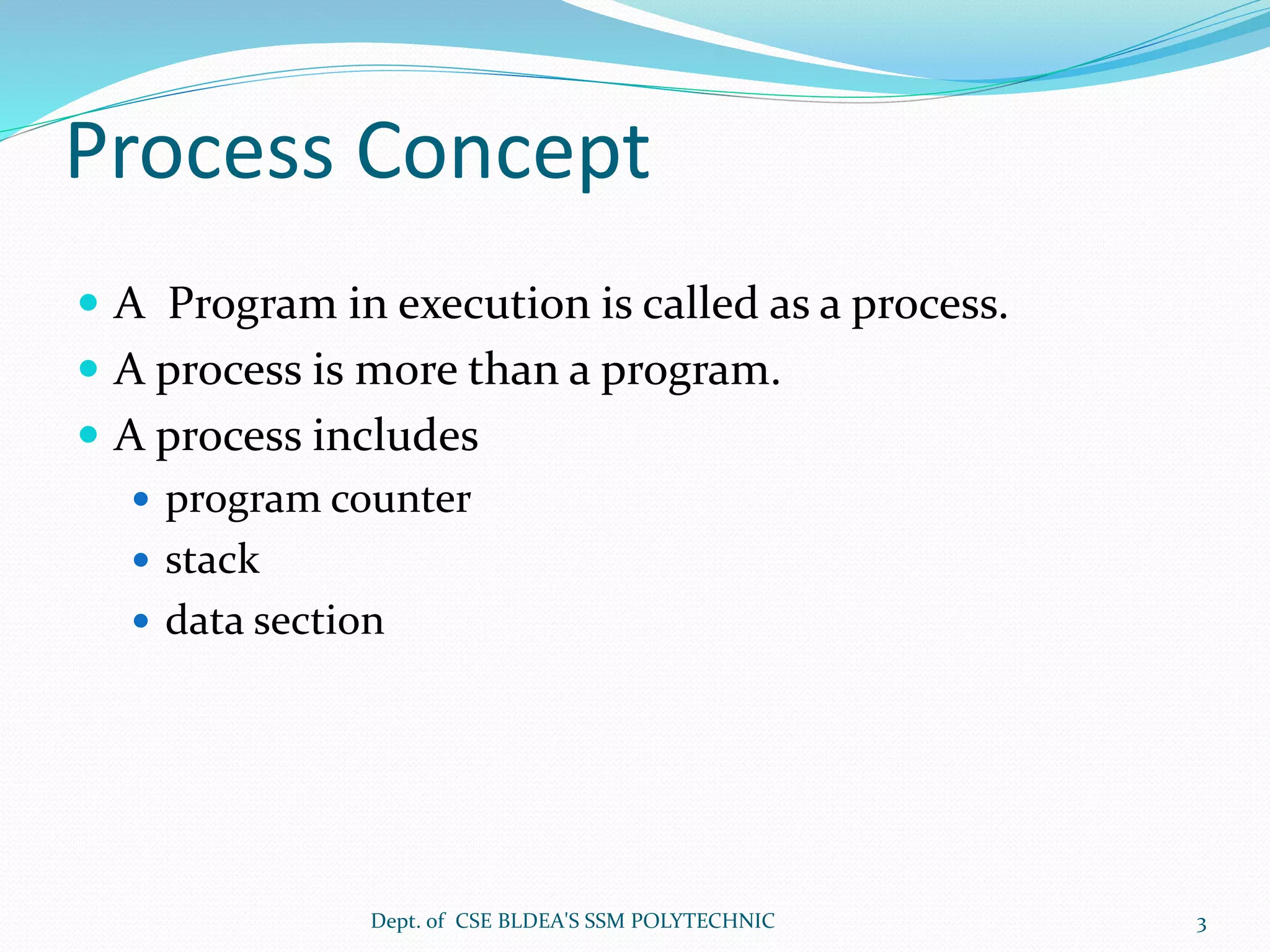
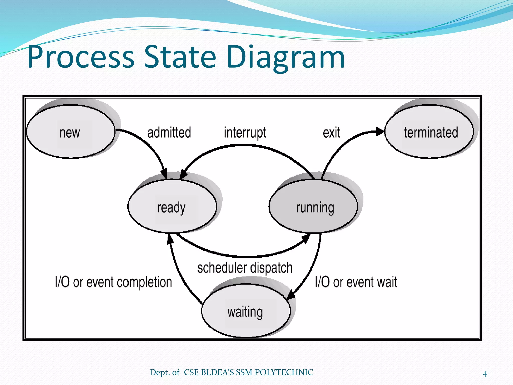
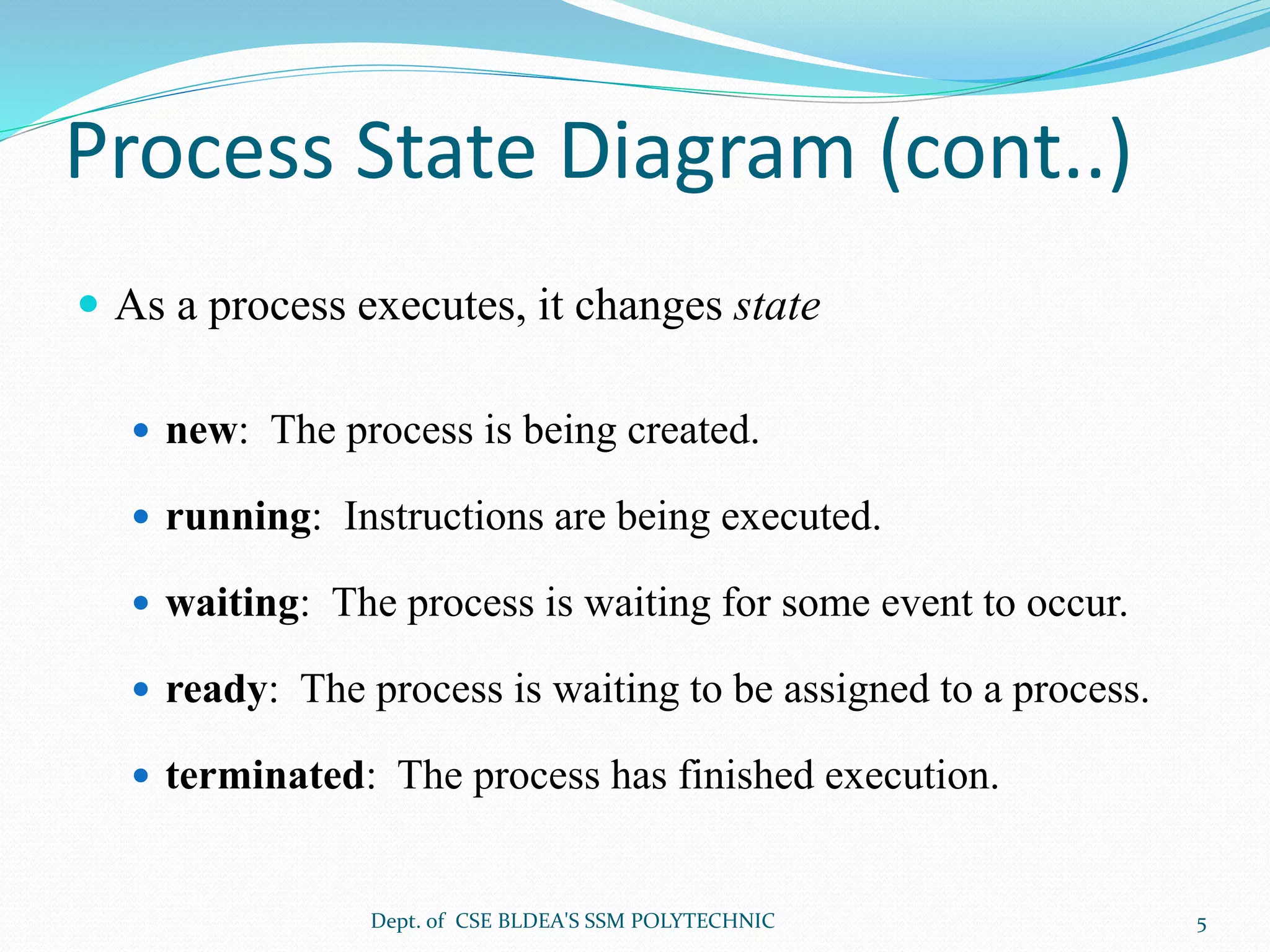
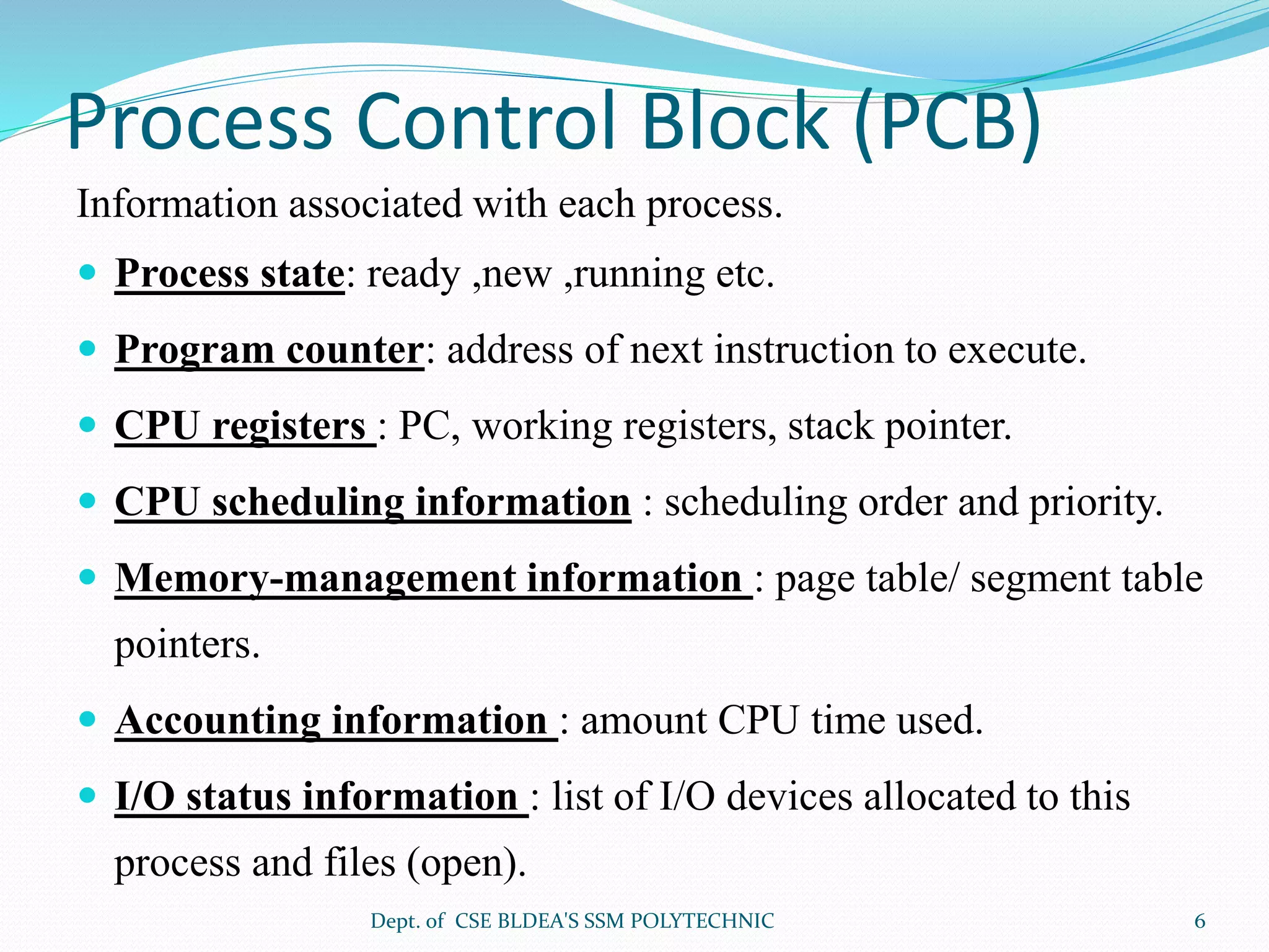
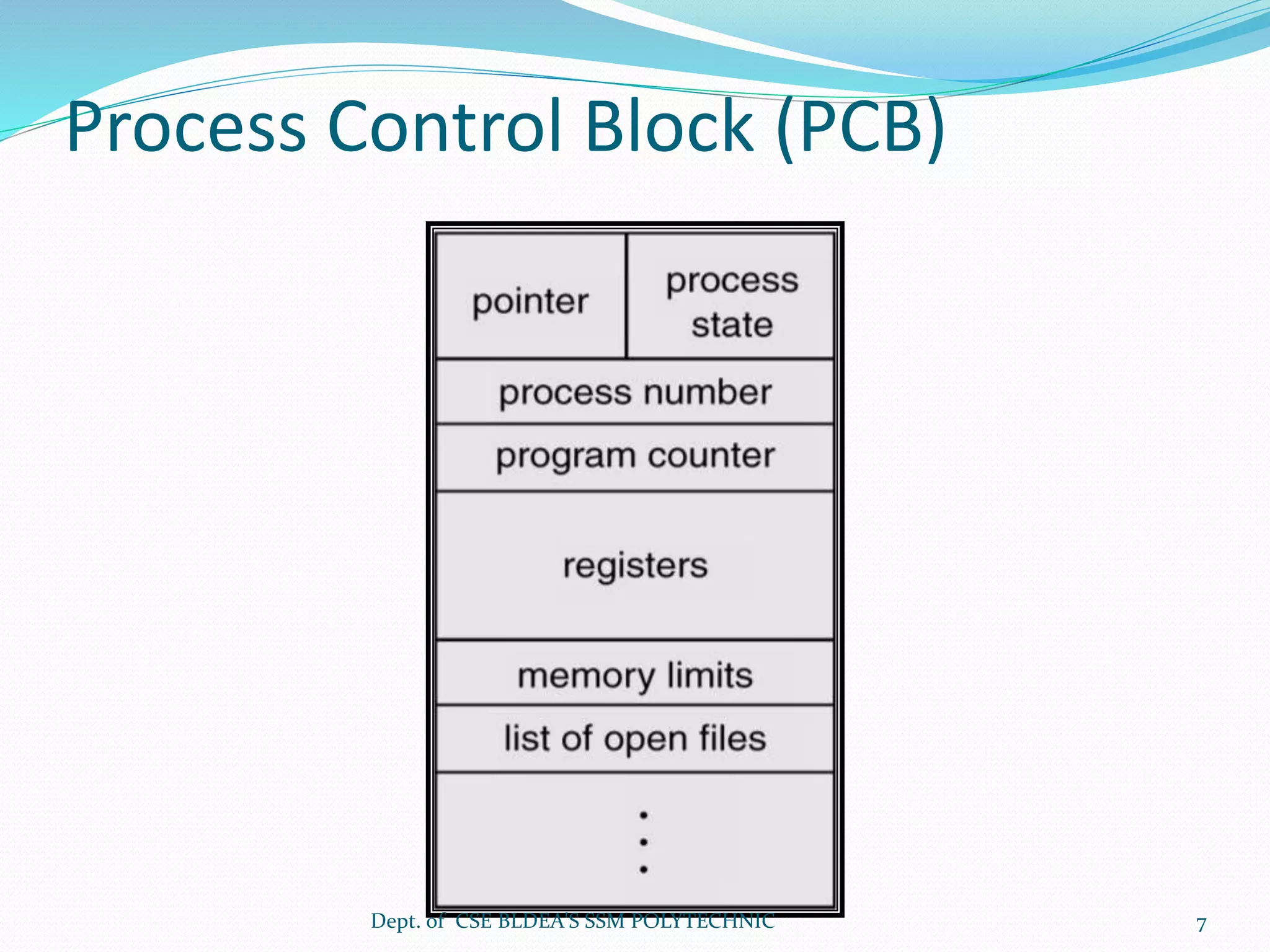
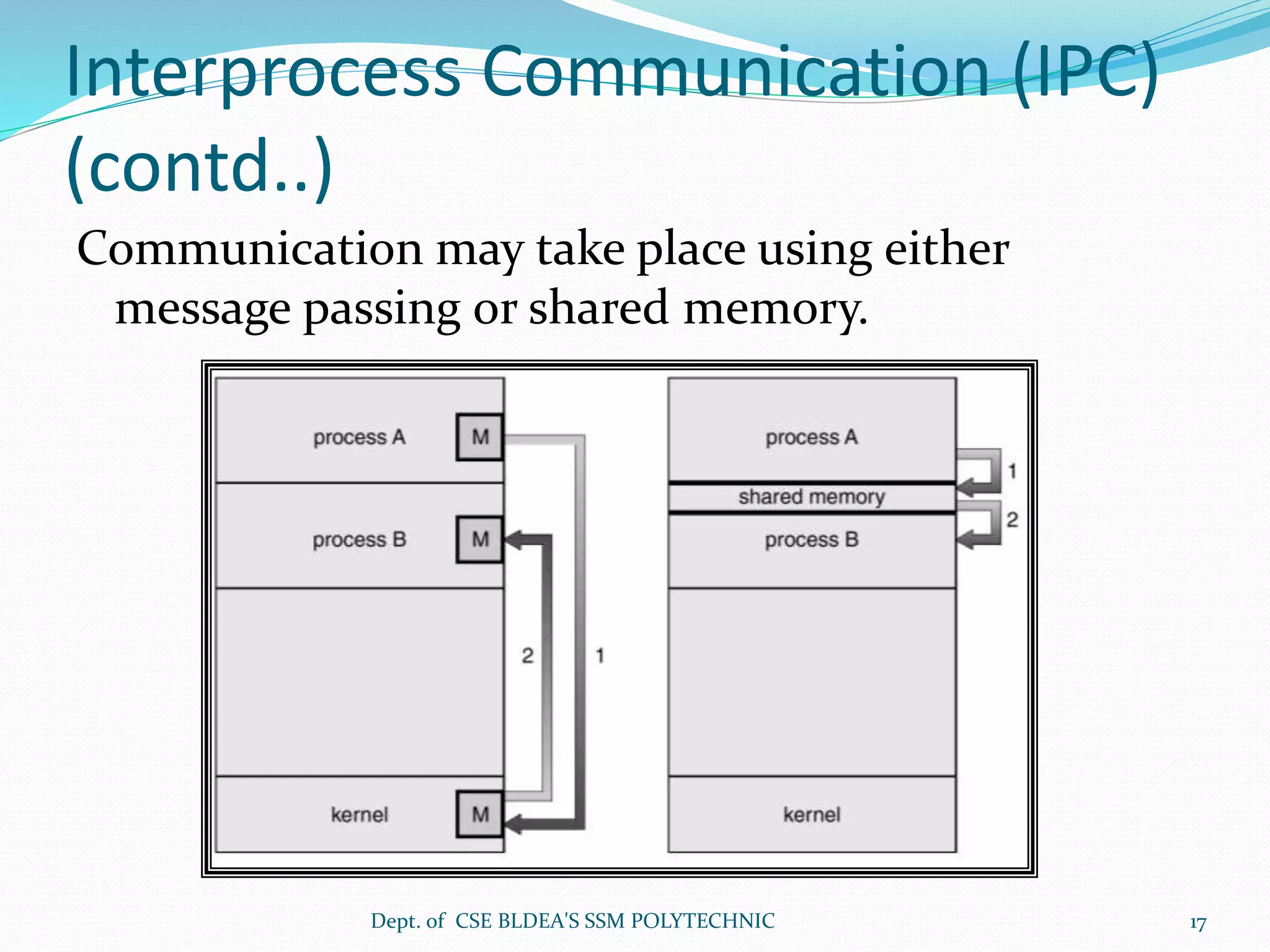
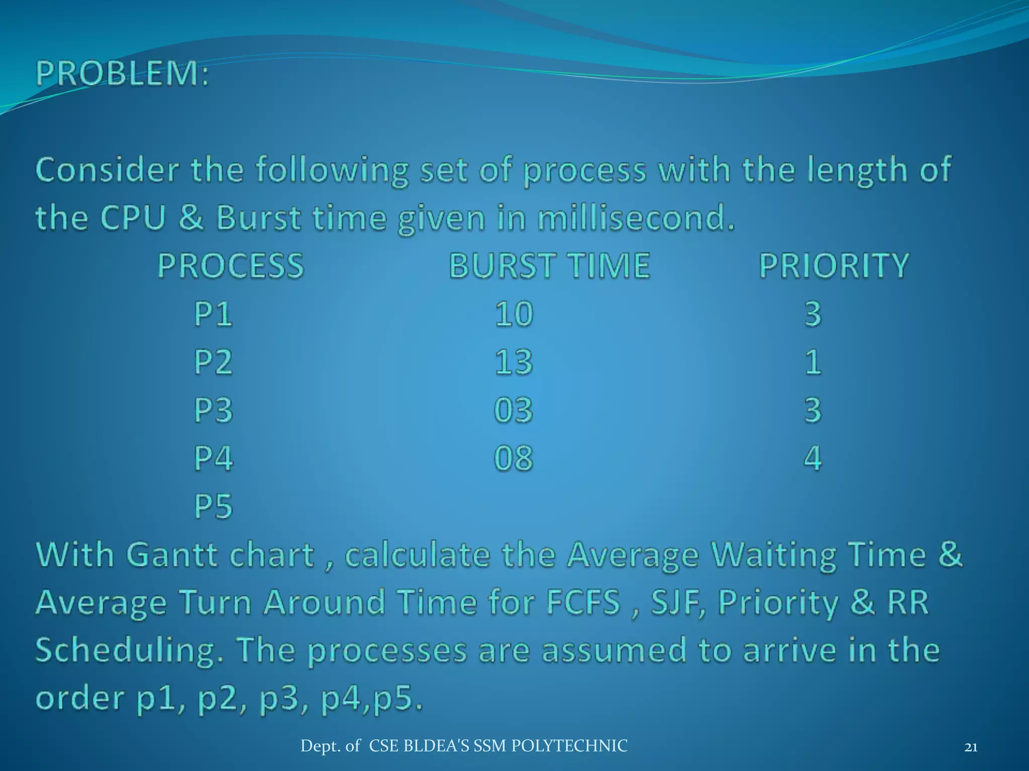
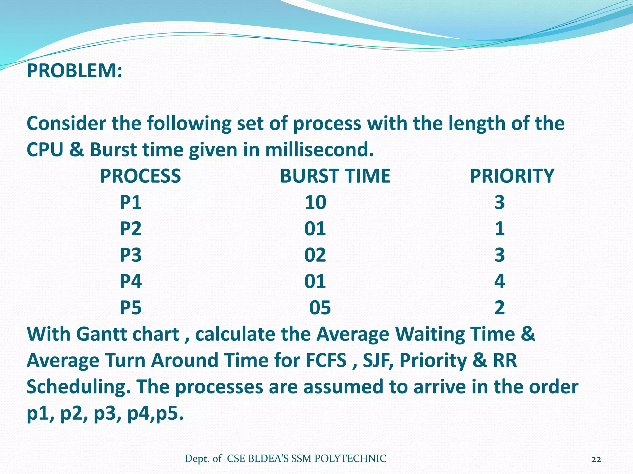
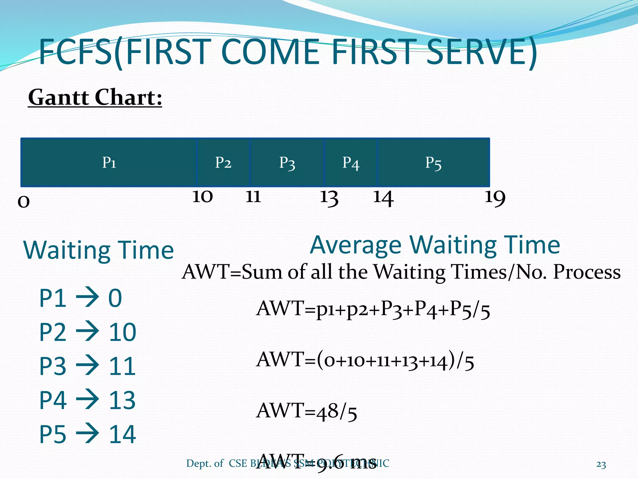
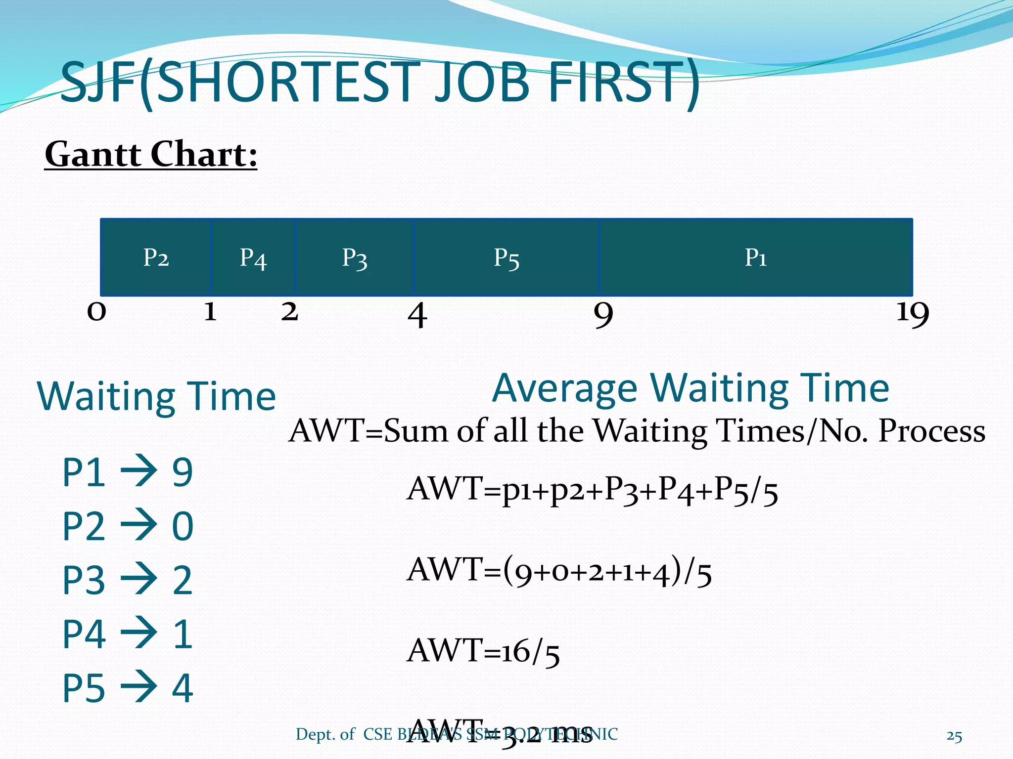
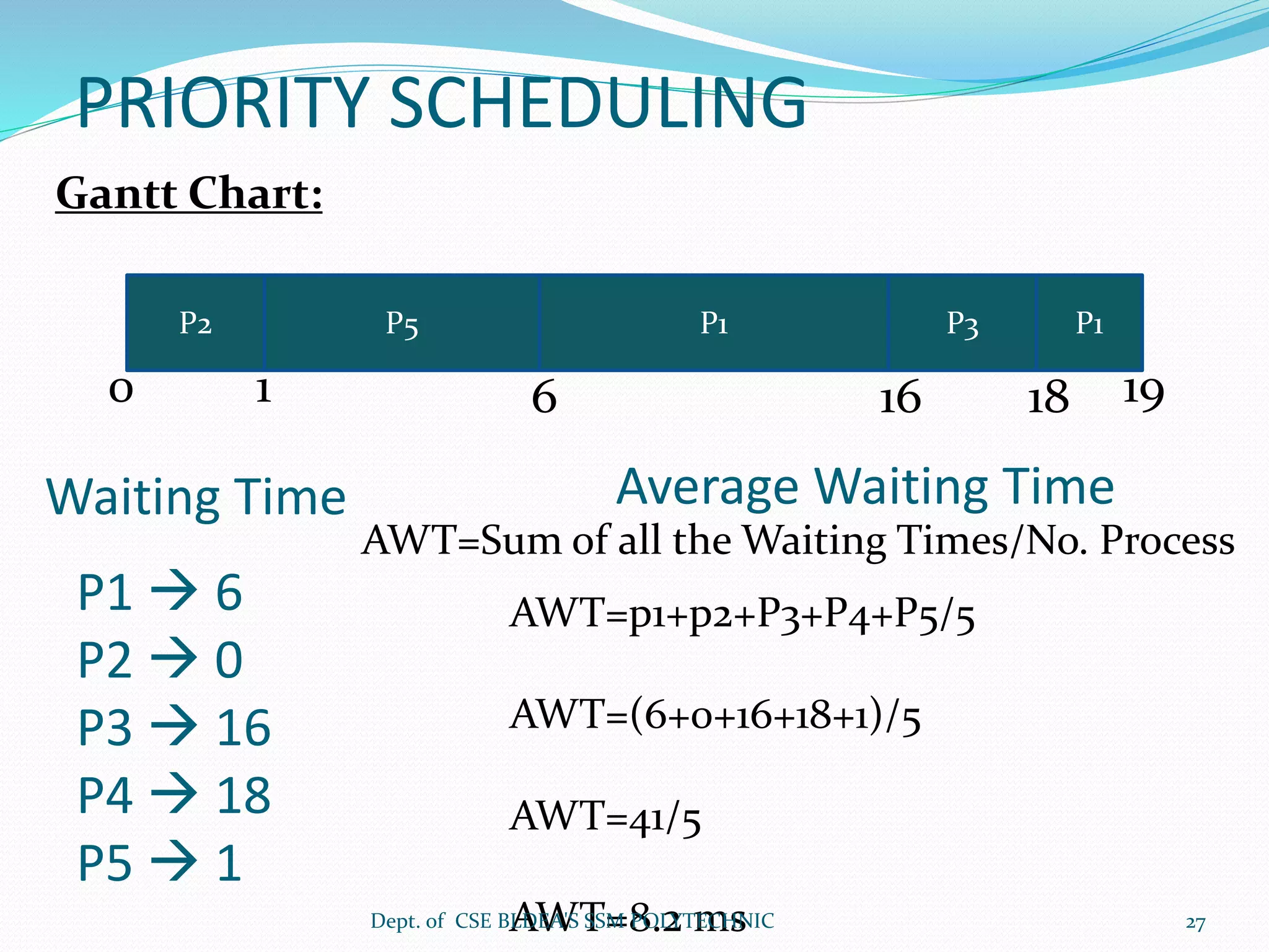
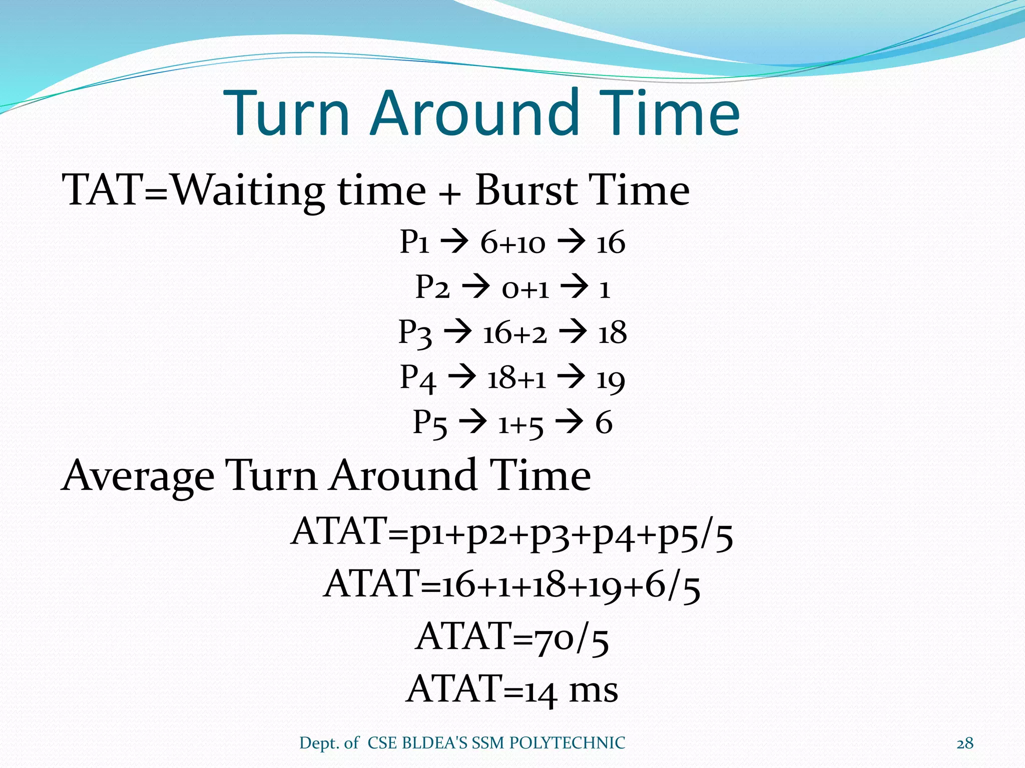
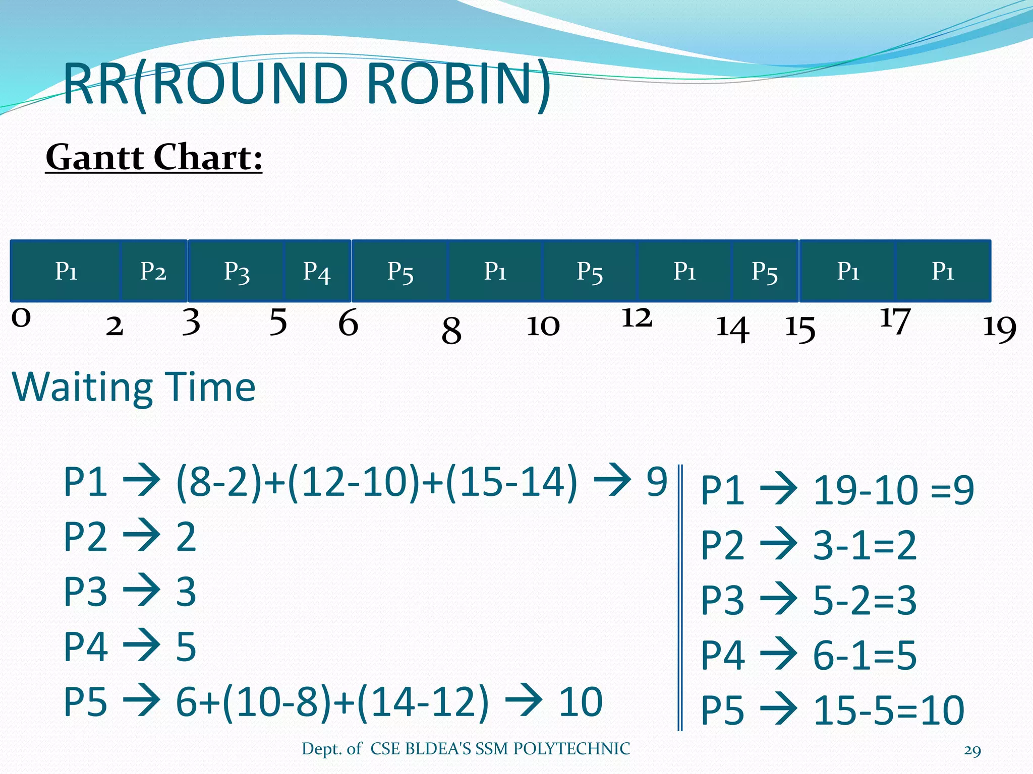
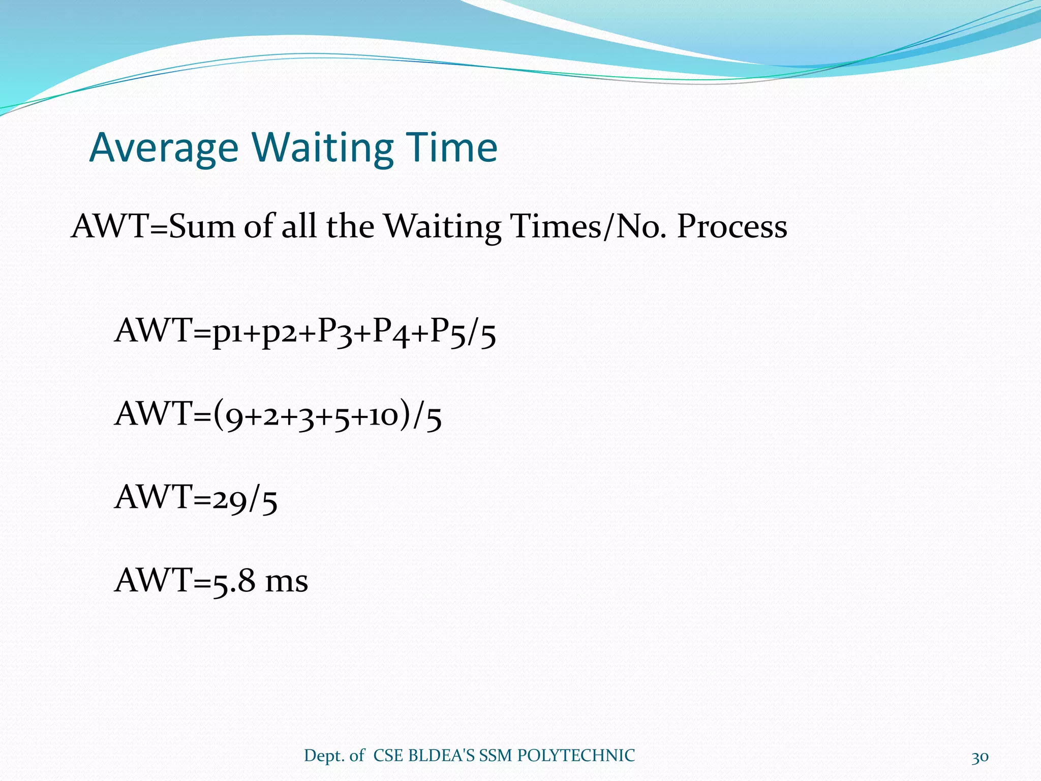
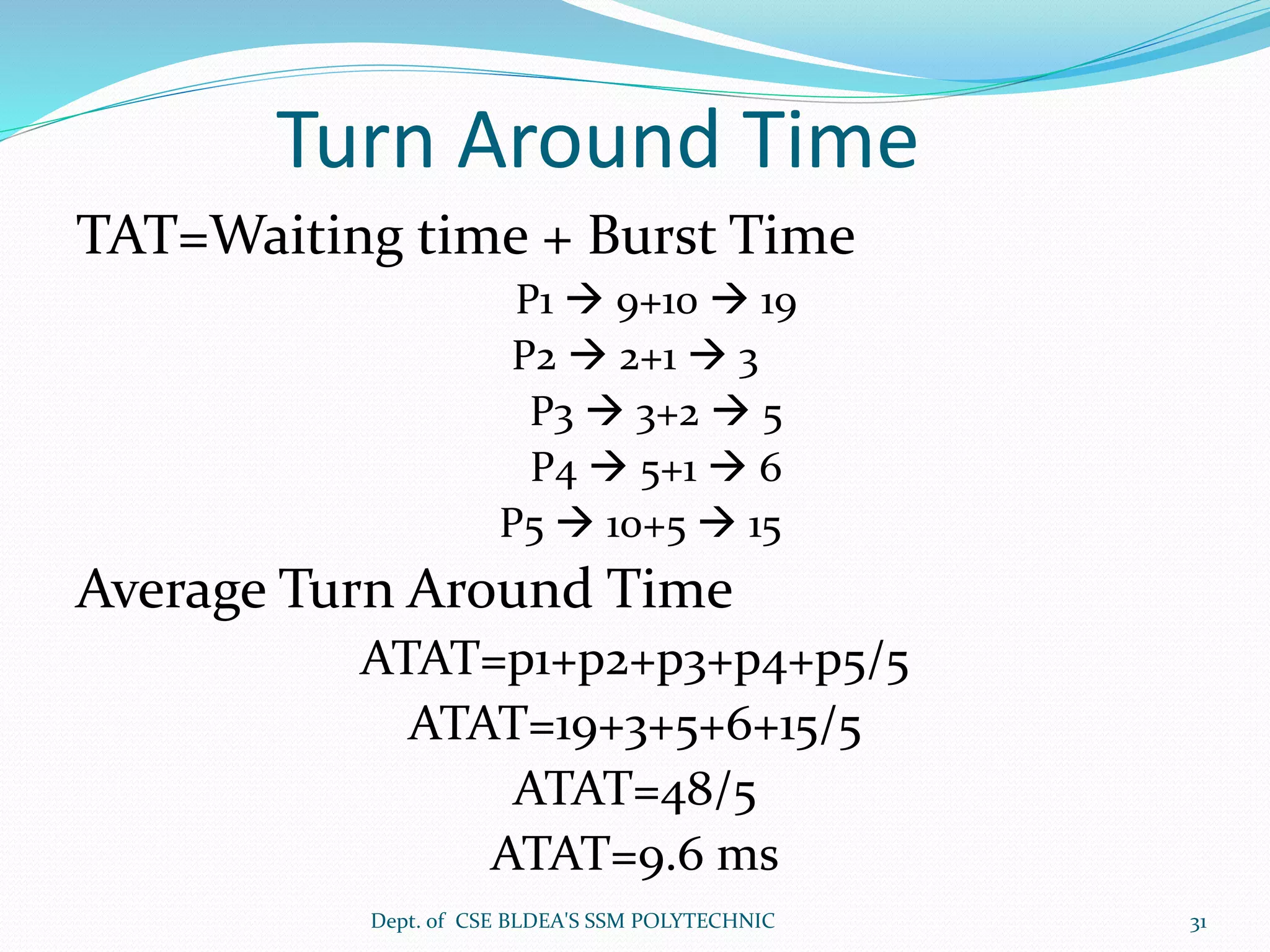
Process Management
S.R INAMDARDept. of CSE BLDEA'S SSM POLYTECHNIC 1
UNIT 2: Processes
 Process Concept
 Process Scheduling
 Operations on Processes
 Cooperating Processes
 Inter process Communication
 Process Scheduling: Basic concepts
 Scheduling criteria
 Scheduling algorithms.
Dept. of CSE BLDEA'S SSM POLYTECHNIC 2
Process Concept
 A Program in execution is called as a process.
 A process is more than a program.
 A process includes
 program counter
 stack
 data section
Dept. of CSE BLDEA'S SSM POLYTECHNIC 3
Process State Diagram
Dept. of CSE BLDEA'S SSM POLYTECHNIC 4
Process State Diagram (cont..)
 As a process executes, it changes state
 new: The process is being created.
 running: Instructions are being executed.
 waiting: The process is waiting for some event to occur.
 ready: The process is waiting to be assigned to a process.
 terminated: The process has finished execution.
Dept. of CSE BLDEA'S SSM POLYTECHNIC 5
Process Control Block (PCB)
Information associated with each process.
 Process state: ready ,new ,running etc.
 Program counter: address of next instruction to execute.
 CPU registers : PC, working registers, stack pointer.
 CPU scheduling information : scheduling order and priority.
 Memory-management information : page table/ segment table
pointers.
 Accounting information : amount CPU time used.
 I/O status information : list of I/O devices allocated to this
process and files (open).
Dept. of CSE BLDEA'S SSM POLYTECHNIC 6
Process Control Block (PCB)
Dept. of CSE BLDEA'S SSM POLYTECHNIC 7
Process Scheduling Queues
 Job queue – set of all processes in the system.
 Ready queue – set of all processes residing in main
memory, ready and waiting to execute.
 Device queues – set of processes waiting for an I/O
device.
 Process migration between the various queues.
Dept. of CSE BLDEA'S SSM POLYTECHNIC 8
Schedulers
 Long-term scheduler (or job scheduler) – selects
which processes should be brought into the ready
queue.
 Short-term scheduler (or CPU scheduler) – selects
which process should be executed next and allocates
CPU.
Dept. of CSE BLDEA'S SSM POLYTECHNIC 9
Schedulers (Cont.)
 Short-term scheduler is invoked very frequently (milliseconds) 
(must be fast).
 Long-term scheduler is invoked very infrequently (seconds, minutes)
 (may be slow).
 The long-term scheduler controls the degree of multiprogramming.
 Processes can be described as either:
 I/O-bound process – spends more time doing I/O than
computations, many short CPU bursts.
 CPU-bound process – spends more time doing computations; few
very long CPU bursts.
Dept. of CSE BLDEA'S SSM POLYTECHNIC 10
Medium Term Scheduling
Dept. of CSE BLDEA'S SSM POLYTECHNIC 11
Process Creation
 Parent process create children processes, which, in turn create
other processes, forming a tree of processes.
 Resource sharing
 Parent and children share all resources.
 Children share subset of parent’s resources.
 Parent and child share no resources.
 Execution
 Parent and children execute concurrently.
 Parent waits until children terminate.
Dept. of CSE BLDEA'S SSM POLYTECHNIC 12
Process Creation (Cont.)
 Address space
 Child duplicate of parent.
 Child has a program loaded into it.
 UNIX examples
 fork system call creates new process
 exec system call used after a fork to replace the process’
memory space with a new program.
Dept. of CSE BLDEA'S SSM POLYTECHNIC 13
Process Termination
 Process executes last statement and asks the operating system to decide
it (exit).
 Output data from child to parent (via wait).
 Process’ resources are de allocated by operating system.
 Parent may terminate execution of children processes (abort).
 Child has exceeded allocated resources.
 Task assigned to child is no longer required.
 Parent is exiting.
 Operating system does not allow child to continue if its parent
terminates.
 Cascading termination.
Dept. of CSE BLDEA'S SSM POLYTECHNIC 14
Cooperating Processes
 Independent process cannot affect or be affected by the execution
of another process.
 Cooperating process can affect or be affected by the execution of
another process
 Advantages of process cooperation
 Information sharing
 Computation speed-up
 Modularity
 Convenience
Dept. of CSE BLDEA'S SSM POLYTECHNIC 15
Interprocess Communication (IPC)
 Mechanism for processes to communicate and to
synchronize their actions.
 Message system – processes communicate with each
other without resorting to shared variables.
 IPC facility provides two operations:
 send(message) – message size fixed or variable
 receive(message)
 If P and Q wish to communicate, they need to:
 establish a communication link between them
 exchange messages via send/receive
 Implementation of communication link
 physical (e.g., shared memory, hardware bus)
 logical (e.g., logical properties)
Dept. of CSE BLDEA'S SSM POLYTECHNIC 16
Interprocess Communication (IPC)
(contd..)
Communication may take place using either
message passing or shared memory.
Dept. of CSE BLDEA'S SSM POLYTECHNIC 17
Process scheduling:Basic Concepts
 Maximum CPU utilization obtained with
multiprogramming
 CPU–I/O Burst Cycle – Process execution consists of a
cycle of CPU execution and I/O wait.
 CPU burst distribution
Dept. of CSE BLDEA'S SSM POLYTECHNIC 18
Alternating Sequence of CPU
And I/O Bursts
Dept. of CSE BLDEA'S SSM POLYTECHNIC 19
Scheduling Criteria
 CPU utilization – keep the CPU as busy as possible
 Throughput – # of processes that complete their
execution per time unit
 Turnaround time – amount of time to execute a
particular process
 Waiting time – amount of time a process has been
waiting in the ready queue
 Response time – amount of time it takes from when a
request was submitted until the first response is
produced, not output (for time-sharing environment)
Dept. of CSE BLDEA'S SSM POLYTECHNIC 20
Dept. of CSE BLDEA'S SSM POLYTECHNIC 21
PROBLEM:
Consider the following set of process with the length of the
CPU & Burst time given in millisecond.
PROCESS BURST TIME PRIORITY
P1 10 3
P2 01 1
P3 02 3
P4 01 4
P5 05 2
With Gantt chart , calculate the Average Waiting Time &
Average Turn Around Time for FCFS , SJF, Priority & RR
Scheduling. The processes are assumed to arrive in the order
p1, p2, p3, p4,p5.
Dept. of CSE BLDEA'S SSM POLYTECHNIC 22
FCFS(FIRST COME FIRST SERVE)
Gantt Chart:
P1
0 10
P2 P3 P4 P5
11 13 14 19
Waiting Time
P1  0
P2  10
P3  11
P4  13
P5  14
Average Waiting Time
AWT=Sum of all the Waiting Times/No. Process
AWT=p1+p2+P3+P4+P5/5
AWT=(0+10+11+13+14)/5
AWT=48/5
AWT=9.6 msDept. of CSE BLDEA'S SSM POLYTECHNIC 23
Turn Around Time
TAT=Waiting time + Burst Time
P1  0+10  10
P2  10+1  11
P3  11+2  13
P4  13+1  14
P5  14+5  19
Average Turn Around Time
ATAT=p1+p2+p3+p4+p5/5
ATAT=10+11+13+14+19/5
ATAT=67/5
ATAT=13.4ms
Dept. of CSE BLDEA'S SSM POLYTECHNIC 24
SJF(SHORTEST JOB FIRST)
Gantt Chart:
P2
0 1
P4 P3 P5 P1
2 4 9 19
Waiting Time
P1  9
P2  0
P3  2
P4  1
P5  4
Average Waiting Time
AWT=Sum of all the Waiting Times/No. Process
AWT=p1+p2+P3+P4+P5/5
AWT=(9+0+2+1+4)/5
AWT=16/5
AWT=3.2 msDept. of CSE BLDEA'S SSM POLYTECHNIC 25
Turn Around Time
TAT=Waiting time + Burst Time
P1  9+10  19
P2  0+1  1
P3  2+2  4
P4  1+1  2
P5  4+5  9
Average Turn Around Time
ATAT=p1+p2+p3+p4+p5/5
ATAT=19+1+4+2+9/5
ATAT=35/5
ATAT=7 ms
Dept. of CSE BLDEA'S SSM POLYTECHNIC 26
PRIORITY SCHEDULING
Gantt Chart:
P2
0 1
P5 P1 P3 P1
6 16 18 19
Waiting Time
P1  6
P2  0
P3  16
P4  18
P5  1
Average Waiting Time
AWT=Sum of all the Waiting Times/No. Process
AWT=p1+p2+P3+P4+P5/5
AWT=(6+0+16+18+1)/5
AWT=41/5
AWT=8.2 msDept. of CSE BLDEA'S SSM POLYTECHNIC 27
Turn Around Time
TAT=Waiting time + Burst Time
P1  6+10  16
P2  0+1  1
P3  16+2  18
P4  18+1  19
P5  1+5  6
Average Turn Around Time
ATAT=p1+p2+p3+p4+p5/5
ATAT=16+1+18+19+6/5
ATAT=70/5
ATAT=14 ms
Dept. of CSE BLDEA'S SSM POLYTECHNIC 28
RR(ROUND ROBIN)
Gantt Chart:
P1
0
P2 P3 P4 P1P5P1P5 P1P1P5
2 3 65 108 12 1514 1917
Waiting Time
P1  (8-2)+(12-10)+(15-14)  9
P2  2
P3  3
P4  5
P5  6+(10-8)+(14-12)  10
P1  19-10 =9
P2  3-1=2
P3  5-2=3
P4  6-1=5
P5  15-5=10
Dept. of CSE BLDEA'S SSM POLYTECHNIC 29
Average Waiting Time
AWT=Sum of all the Waiting Times/No. Process
AWT=p1+p2+P3+P4+P5/5
AWT=(9+2+3+5+10)/5
AWT=29/5
AWT=5.8 ms
Dept. of CSE BLDEA'S SSM POLYTECHNIC 30
Turn Around Time
TAT=Waiting time + Burst Time
P1  9+10  19
P2  2+1  3
P3  3+2  5
P4  5+1  6
P5  10+5  15
Average Turn Around Time
ATAT=p1+p2+p3+p4+p5/5
ATAT=19+3+5+6+15/5
ATAT=48/5
ATAT=9.6 ms
Dept. of CSE BLDEA'S SSM POLYTECHNIC 31
THANK
YOU
Dept. of CSE BLDEA'S SSM POLYTECHNIC 32

Unit 2 process Management

  • 1.
    Process Management S.R INAMDARDept.of CSE BLDEA'S SSM POLYTECHNIC 1
  • 2.
    UNIT 2: Processes Process Concept  Process Scheduling  Operations on Processes  Cooperating Processes  Inter process Communication  Process Scheduling: Basic concepts  Scheduling criteria  Scheduling algorithms. Dept. of CSE BLDEA'S SSM POLYTECHNIC 2
  • 3.
    Process Concept  AProgram in execution is called as a process.  A process is more than a program.  A process includes  program counter  stack  data section Dept. of CSE BLDEA'S SSM POLYTECHNIC 3
  • 4.
    Process State Diagram Dept.of CSE BLDEA'S SSM POLYTECHNIC 4
  • 5.
    Process State Diagram(cont..)  As a process executes, it changes state  new: The process is being created.  running: Instructions are being executed.  waiting: The process is waiting for some event to occur.  ready: The process is waiting to be assigned to a process.  terminated: The process has finished execution. Dept. of CSE BLDEA'S SSM POLYTECHNIC 5
  • 6.
    Process Control Block(PCB) Information associated with each process.  Process state: ready ,new ,running etc.  Program counter: address of next instruction to execute.  CPU registers : PC, working registers, stack pointer.  CPU scheduling information : scheduling order and priority.  Memory-management information : page table/ segment table pointers.  Accounting information : amount CPU time used.  I/O status information : list of I/O devices allocated to this process and files (open). Dept. of CSE BLDEA'S SSM POLYTECHNIC 6
  • 7.
    Process Control Block(PCB) Dept. of CSE BLDEA'S SSM POLYTECHNIC 7
  • 8.
    Process Scheduling Queues Job queue – set of all processes in the system.  Ready queue – set of all processes residing in main memory, ready and waiting to execute.  Device queues – set of processes waiting for an I/O device.  Process migration between the various queues. Dept. of CSE BLDEA'S SSM POLYTECHNIC 8
  • 9.
    Schedulers  Long-term scheduler(or job scheduler) – selects which processes should be brought into the ready queue.  Short-term scheduler (or CPU scheduler) – selects which process should be executed next and allocates CPU. Dept. of CSE BLDEA'S SSM POLYTECHNIC 9
  • 10.
    Schedulers (Cont.)  Short-termscheduler is invoked very frequently (milliseconds)  (must be fast).  Long-term scheduler is invoked very infrequently (seconds, minutes)  (may be slow).  The long-term scheduler controls the degree of multiprogramming.  Processes can be described as either:  I/O-bound process – spends more time doing I/O than computations, many short CPU bursts.  CPU-bound process – spends more time doing computations; few very long CPU bursts. Dept. of CSE BLDEA'S SSM POLYTECHNIC 10
  • 11.
    Medium Term Scheduling Dept.of CSE BLDEA'S SSM POLYTECHNIC 11
  • 12.
    Process Creation  Parentprocess create children processes, which, in turn create other processes, forming a tree of processes.  Resource sharing  Parent and children share all resources.  Children share subset of parent’s resources.  Parent and child share no resources.  Execution  Parent and children execute concurrently.  Parent waits until children terminate. Dept. of CSE BLDEA'S SSM POLYTECHNIC 12
  • 13.
    Process Creation (Cont.) Address space  Child duplicate of parent.  Child has a program loaded into it.  UNIX examples  fork system call creates new process  exec system call used after a fork to replace the process’ memory space with a new program. Dept. of CSE BLDEA'S SSM POLYTECHNIC 13
  • 14.
    Process Termination  Processexecutes last statement and asks the operating system to decide it (exit).  Output data from child to parent (via wait).  Process’ resources are de allocated by operating system.  Parent may terminate execution of children processes (abort).  Child has exceeded allocated resources.  Task assigned to child is no longer required.  Parent is exiting.  Operating system does not allow child to continue if its parent terminates.  Cascading termination. Dept. of CSE BLDEA'S SSM POLYTECHNIC 14
  • 15.
    Cooperating Processes  Independentprocess cannot affect or be affected by the execution of another process.  Cooperating process can affect or be affected by the execution of another process  Advantages of process cooperation  Information sharing  Computation speed-up  Modularity  Convenience Dept. of CSE BLDEA'S SSM POLYTECHNIC 15
  • 16.
    Interprocess Communication (IPC) Mechanism for processes to communicate and to synchronize their actions.  Message system – processes communicate with each other without resorting to shared variables.  IPC facility provides two operations:  send(message) – message size fixed or variable  receive(message)  If P and Q wish to communicate, they need to:  establish a communication link between them  exchange messages via send/receive  Implementation of communication link  physical (e.g., shared memory, hardware bus)  logical (e.g., logical properties) Dept. of CSE BLDEA'S SSM POLYTECHNIC 16
  • 17.
    Interprocess Communication (IPC) (contd..) Communicationmay take place using either message passing or shared memory. Dept. of CSE BLDEA'S SSM POLYTECHNIC 17
  • 18.
    Process scheduling:Basic Concepts Maximum CPU utilization obtained with multiprogramming  CPU–I/O Burst Cycle – Process execution consists of a cycle of CPU execution and I/O wait.  CPU burst distribution Dept. of CSE BLDEA'S SSM POLYTECHNIC 18
  • 19.
    Alternating Sequence ofCPU And I/O Bursts Dept. of CSE BLDEA'S SSM POLYTECHNIC 19
  • 20.
    Scheduling Criteria  CPUutilization – keep the CPU as busy as possible  Throughput – # of processes that complete their execution per time unit  Turnaround time – amount of time to execute a particular process  Waiting time – amount of time a process has been waiting in the ready queue  Response time – amount of time it takes from when a request was submitted until the first response is produced, not output (for time-sharing environment) Dept. of CSE BLDEA'S SSM POLYTECHNIC 20
  • 21.
    Dept. of CSEBLDEA'S SSM POLYTECHNIC 21
  • 22.
    PROBLEM: Consider the followingset of process with the length of the CPU & Burst time given in millisecond. PROCESS BURST TIME PRIORITY P1 10 3 P2 01 1 P3 02 3 P4 01 4 P5 05 2 With Gantt chart , calculate the Average Waiting Time & Average Turn Around Time for FCFS , SJF, Priority & RR Scheduling. The processes are assumed to arrive in the order p1, p2, p3, p4,p5. Dept. of CSE BLDEA'S SSM POLYTECHNIC 22
  • 23.
    FCFS(FIRST COME FIRSTSERVE) Gantt Chart: P1 0 10 P2 P3 P4 P5 11 13 14 19 Waiting Time P1  0 P2  10 P3  11 P4  13 P5  14 Average Waiting Time AWT=Sum of all the Waiting Times/No. Process AWT=p1+p2+P3+P4+P5/5 AWT=(0+10+11+13+14)/5 AWT=48/5 AWT=9.6 msDept. of CSE BLDEA'S SSM POLYTECHNIC 23
  • 24.
    Turn Around Time TAT=Waitingtime + Burst Time P1  0+10  10 P2  10+1  11 P3  11+2  13 P4  13+1  14 P5  14+5  19 Average Turn Around Time ATAT=p1+p2+p3+p4+p5/5 ATAT=10+11+13+14+19/5 ATAT=67/5 ATAT=13.4ms Dept. of CSE BLDEA'S SSM POLYTECHNIC 24
  • 25.
    SJF(SHORTEST JOB FIRST) GanttChart: P2 0 1 P4 P3 P5 P1 2 4 9 19 Waiting Time P1  9 P2  0 P3  2 P4  1 P5  4 Average Waiting Time AWT=Sum of all the Waiting Times/No. Process AWT=p1+p2+P3+P4+P5/5 AWT=(9+0+2+1+4)/5 AWT=16/5 AWT=3.2 msDept. of CSE BLDEA'S SSM POLYTECHNIC 25
  • 26.
    Turn Around Time TAT=Waitingtime + Burst Time P1  9+10  19 P2  0+1  1 P3  2+2  4 P4  1+1  2 P5  4+5  9 Average Turn Around Time ATAT=p1+p2+p3+p4+p5/5 ATAT=19+1+4+2+9/5 ATAT=35/5 ATAT=7 ms Dept. of CSE BLDEA'S SSM POLYTECHNIC 26
  • 27.
    PRIORITY SCHEDULING Gantt Chart: P2 01 P5 P1 P3 P1 6 16 18 19 Waiting Time P1  6 P2  0 P3  16 P4  18 P5  1 Average Waiting Time AWT=Sum of all the Waiting Times/No. Process AWT=p1+p2+P3+P4+P5/5 AWT=(6+0+16+18+1)/5 AWT=41/5 AWT=8.2 msDept. of CSE BLDEA'S SSM POLYTECHNIC 27
  • 28.
    Turn Around Time TAT=Waitingtime + Burst Time P1  6+10  16 P2  0+1  1 P3  16+2  18 P4  18+1  19 P5  1+5  6 Average Turn Around Time ATAT=p1+p2+p3+p4+p5/5 ATAT=16+1+18+19+6/5 ATAT=70/5 ATAT=14 ms Dept. of CSE BLDEA'S SSM POLYTECHNIC 28
  • 29.
    RR(ROUND ROBIN) Gantt Chart: P1 0 P2P3 P4 P1P5P1P5 P1P1P5 2 3 65 108 12 1514 1917 Waiting Time P1  (8-2)+(12-10)+(15-14)  9 P2  2 P3  3 P4  5 P5  6+(10-8)+(14-12)  10 P1  19-10 =9 P2  3-1=2 P3  5-2=3 P4  6-1=5 P5  15-5=10 Dept. of CSE BLDEA'S SSM POLYTECHNIC 29
  • 30.
    Average Waiting Time AWT=Sumof all the Waiting Times/No. Process AWT=p1+p2+P3+P4+P5/5 AWT=(9+2+3+5+10)/5 AWT=29/5 AWT=5.8 ms Dept. of CSE BLDEA'S SSM POLYTECHNIC 30
  • 31.
    Turn Around Time TAT=Waitingtime + Burst Time P1  9+10  19 P2  2+1  3 P3  3+2  5 P4  5+1  6 P5  10+5  15 Average Turn Around Time ATAT=p1+p2+p3+p4+p5/5 ATAT=19+3+5+6+15/5 ATAT=48/5 ATAT=9.6 ms Dept. of CSE BLDEA'S SSM POLYTECHNIC 31
  • 32.
    THANK YOU Dept. of CSEBLDEA'S SSM POLYTECHNIC 32