Downloaded 40 times
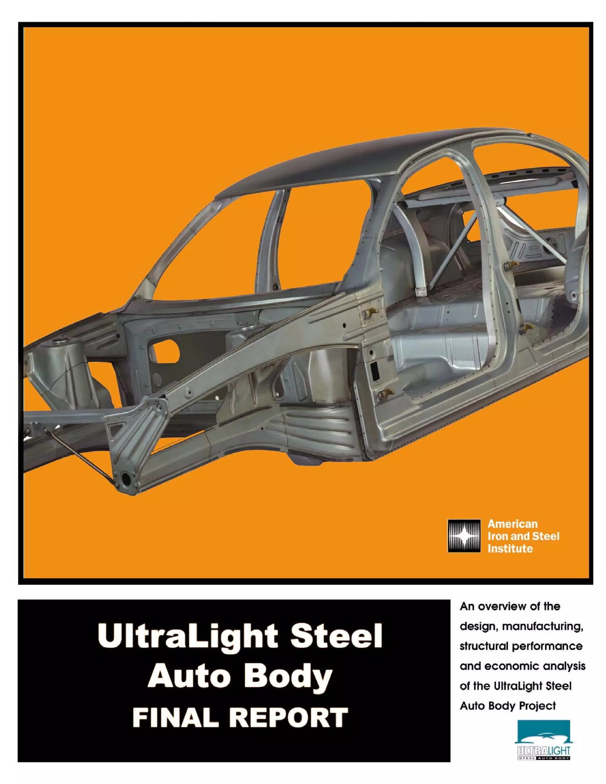


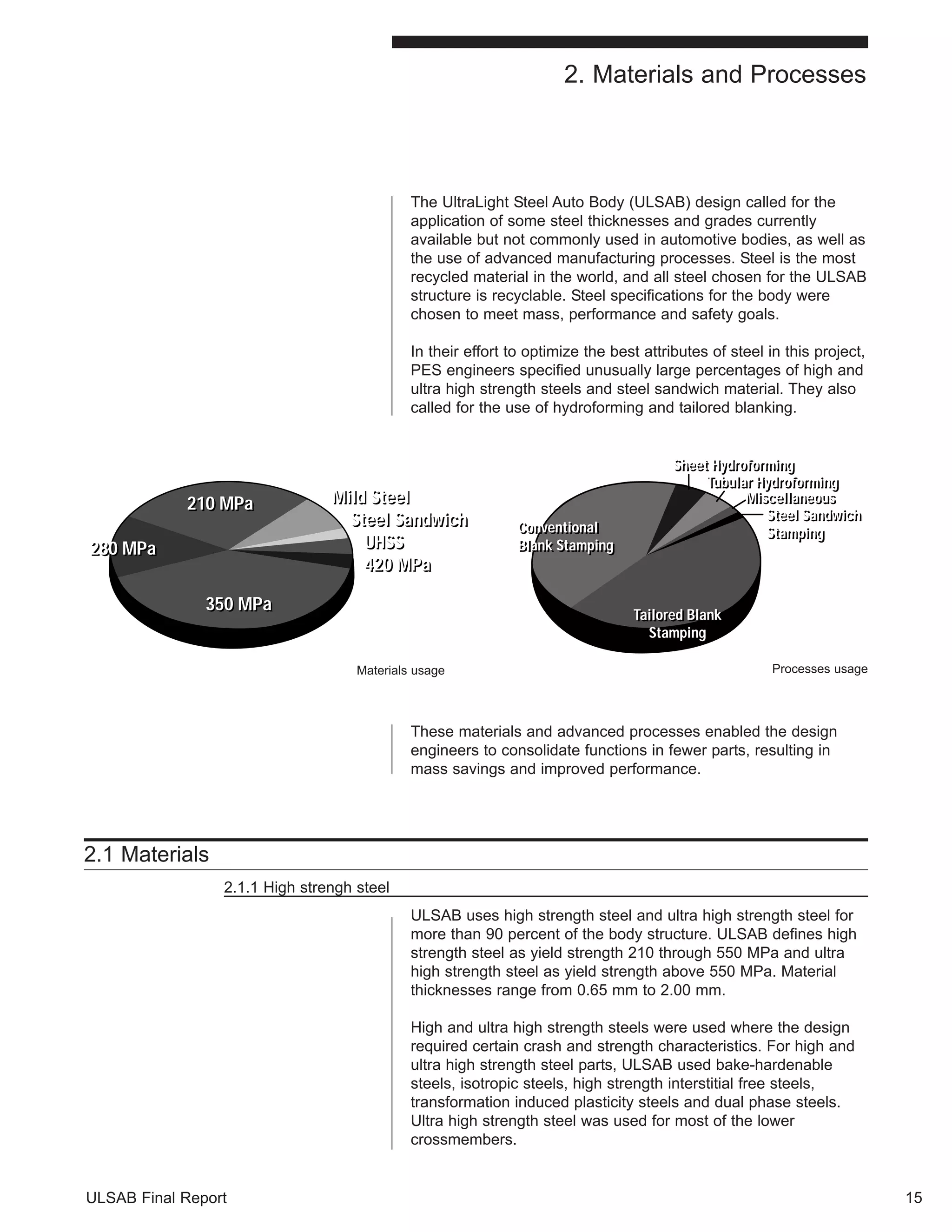

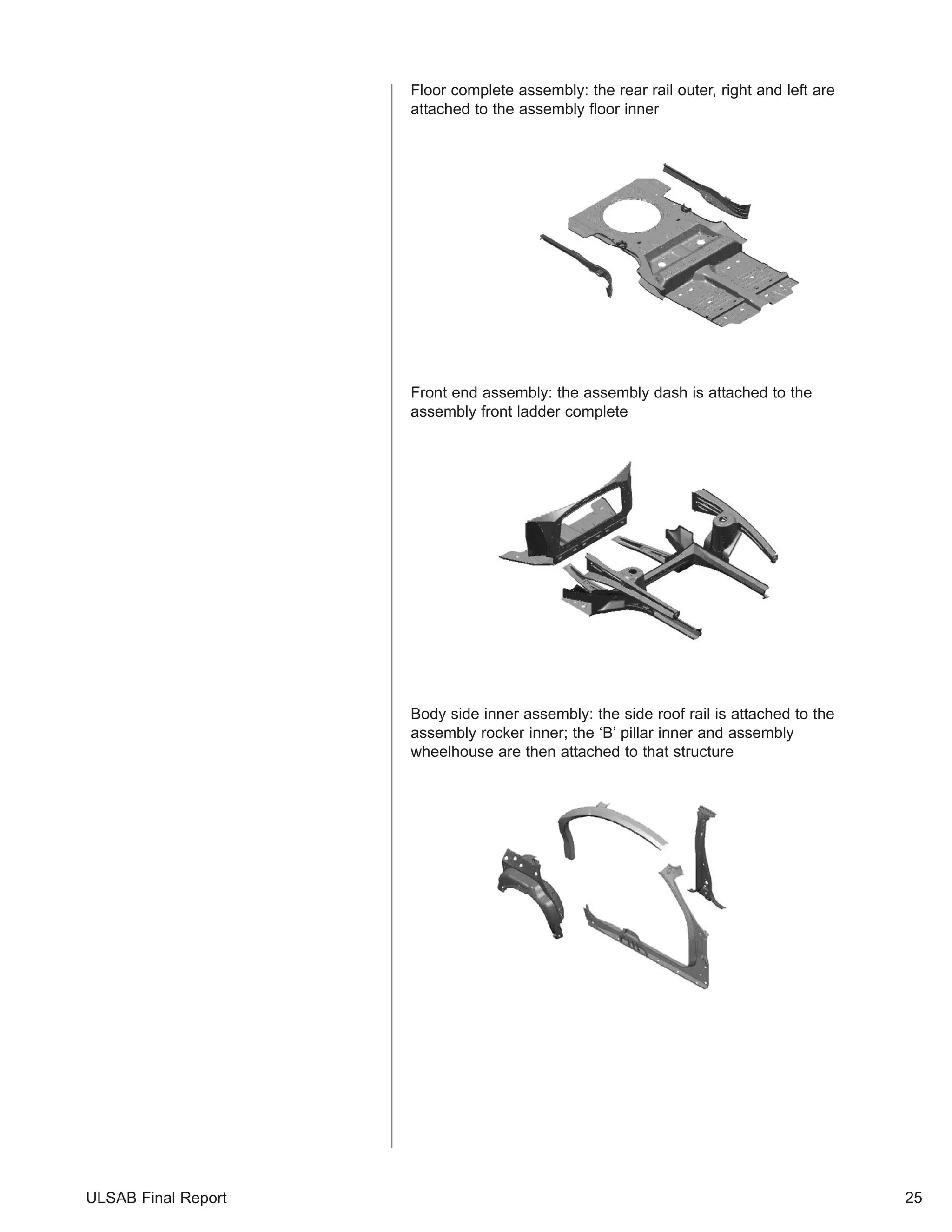
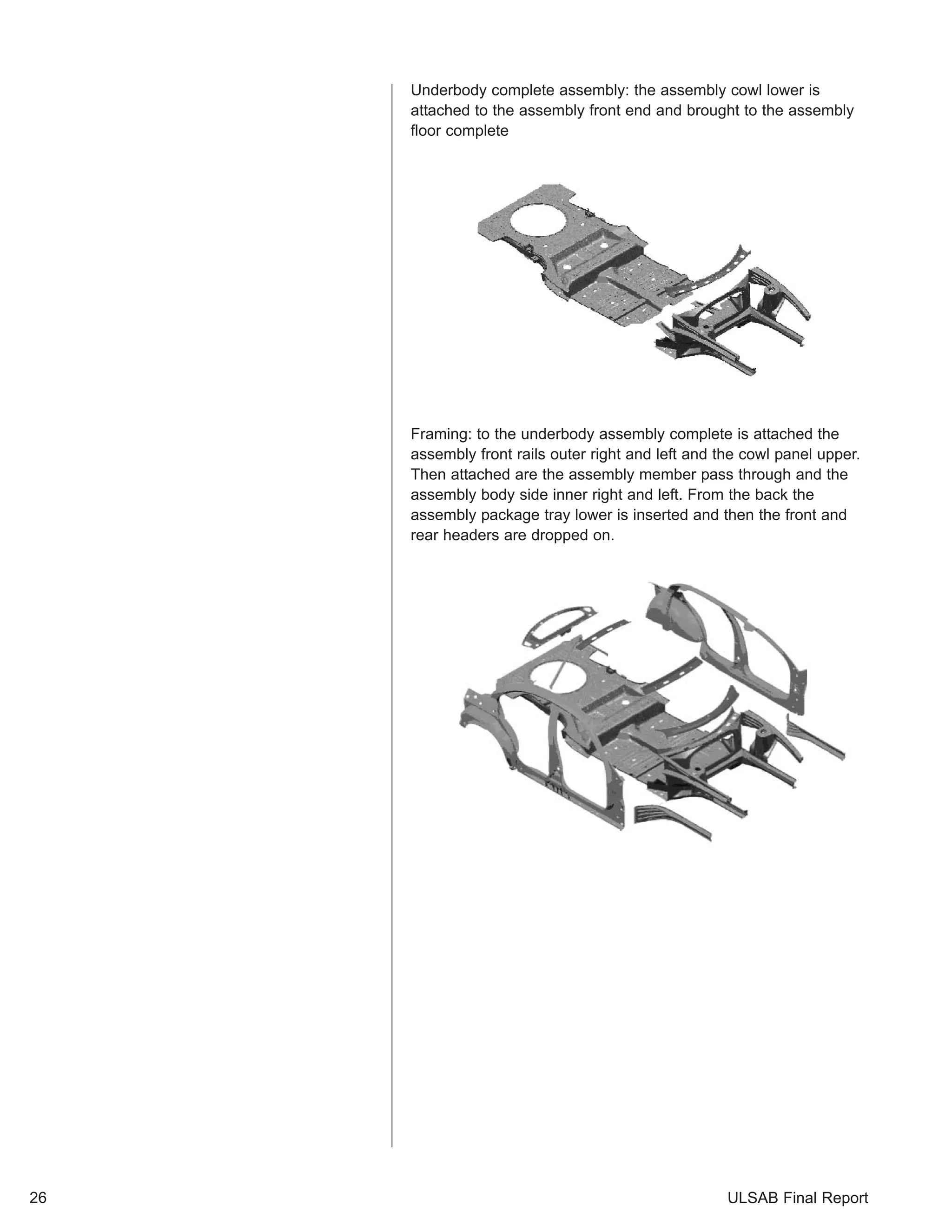
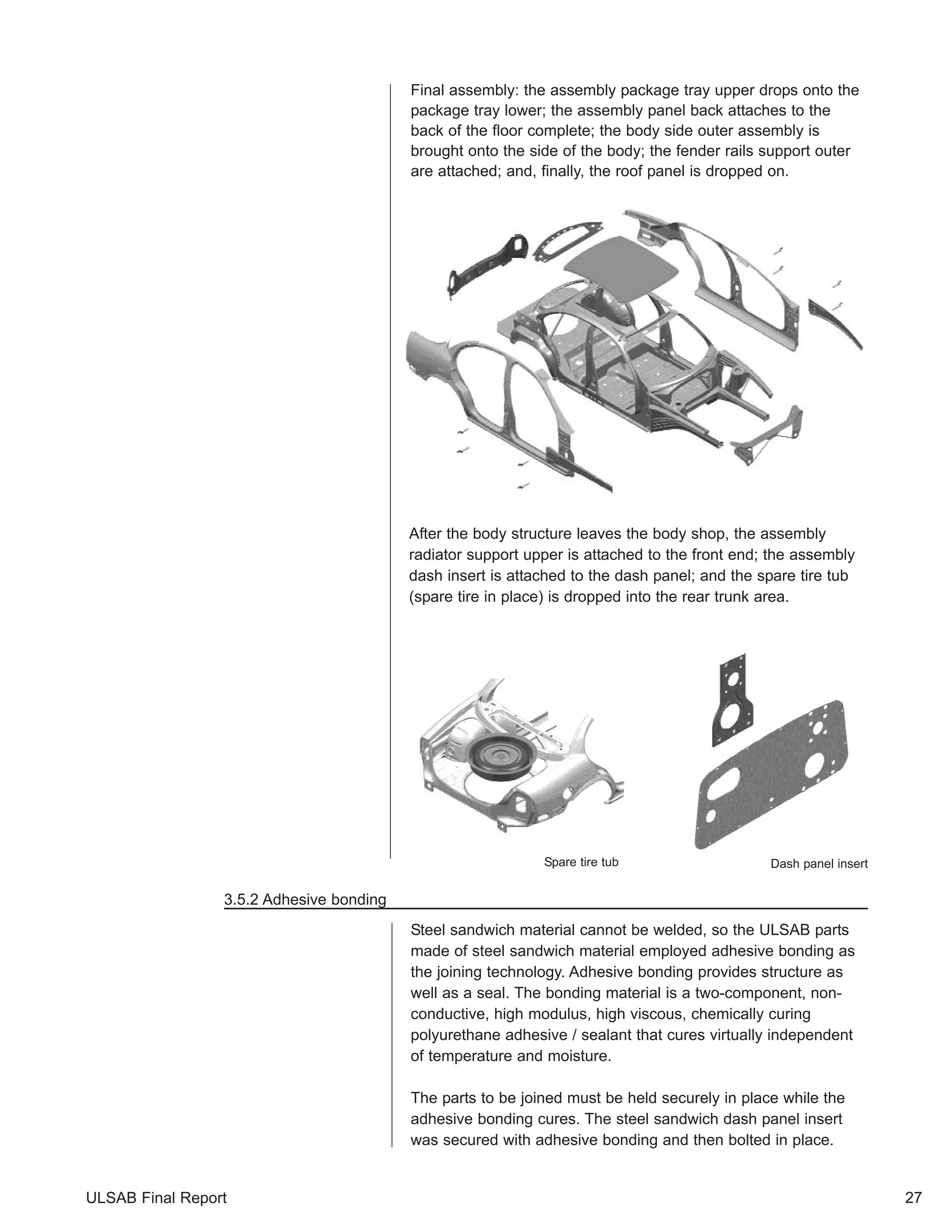
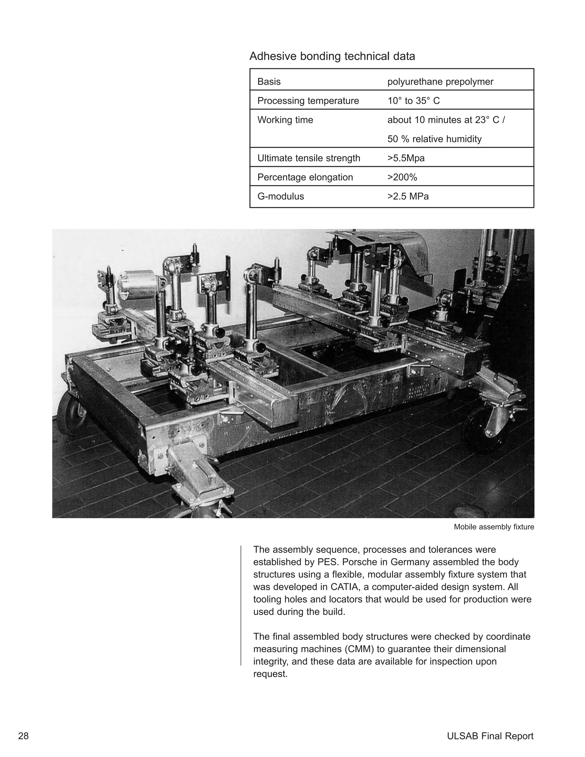
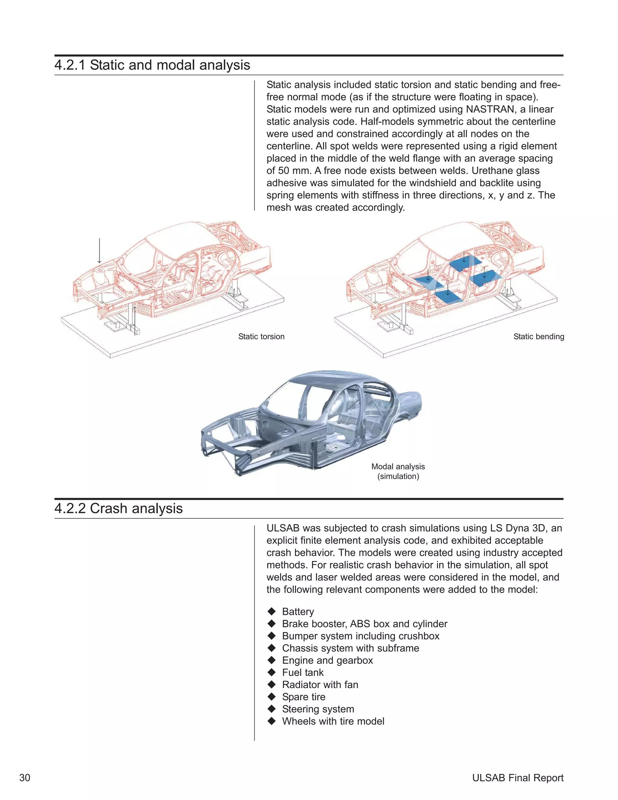
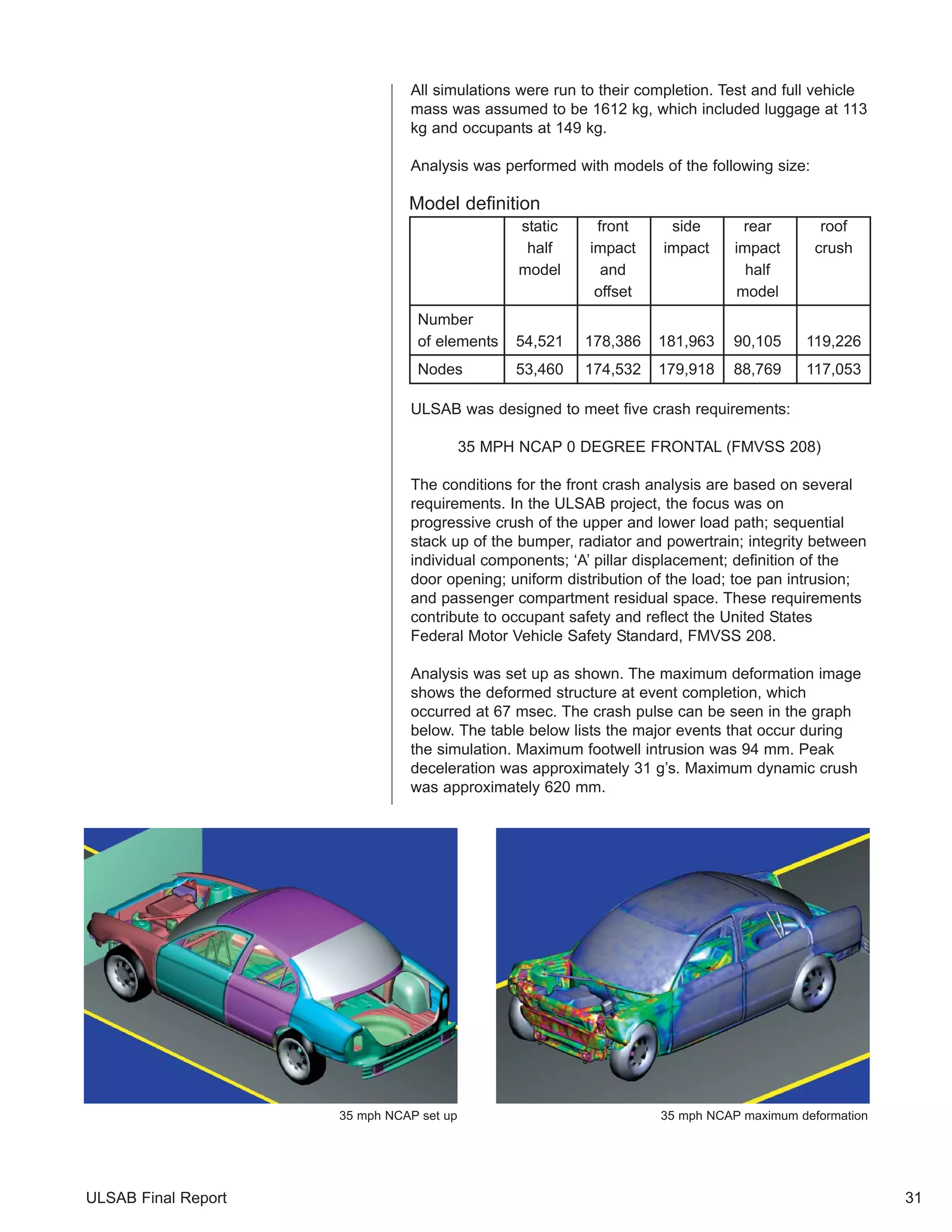
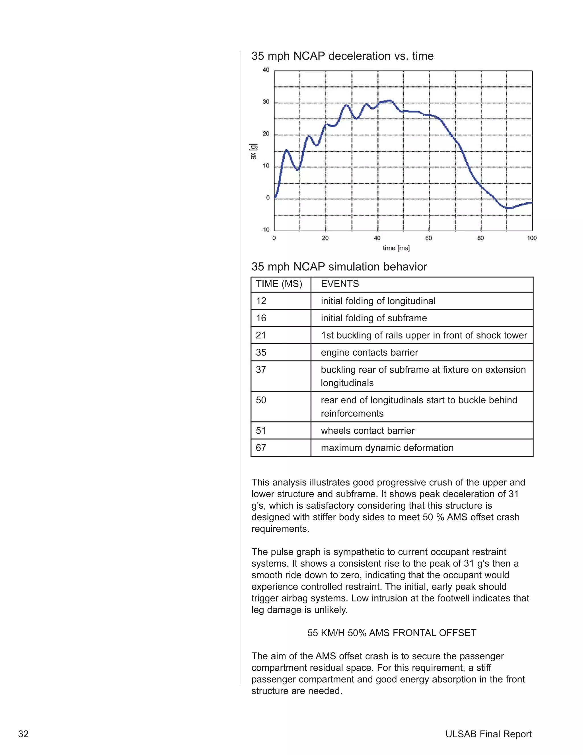
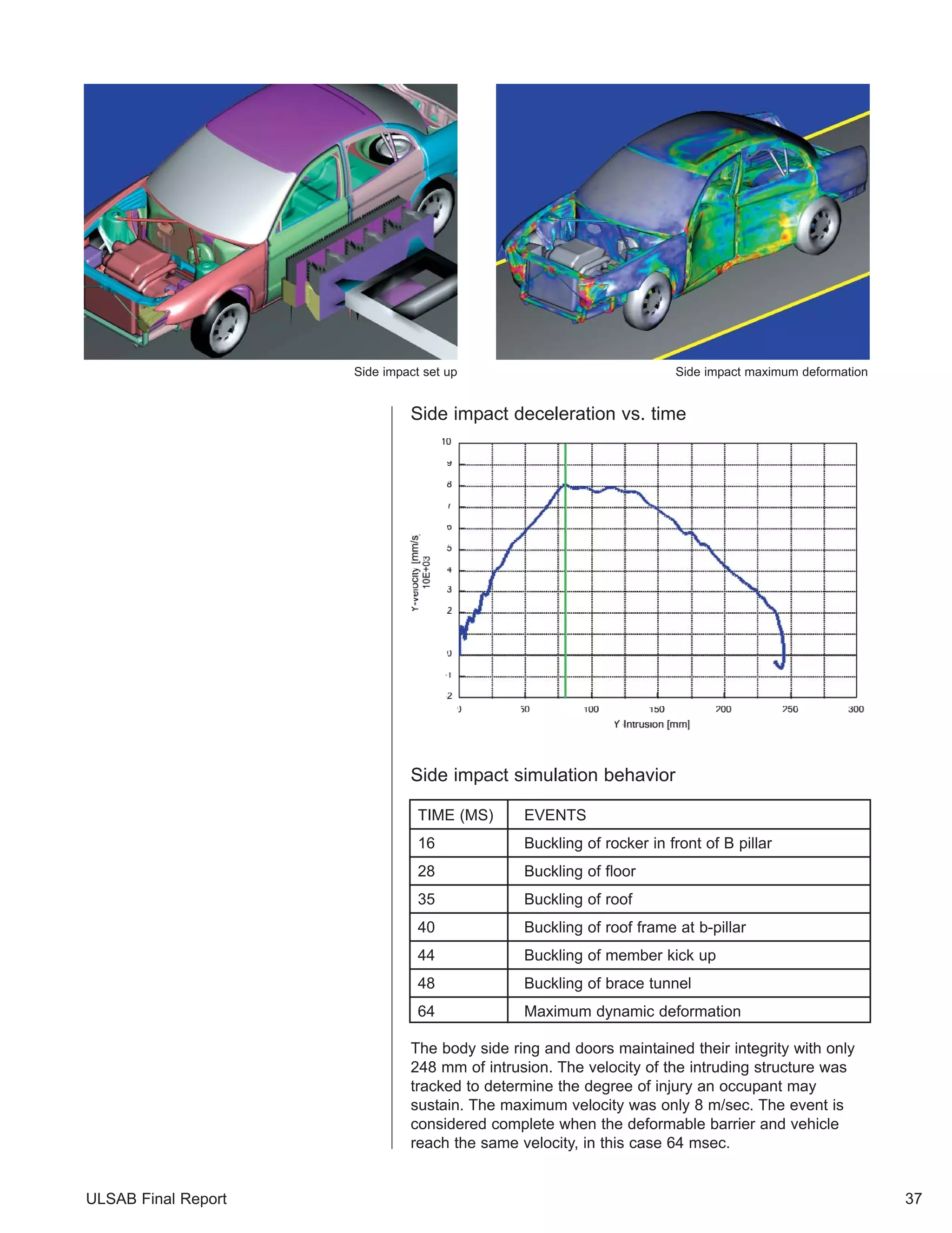
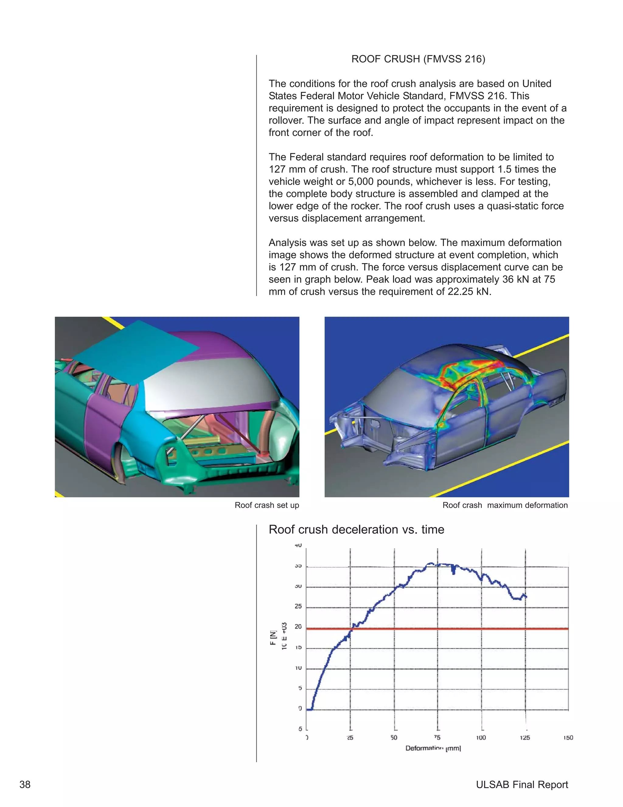

The UltraLight Steel Auto Body (ULSAB) Consortium designed and validated a lightweight steel auto body structure that meets increased performance targets while remaining affordable to produce. The final report details the design process, including benchmarking existing vehicles, establishing packaging and performance goals, and selecting a unibody design with hydroformed parts. Physical testing showed the ULSAB structure exceeds benchmarks for torsional and bending rigidity by 80% and 52% respectively. Computational analysis also indicated it meets crash standards. At 203kg, the ULSAB structure weighs up to 36% less than benchmarks and economic analysis found it costs similar or less to produce than conventional designs.