Quality defects in TMT Bars, Possible causes and Potential Solutions.
biw-.pdf
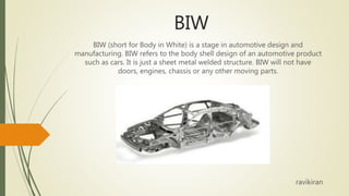
1. BIW
BIW (short for Body in White) is a stage in automotive design and
manufacturing. BIW refers to the body shell design of an automotive product
such as cars. It is just a sheet metal welded structure. BIW will not have
doors, engines, chassis or any other moving parts.
ravikiran
3. BIW Types:
There are mainly two types
Frame Mounted Body Structure
Monocoqe Body Structure
Frame Mounted Body Structure
• Its also called as Body on Frame construction.
• In this type Body is mounted on the Chassis/Frame.
• Powertrains and suspension are mounted on chassis.
• Used in utility vehicles, trucks, buses.
4. Monocoqe Body Structure
• It also called as Chassis in built in Body.
• Chassis/Frame is inbuilt with BIW itself and there is no separate chassis.
• Powertrains and suspension are directly mounted to BIW.
5. BIW Components:
A,B,C,D Pillars
Dashboard mounting panel
Windscreen & Rear Window rail
Cant rail
Roof structure
Side Sill
Quarter panel or window
cross member
Front & rear Valance
Scuttle
Firewall
Floor, seat & Boot pan
Front & rear Spring tower
Central Console
Front & Rear Wheel arch
Toe Board
Heel Board
6. A,B,C,D Pillars
• A pillars is the front most support of the roof.
• B pillars is the second support of the roof.
• C/D are last support of the roof.
Dashboard mounting panel
• A dashboard (also called dash, instrument panel (IP), or fascia) is a control panel located directly ahead of a vehicle's
driver, displaying instrumentation and controls for the vehicle's operation.
Windscreen & Rear Window rail
• Windshields protect the vehicle's occupants from wind and flying debris such as dust, insects, and rocks, and provide
an aerodynamically formed window towards the front.
Cant rail
• In the construction of the body-side. It is canted in that the top is angled to match the roof profile.
Roof structure
• Structure above the windshields.
Side Sill
• A side sill longitudinally extending at each of laterally opposite sides of a lower portion of a vehicle body is provided
with a substantially uniform box-like cross-section which is defined by a top and a bottom wall and a right and a left
side wall.
7. Quarter panel or window
• A quarter panel is the body panel (exterior surface) of an automobile between a rear door (or only door on each
side for two-door models)and the trunk (boot) and typically wraps around the wheel well. The similar front
section between the door and the hood (bonnet), is called a fender, but is sometimes incorrectly also referred to
as a quarter panel. Quarter panels are typically made of sheet metal, but are sometimes made
of fiberglass, carbon fiber, or fiber-reinforced plastic.
cross member
• A cross member is a structural section that is transverse to the main structure. The term typically refers to a
component, usually of steel, usually boxed, that is bolted across the underside of a monocoque/ unibodymotor
vehicle, to support the internal combustion engine and / or transmission. For the suspension of any car to
operate as it should, for proper handling, and to keep the body panels in alignment, the frame has to be strong
enough to cope with the loads applied to it. It must not deflect, and it has to have enough torsional strength to
resist twisting.
Front & rear Valance
• Front valance is the sheet metal panel below the front bumper attached to the fenders. Rear valance is the metal
panel that runs under the rear bumper between the quarter panels.
Scuttle
• A scuttle drain is used to divert any water which falls on your car windscreen to the ground, without coming into
contact with your engine.
Firewall
• The firewall is the part of the automobile body that separates the engine compartment from the passenger
compartment
8. Floor, seat & Boot pan
• The floor pan is a large sheet metal stamping that often incorporates several smaller welded stampings to form the
floor of a large vehicle and the position of its external and structural panels. In the case of monocoque designs, the
most important metal part establishing the chassis, body, and thus the car’s size. It servethe floorplan is s as the
foundation of most of the structural and mechanical components of a unibody automobile to which
the powertrain, suspension system, and other parts are attached.
• Boot pan is the rear hallow section of the structure.
Front & rear Spring tower
• It is also called as shock towers.
• A shock tower includes first and second portions for attaching a suspension damper and a control arm to a
vehicular body.
Central console
• It refers to the control-bearing surfaces in the center of the front of the vehicle interior. The term is applied to the
area beginning in the dashboard and continuing beneath it, and often merging with the transmission tunnel which
runs between the front driver's and passenger's seats of many vehicles.
Front & Rear Wheel arch
• A break between the planes and wheels and planes are accommodate with the guards.
Toe Board
• The front vertical panel that provides support for the pedals and for the front passenger's feet, usually inclined
towards the front and spot-welded to the floorboard at its bottom end and to the bulkhead at its upper end.
Heel Board
• The vertical transverse sheet metal panel running across the width of the car interior at the front edge of the rear
seat well; this panel links the rear seat well to the floor pan and provides rigidity for both panels. Also called heel
plate.
9. A pillar
B pillar
C pillar
Dash Board mounting plane
Wind Screen & rear window Roof structure
Side Sills
Quarter planes
and windows
Cross Members
Front & rear Valance
scuttle
Firewall
Floor, Seat and boot pan
Spring
tower
Centre Console
Front & rear wheel arch
Cant
rail
Toe Board
Heel
Board
Ravikran ,kumarkarkiran@gmail.com
10. BIW Design Consideration
Aspects of Aerodynamic
BIW Design Challenges
Concept design process
Sheet Metal Design
Design For Safety
11. Aspects of Aerodynamic
It can be defined as the science of air in motion
Importance of aerodynamic:
• Better fuel economy
• Improved road holding and stability for a vehicle
• Reduction in wind noise level
• Greater vehicle performance
Aerodynamic drag:
Profile drag:
• Contributes about 57% of the aerodynamic drag.
• Cd = D / 0.5 ρAV2
o D-aerodynamic drag force measured in wind tunnel
o ρ- density of air
o A- frontal cross section area of the body
o V- vehicle speed in km/hr
Lift induced drag:
• Contributes about 8% of total aerodynamic drag caused by vortices formed at side and downwind
Friction drag:
• Makes 10% of the aerodynamics drag
Interference drag:
• Contributes about 15% of the aerodynamics drag caused by projection mirrors, badges, handles, axles
Cooling and ventilation drag:
• Contributes about 10% of the aerodynamics drag, caused by ducting and radiators
12. BIW Design Challenges
Light weight construction
• Enabling use of light metals and composite materials results in improved fuel efficiency
• Vehicle body determines the price of vehicle both directly and indirectly. Body represents 50 to 70 % of the
total cost of the vehicle directly, indirectly the life of the vehicle can influence the price
Cost efficient design
• Reduced investment and operating costs
• Increased efficiency and cost reduction
Manufacturing process
• Minimize operations steps for final component
• Reduce material wastage
• Process flexibility with all possible variants
• Selection and adoption of new manufacturing technologies for simpler and effective operations
Right product at right time
• Attaining the right concept within shortest time to reach to customer with new innovative ideas
• Time taken to complete the overall design of a new model of a car is determined by the time taken to
design the bodywork
Engine and chassis units are easily replaceable, but serious damage to the body means an end to
vehicles life.
13. Concept design process
Product proposal & planning:
• Team of marketing evaluates product need & feasibility of product in market and finalizes product
proposal document
Product concept definition
• Requirements consideration of customer, legislative, organization
Business case
• Target market, manufacturing, costing strategically considered for business case preparation
Preliminary design concept
• Engineering converts customer, legislative, organization requirements into technical features.
Feasibility drawing
• Drawing release for feasibility study
Prototype build
• Preliminary concept evaluation, feasibility & testing
Production drawings
• Drawings released for tooling part development
Start of production
14. Sheet Metal Design
While designing components top priority is for function and second is for cost effective manufacturing process
selection
Keeping part simple
Lesser material yield
Consideration of minimum manufacturing stages
OBJECTIVES OF SHEET METAL DESIGN
• Function
o Most low stress (and many high stress) components requiring moderate stiffness can be created from sheet
metal. Sheet metal is particularly effective for parts that function as containers and structures but can effectively
be used for mounting brackets as well.
• Attachment method
o Sheet metal parts are typically joined by welding, riveting or via fasteners.
DESIGN TIPS
Shape: Use simple shapes such as straight cuts, bends, and punched holes. Whenever possible, avoid internal
cuts, curved cuts, and close-fit holes
Simple: Complex sheet metal parts are difficult to manufacture using tooling available. Typically, complex sheet
metal parts can be broken down into multiple simple parts
Material specification: Choose a optimum material and thickness
Tolerances: In modern industry parts are made using high precision CNC lasers and bending equipment.
However, sheet metal features are generally cut by aligning the layout lines by eye, so design sheet metal parts
to have large feature tolerances.
Order of operations: The order of forming operations is important for sheetmetal parts. Holes and cuts must be
created prior to bending. The bending sequence can typically be performed in only one or two ways. Be familiar
with the available tooling and processes and do not design parts that cannot be fabricated using the available
tooling in lab.
15. Design For Safety
Front crumple zone
Strong central passenger module
Rear crumple zone
The front crumple zone is designed to crush sequentially through its stage system to
maximize energy absorption.
The power train is also designed to detach from the car on heavy impact, allowing the
body structure to dissipate energy.
strong A and B pillars.
16. BIW Materials
Nowadays automobile sector is driven by light weighting key to next generation product development
using cost-effective alternative material like aluminium, composite materials in high end cars due to their
several advantages. It will become popular in low end vehicles as well in coming years.
BIW accounts @ 50% weight of vehicle and having a scope to reduce the weight by means of alternative
materials.
Steel is always favored by automobile industries due to its simplicity in fabrication, but in last several years
fuel prices are rising and recycling regulations are coming into force therefore it becomes need to reduce
weig.ht of vehicle.
Materials used in BIW are listed as below
• Aluminum – VH Architecture, bonnet and roof
• Steel – Body Sides
• Composites – Wings, tailgate and sills
• CFRP (Carbon Fiber reinforced plastic)
• ULSAC (Ultra Light Steel Auto Covers)
• ULSAS (Ultra Light Steel Auto Suspension)
17.
18. BIW Cae Analysis
Different load conditions are considered for BIW, chassis, engine mount, axles and steering
Inertia Relief(Calculate stress / strain for BIW)
• Used for analyzing the unconstrained structures
• Stress analysis on a free structure that is accelerating
• Applied forces and torques are balanced by inertial forces induced by an acceleration field
GRAVITY ANALYSIS (for Body, engine)
STATIC (Displacement / stresses (Linear & Non Linear) for monocoque chassis)
• Used to determine displacements, stresses under static loading conditions. Both linear and nonlinear static analyses. Non-
linearity can include plasticity, stress stiffening, large deflection, large strain, hyper elasticity, contact surfaces, and creep.
MODAL (Calculate Natural freq. and mode shapes of structure)
• Study of the dynamic properties of structures under vibrational excitation.(Calculate the natural frequencies and mode shapes of
a structure)
• It uses the mass and stiffness of a structure to find the various periods at which it will naturally resonate
BUCKLING (Buckling load and shape of monocoque chassis):
• Used to calculate buckling loads and determine buckling mode shape. Both linear buckling and nonlinear are possible.
HARMONIC (Fatigue / cycle / dynamic analysis of engine mount, axle, steering)
• Used to determine the response of a structure to harmonically time varying loads . A harmonic load is a cyclic load such as the
composite wave
TRANSIENT (Fatigue / cycle / dynamic analysis of engine mount, axle, steering)
• Used to determine the response of a structure to arbitrarily time varying loads. All nonlinearities mentioned under static analysis
above are allowed
19. BIW Assembly
DESIGN CONSIDERATIONS FOR SPOT WELDING:
Thickness: Parts to be welded should be equal or the ratio of thicknesses should be less than 3:1.
Minimum weld spacing = 10 x Stock
Center of weld to edge distance = 2 x weld diameter, minimum
Weld to form distance = Bend Radius + 1 weld diameter, minimum
Used for: Normally up to 3 mm (0.125 in) thickness, although parts up to 1/4 in. (6 mm) thick have
been successfully spot welded.
Spot-weld diameters: Range from 3 mm to 12.5 mm in diameter
Positioning and Accessibility: Multiple bends impose access restrictions, and special fixtures may have
to be designed to handle the parts, if access is not a problem.
Cosmetics: limit spot welding on appearance or cosmetic surfaces. grinding, or filling and grinding, is
often required and can double the cost of the welding operation
Plating Spot Welded Parts: Plating drainage must be considered because sometimes electroplating
solution gets trapped in assembly residues causes corrosion / manual removal
Positive Location of Work pieces: The mating parts can be self-jigged for easy location prior to
welding. It can be achieved by half sheared or extruded cylindrical button and matching hole in the
mating part
20. Spot Welded Fasteners: Nuts located by holes are typically within ±0.15 mm of the original hole
location. Preferred to use same size weld nut and studs to reduces set ups
Limited space: Specifying one weld can produce a stronger bond than two spots
Single size: Specify only one size throughout an assembly in the interest of manufacturing economy
Weld Size and Strength: Weld size (nugget diameter) is slightly less than the diameter of the
impression
MIG welding:
• Wieldable materials are carbon steels, low-alloy steels, stainless steel; 3000, 5000, and 6000-series
aluminum alloys; and magnesium alloys
• Other alloys that can also be MIG-welded via special methods include 2000 and 7000-series
aluminum alloys; high-zinc-content copper alloys, and high-strength steels.
TIG welding
Projection Welding:
• A refinement of resistance spot welding is resistance projection welding (RPW).
• It makes use of projections previously formed on the workpiece to reduce the power required to
make a resistance weld
• Thicker sections can be joined more readily than in RSW. Other advantages include reduced
shunting effects, closer weld-to-weld spacing and welding of workpieces with smaller flanges
21. Ultrasonic Welding:
• Uses sound waves as opposed to conventional heating methods
• Forms a bond at molecular level n 90% stronger than a conventional weld
• 5% of the energy needed for a conventional weld
Laser welding
• High initial investment
• welding at speeds of up to 150 inches (3.8 m) per minute