Download to read offline


![CHAPTER 1 - INTRODUCTION TO AF-3
11
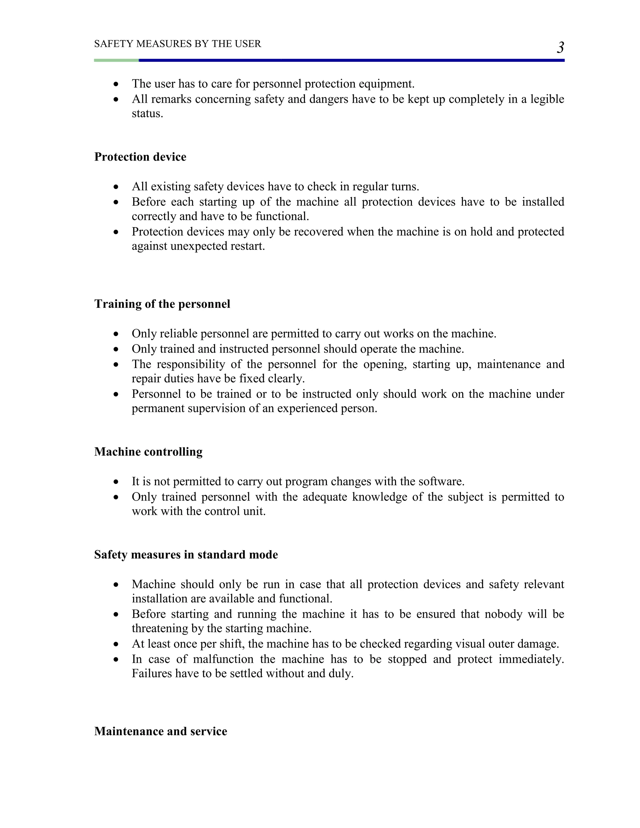
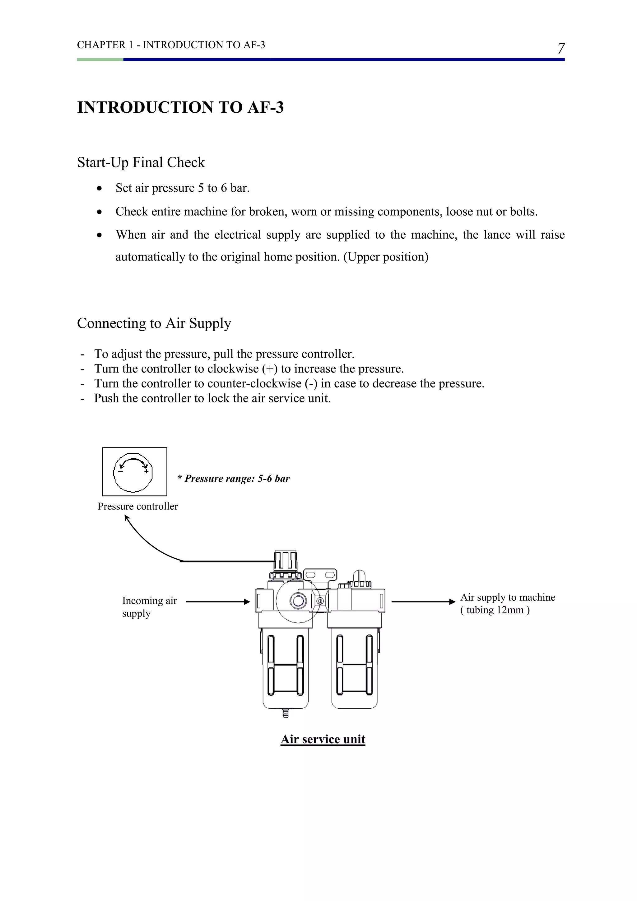
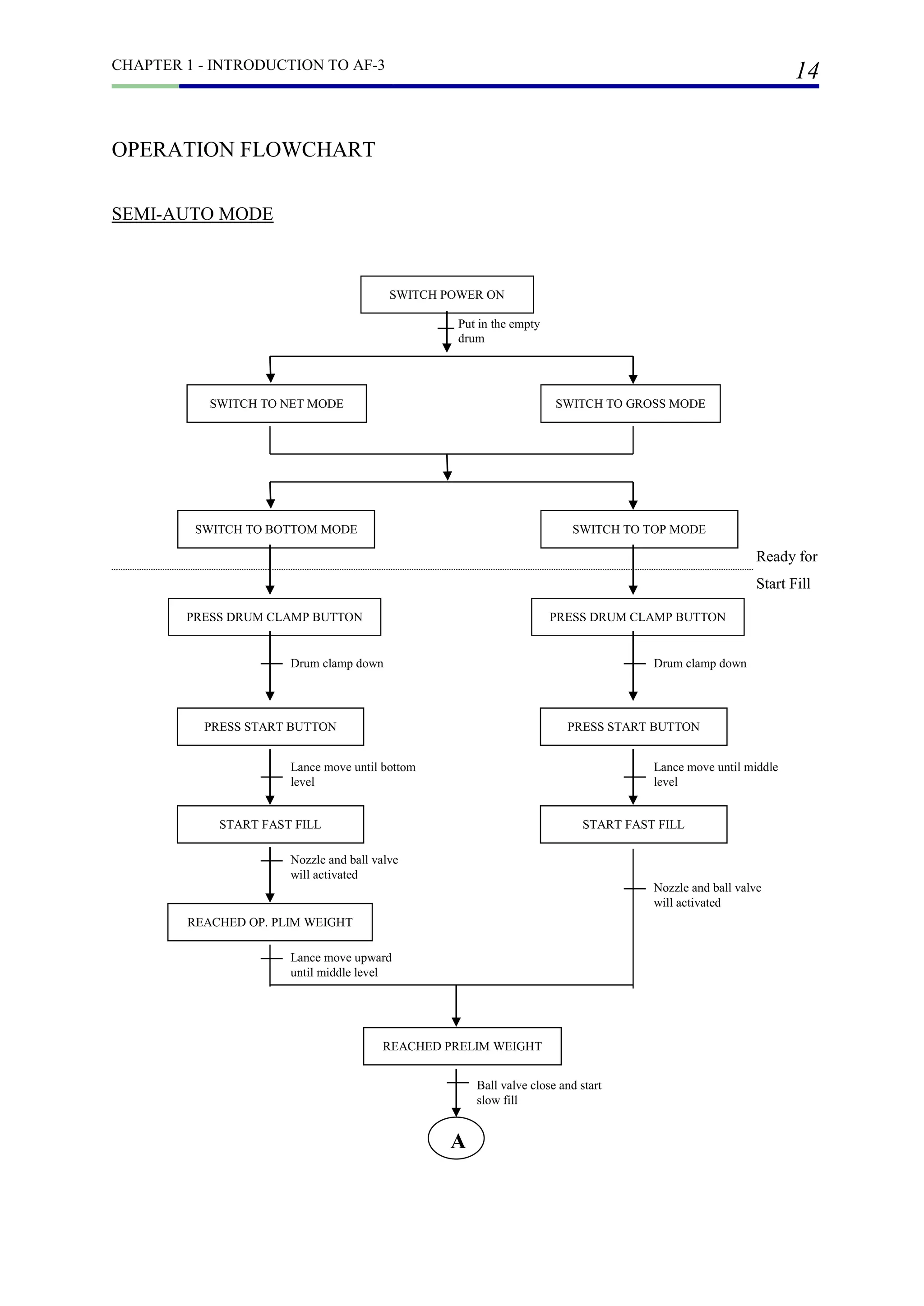
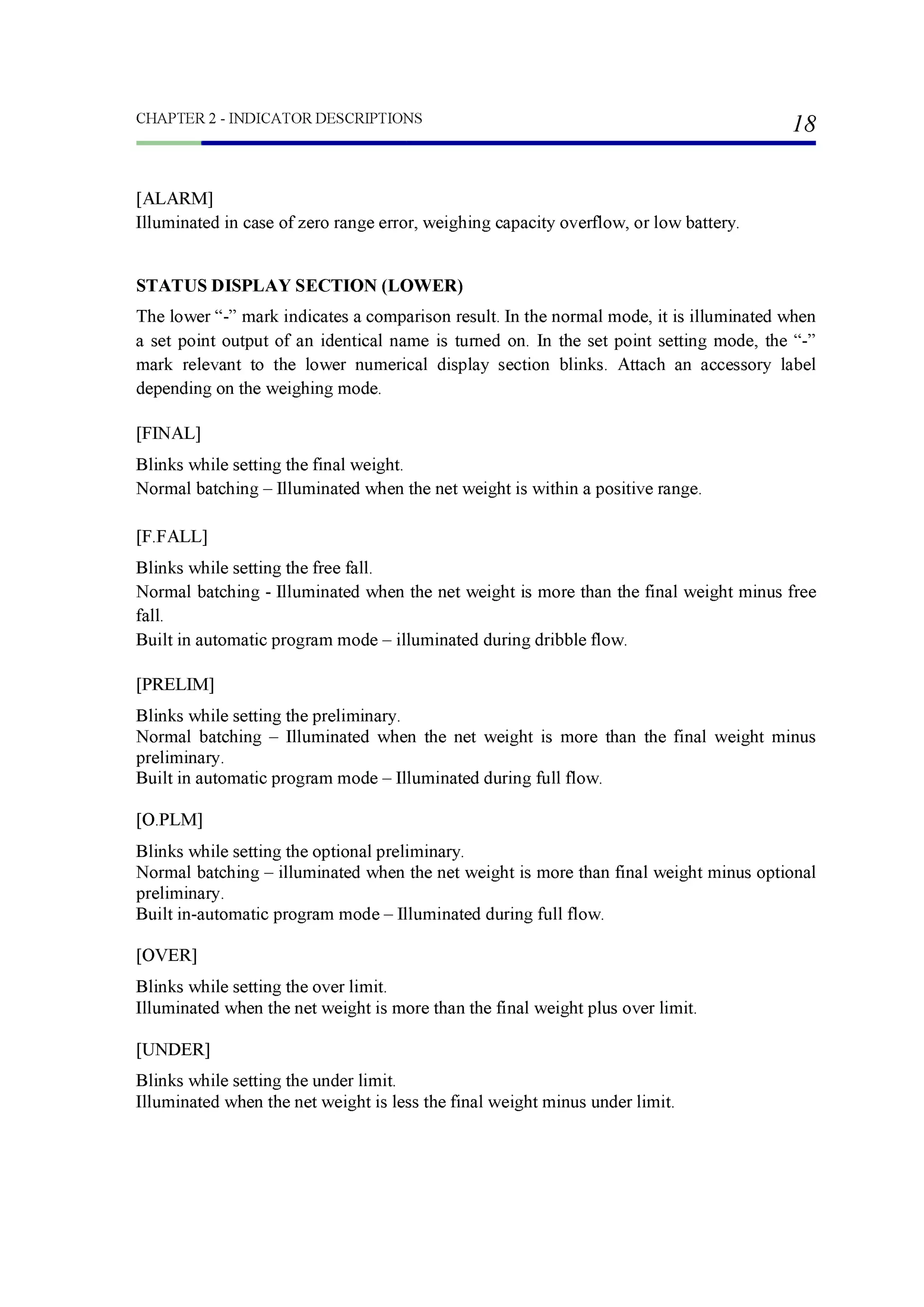
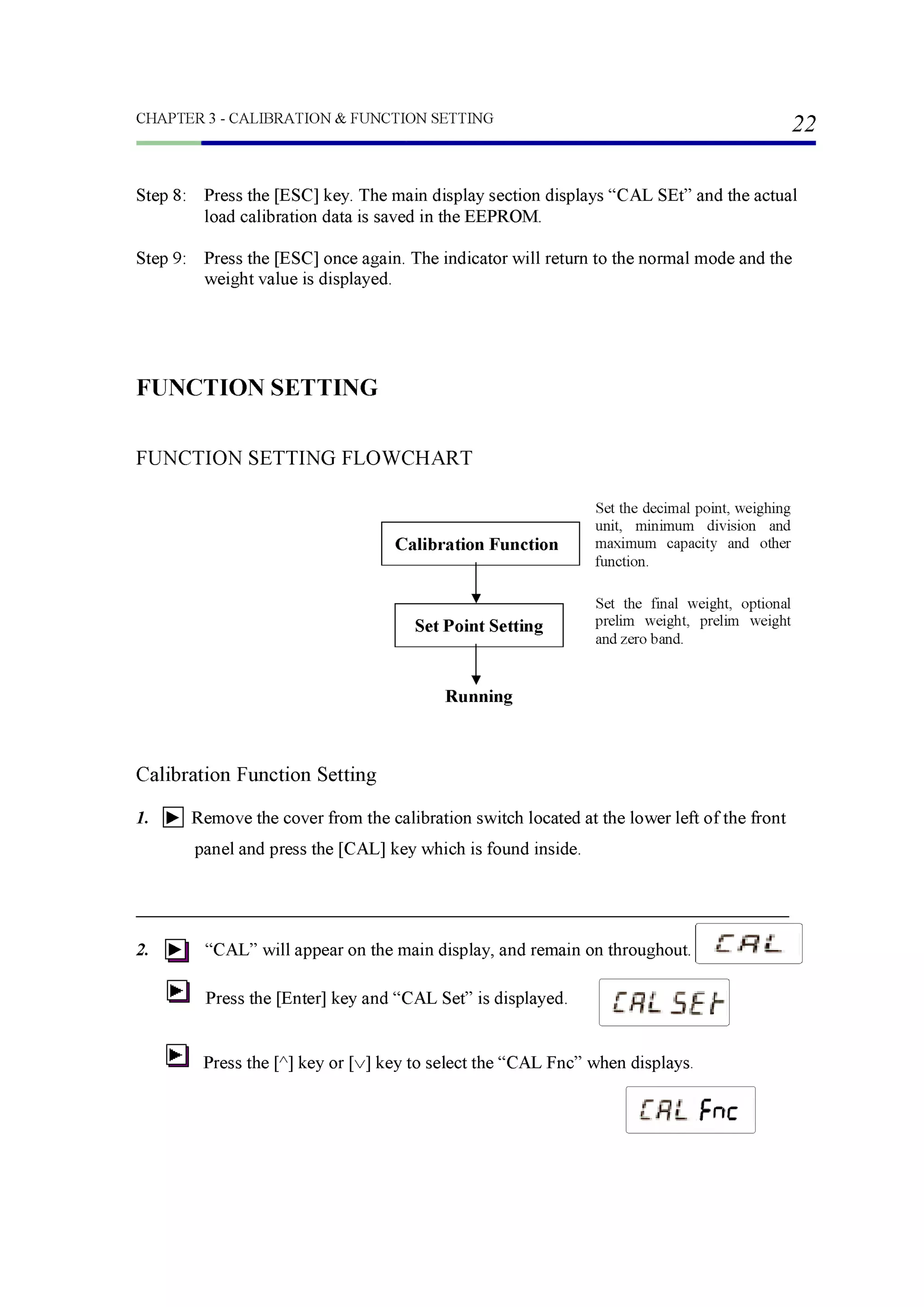
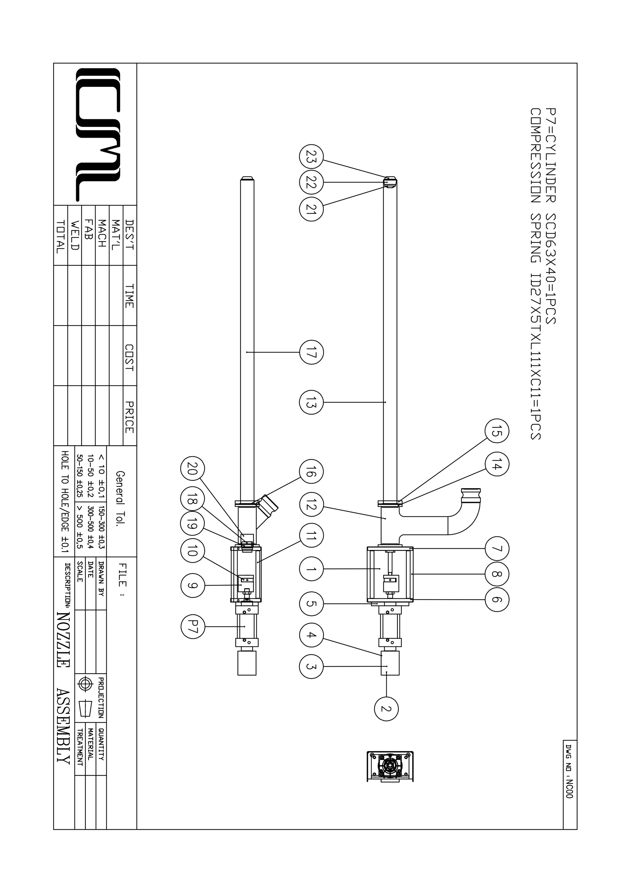
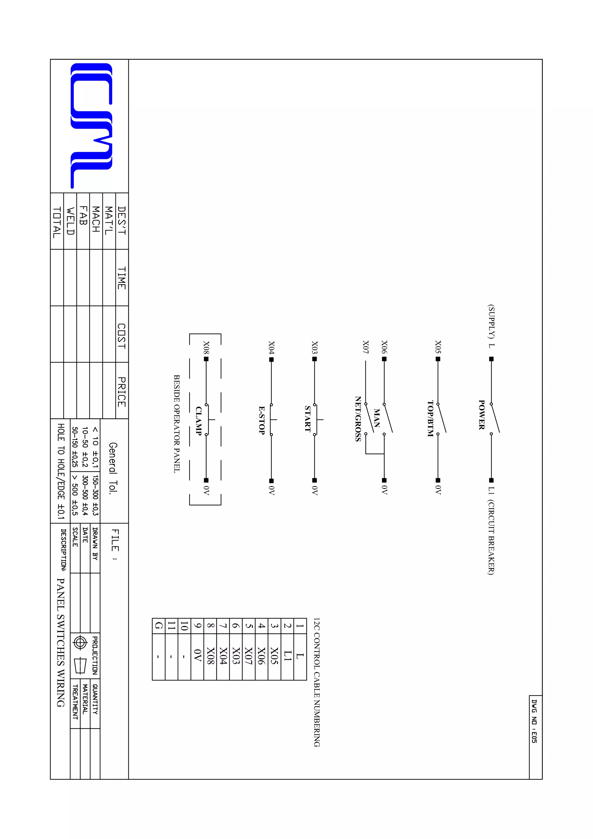
When depressed [START] button, it will start filling operation in auto.
START
TOP
Top mode is mean when the filling action start the lance descends to “MIDDLE” position
(under bunghole) until final weight reached.
BOTTOM
Bottom mode is mean when the filling action start the lance descends to “BOTTOM”
position of drum. While the optional prelim weight is reached, the lance will ascend to
“MIDDLE” position (under bunghole).
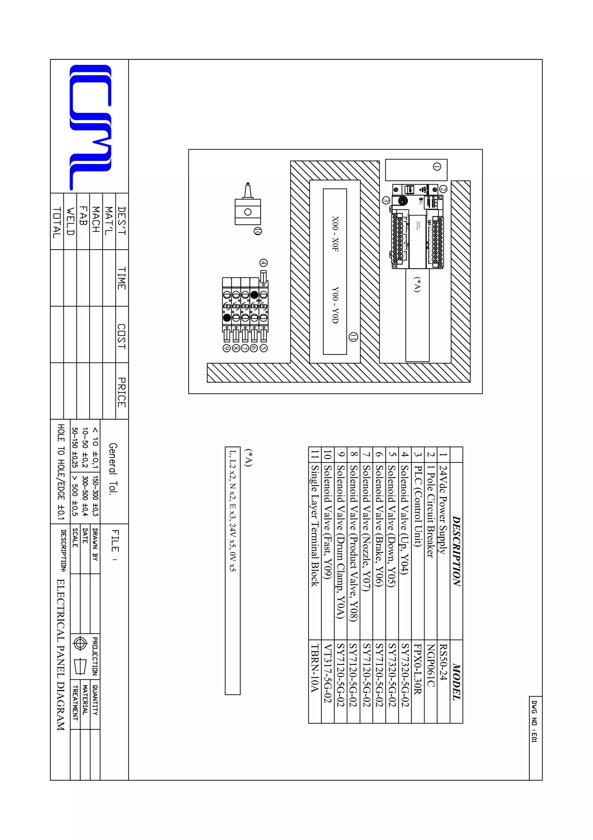
When switched ‘ON’, the switch is illuminated and power is applied to the MCB (switched
‘ON’). The 230V AC power has applied to weighing indicator and 24V DC power supply.
POWER
OFF ON
MODE
TOP BOTTOM
NET
MAN GROSS
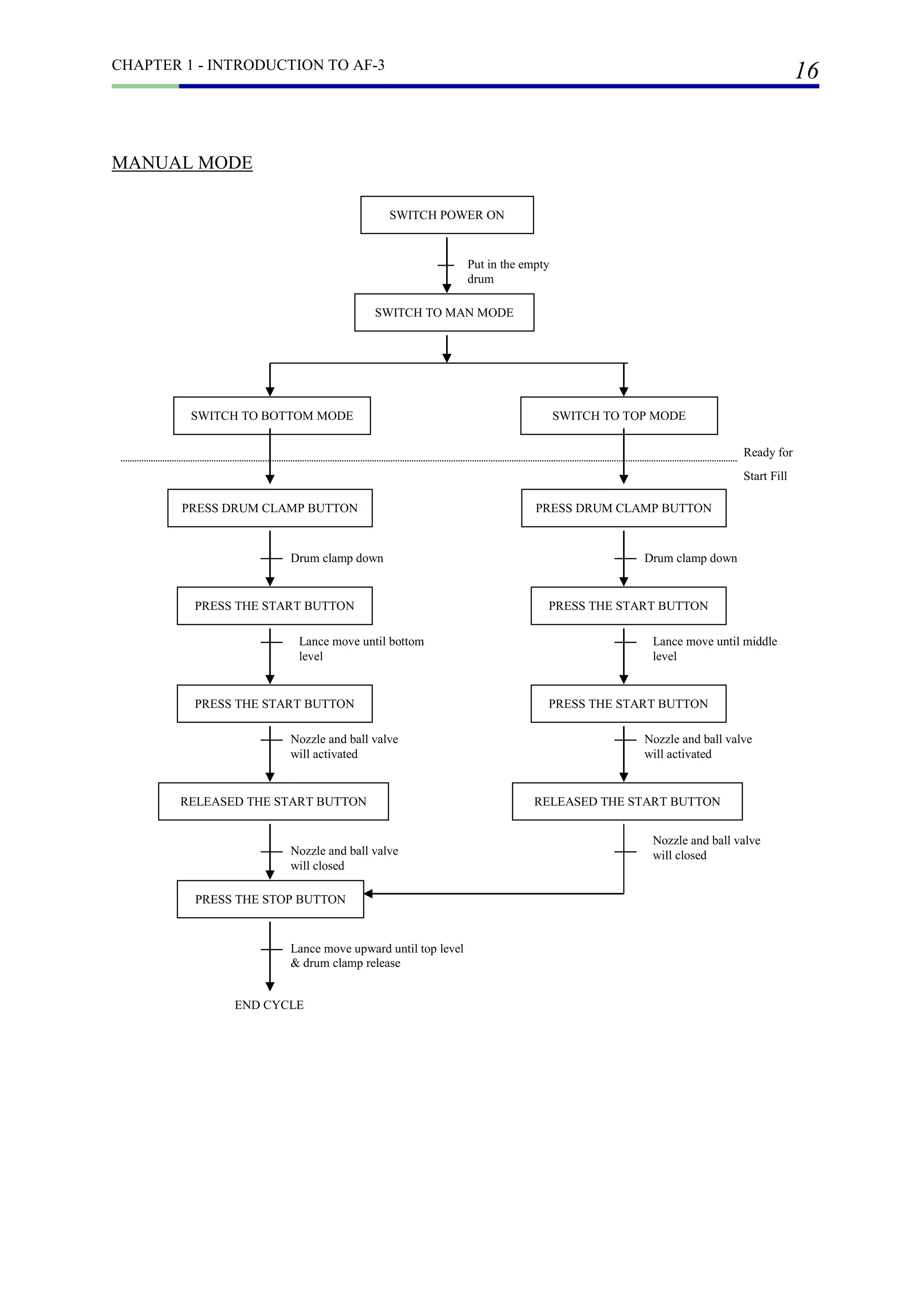
MAN
This is manual mode when operator depressed [START] button, the lance will descends
down to position. Then depressed and hold the [START] button, the nozzle and ball valve
will open. When [START] button is released, the nozzle and ball valve will close. If [E-
STOP] button depressed, the lance will ascends to “UP” or “HOME” position.
NET
This is “NET” fill with auto tare. When empty drum placed into the weighing platform, the
weighing indicator will register the empty drum weight. When in this mode after depressed
the [START] button, the indicator will tare the empty drum weight and display will return
to 0.0KG but it is at “NET” reading.
GROSS
This is “GROSS” fill without tare. The empty drum weight is not tare and the display is at
“GROSS” reading.](https://image.slidesharecdn.com/af3-instructionmanual-cmspecialist-180919151900/75/Af3-instruction-manual-cm-specialist-14-2048.jpg)
![CHAPTER 1 - INTRODUCTION TO AF-3
12
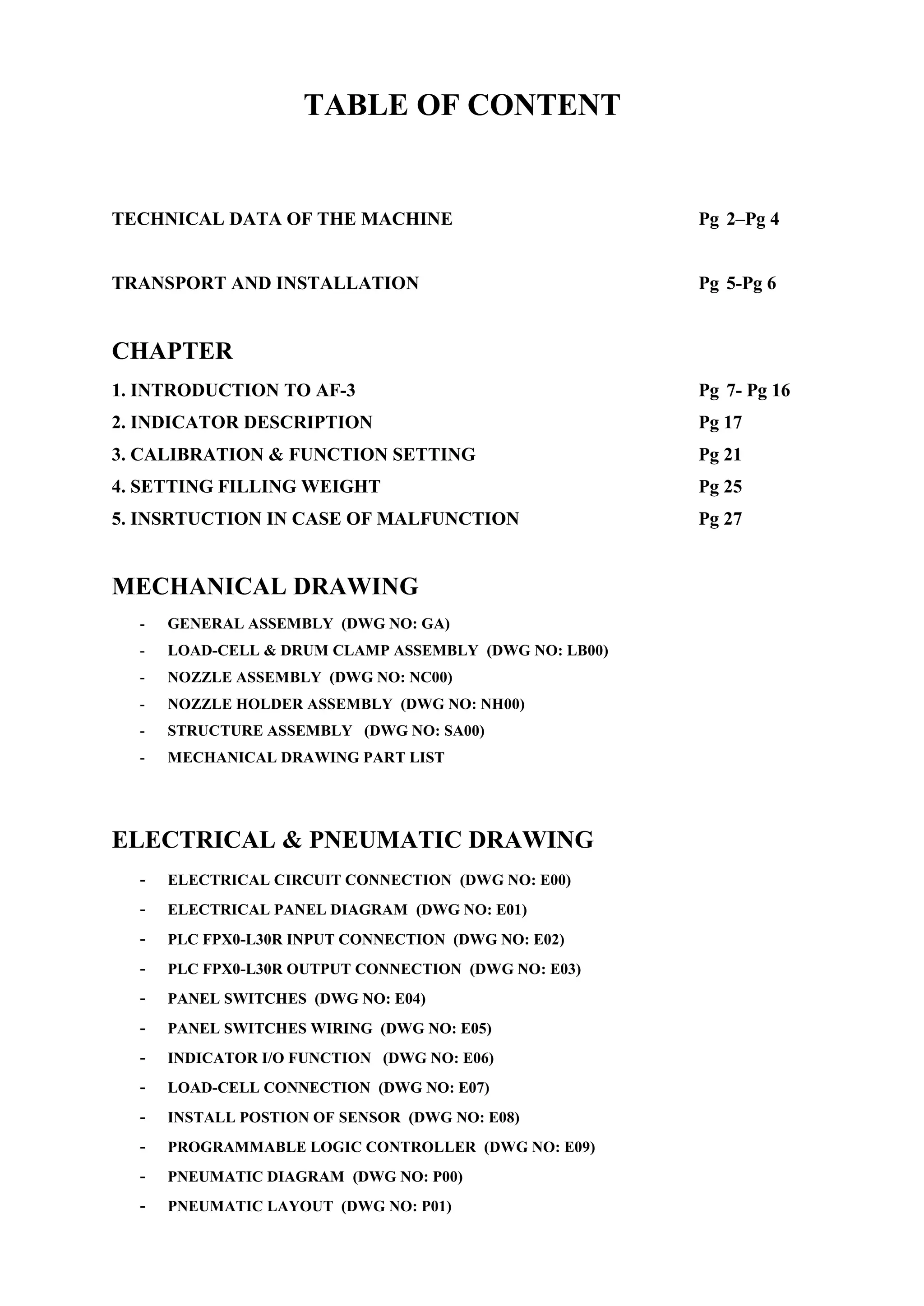
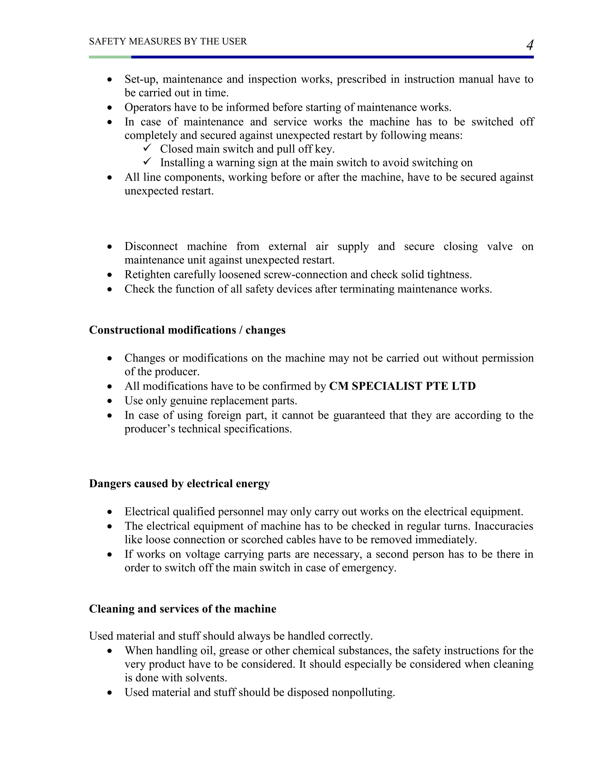
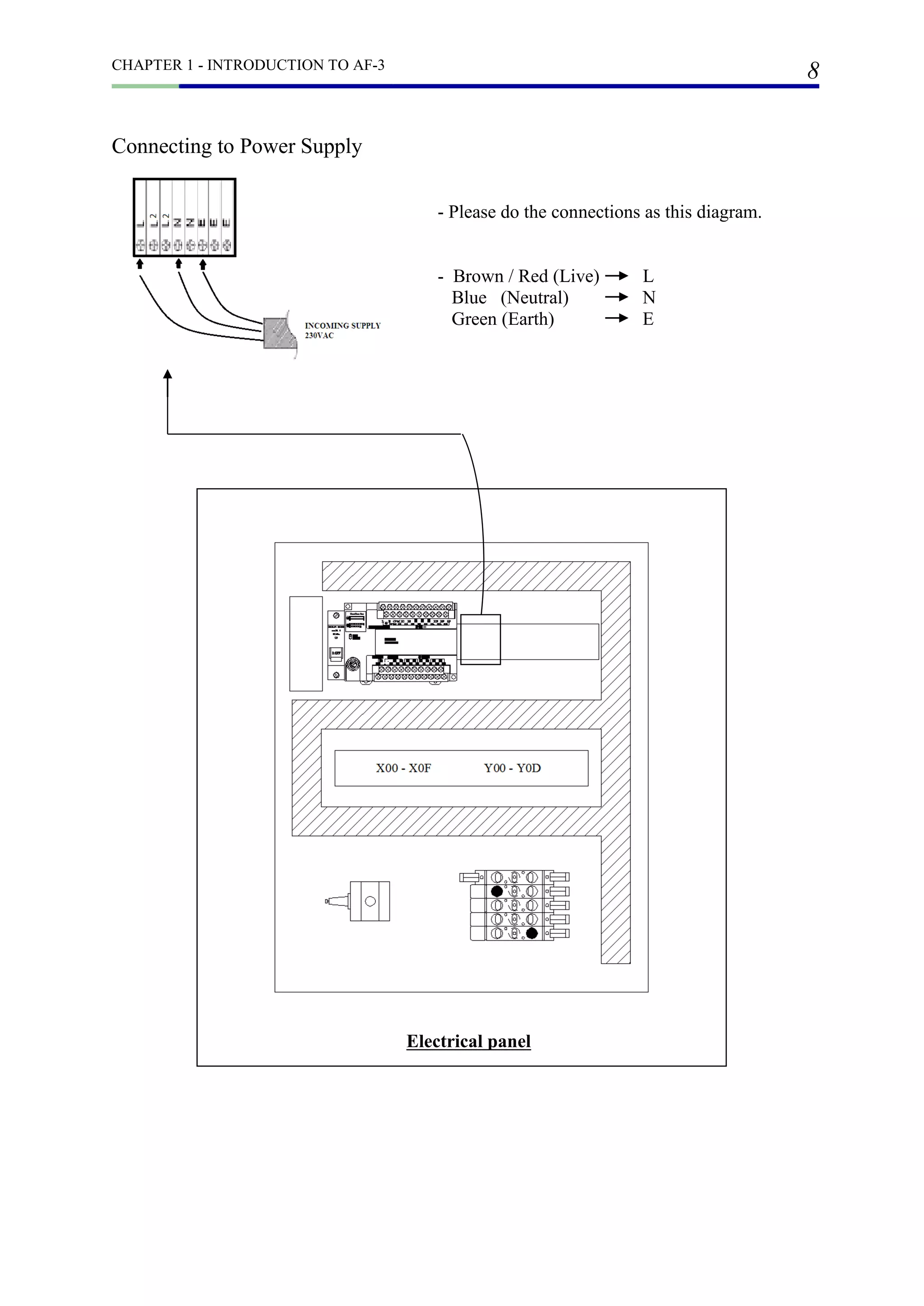
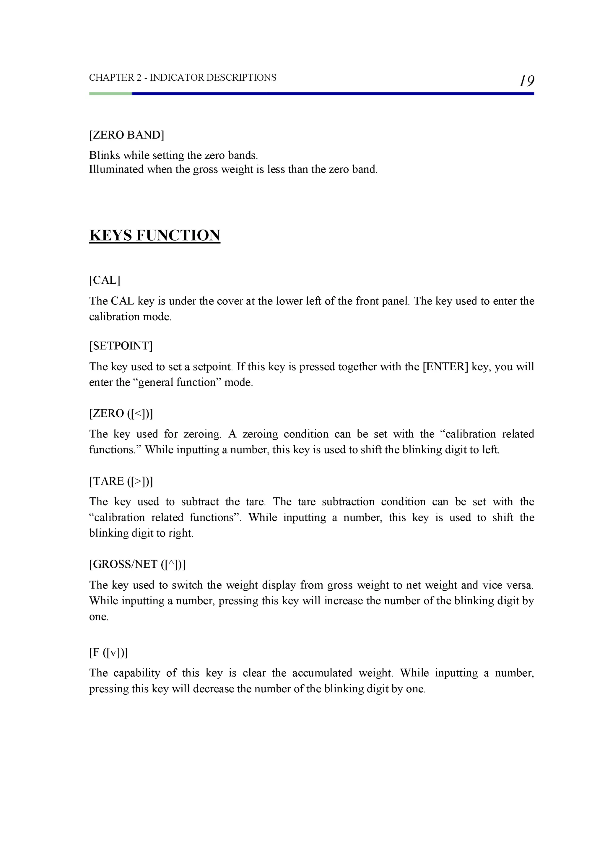
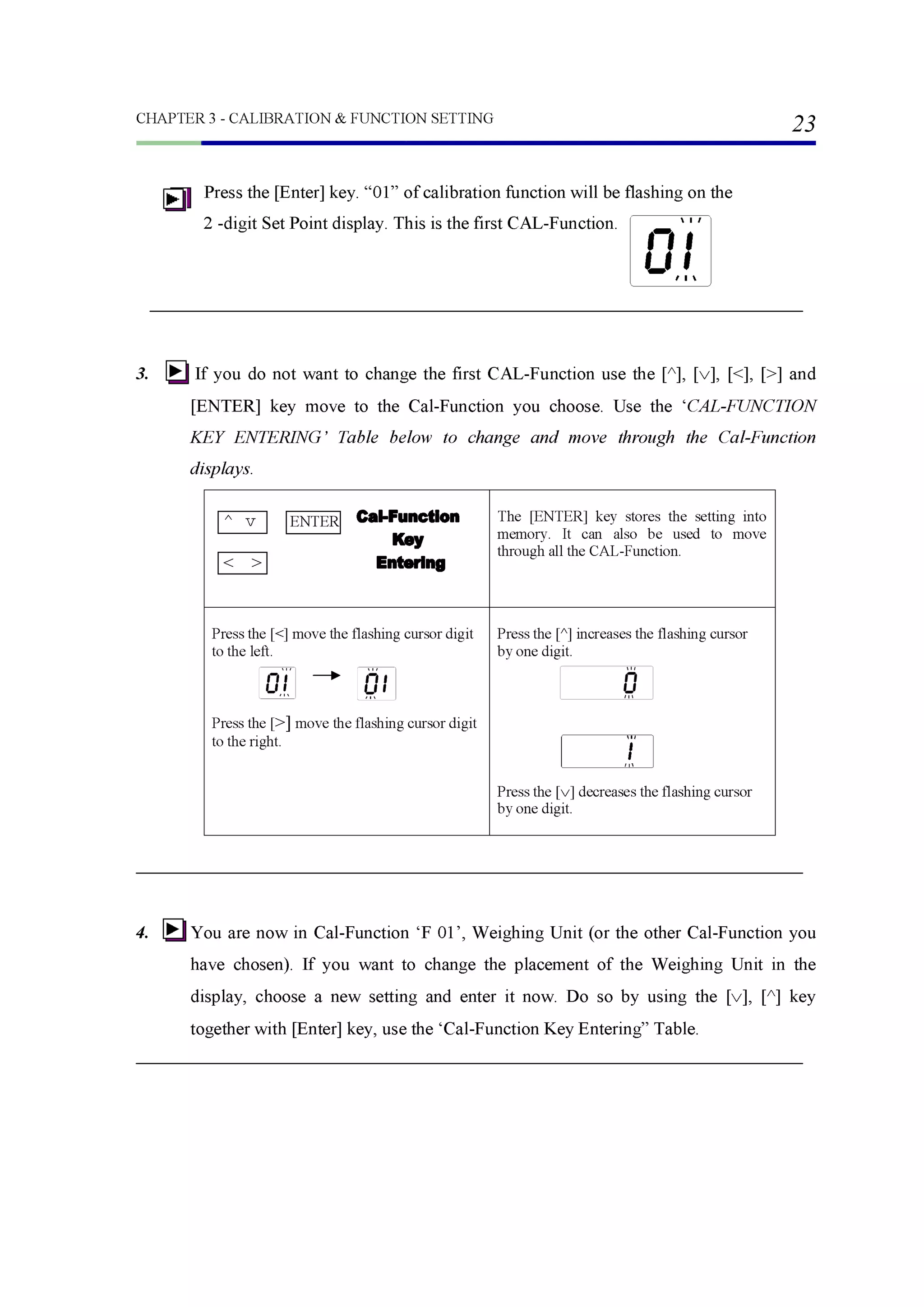
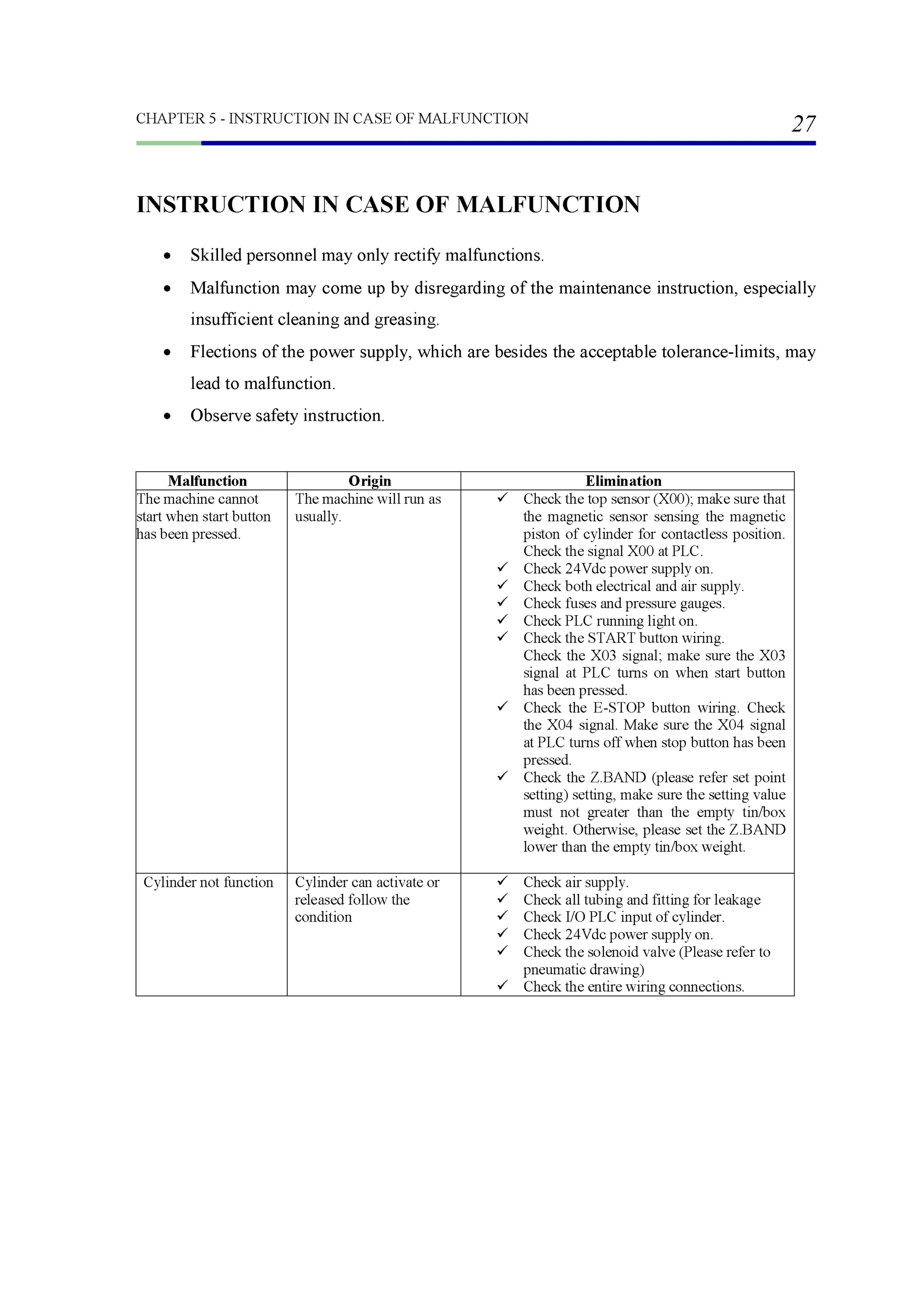
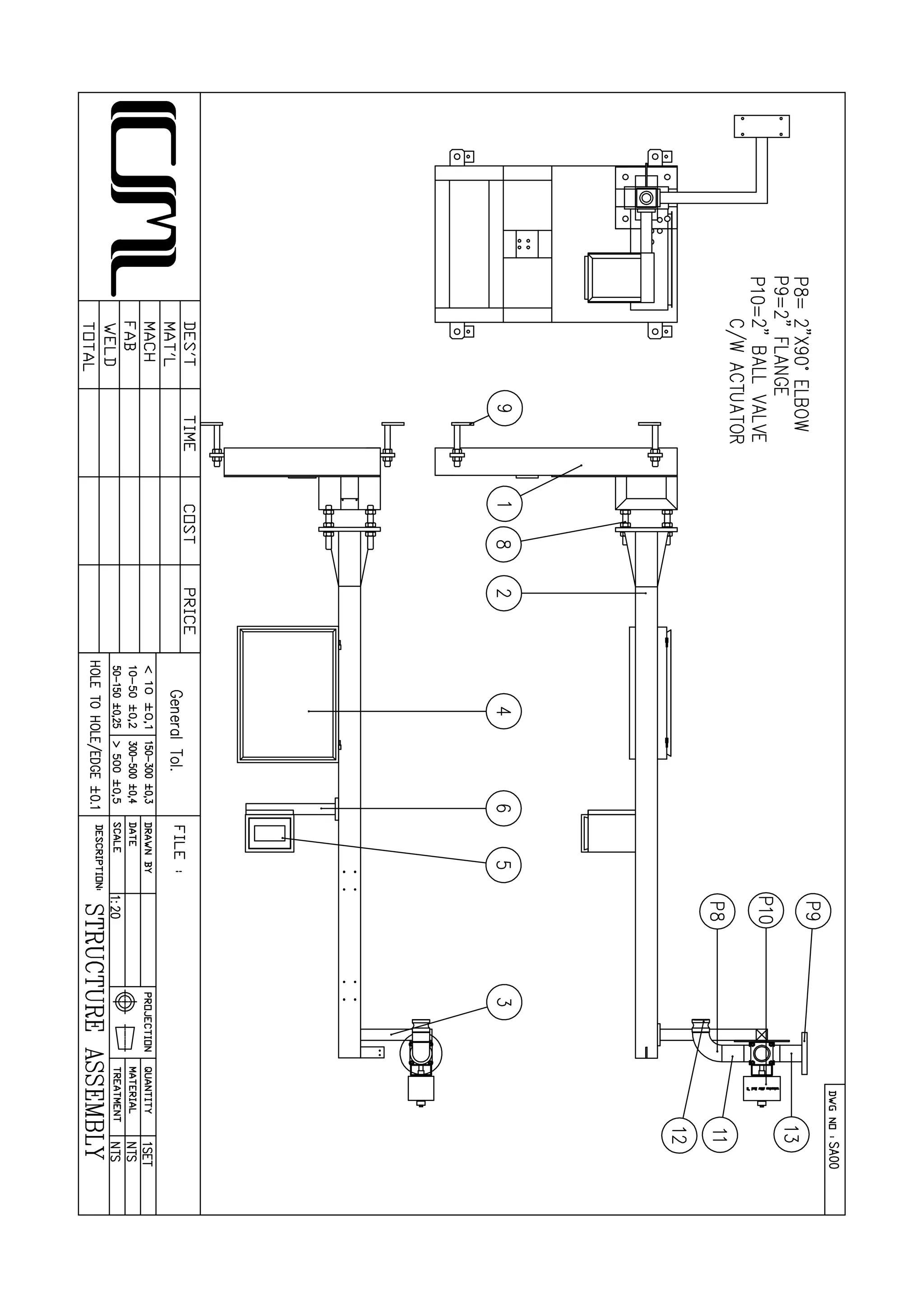
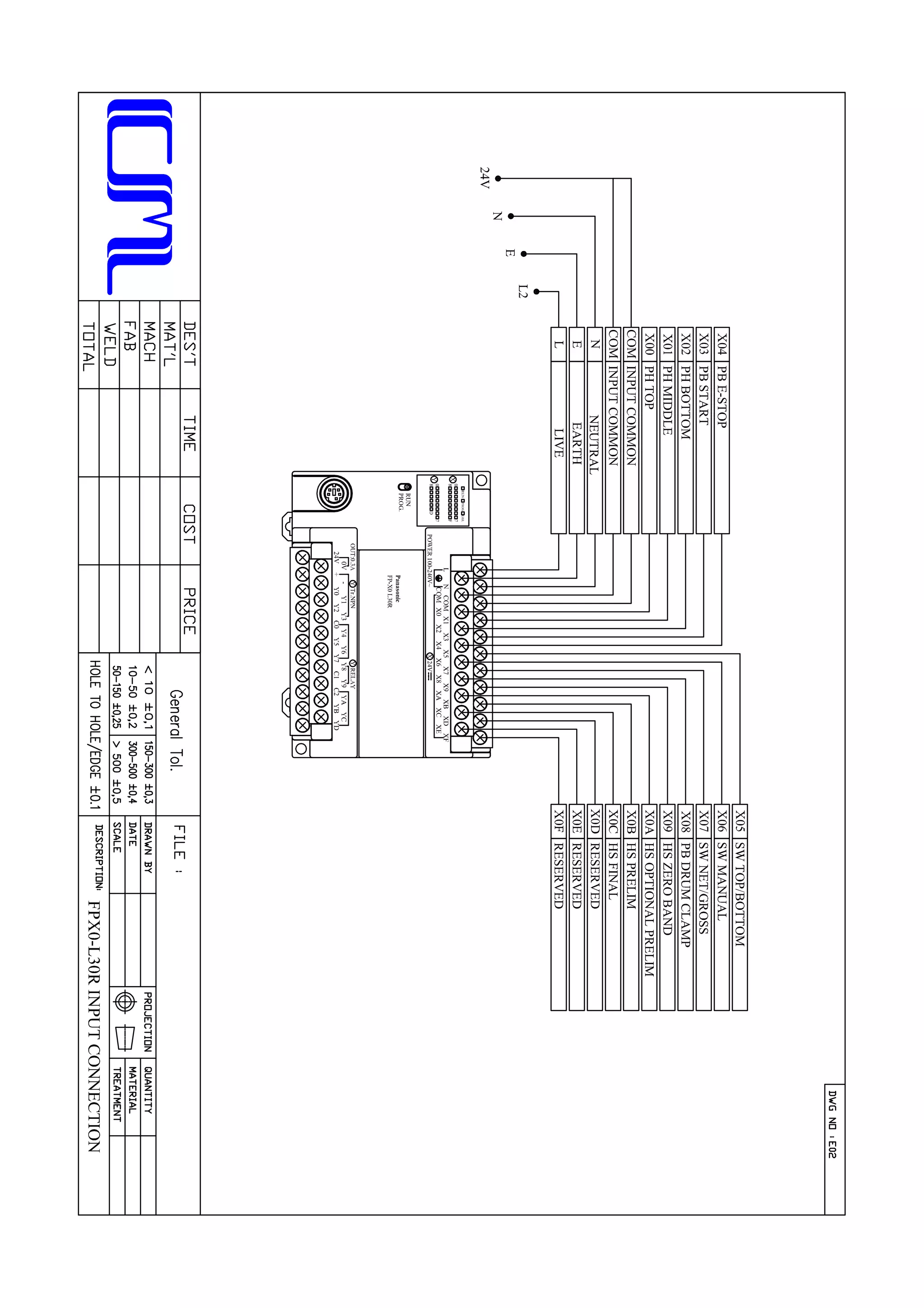
In case of emergency, when depressed [E-STOP] button, entire machine will stop all the
operation. The nozzle and ball valve will close; the lance will retract back to “UP” or
“HOME” position.
E - STOP
DRUM CLAMP
When depressed [DRUM CLAMP] button, the drum clamp device will clamp the
bunghole of drum.](https://image.slidesharecdn.com/af3-instructionmanual-cmspecialist-180919151900/75/Af3-instruction-manual-cm-specialist-15-2048.jpg)
![CHAPTER 1 - INTRODUCTION TO AF-3
13
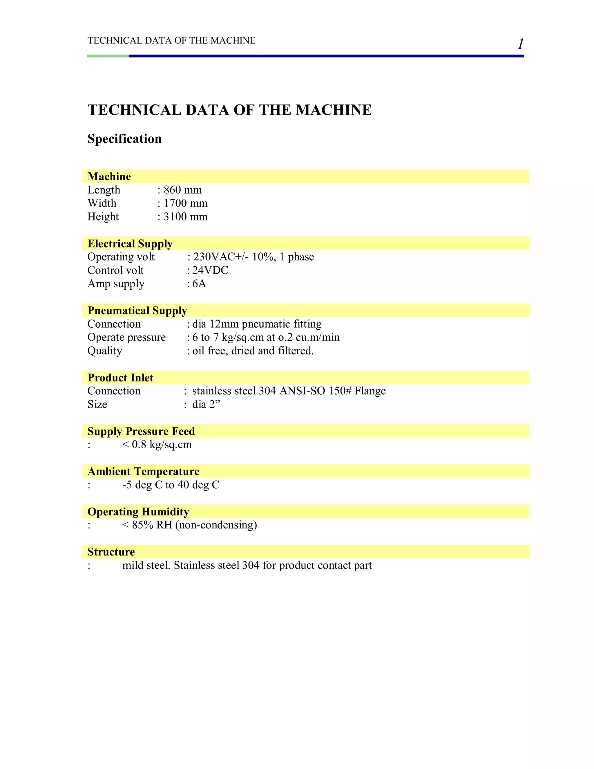
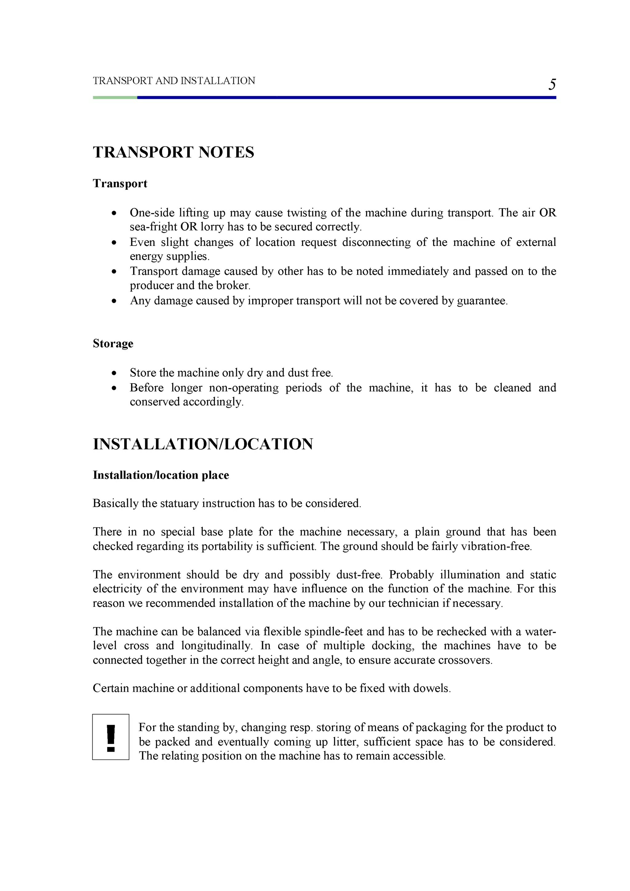
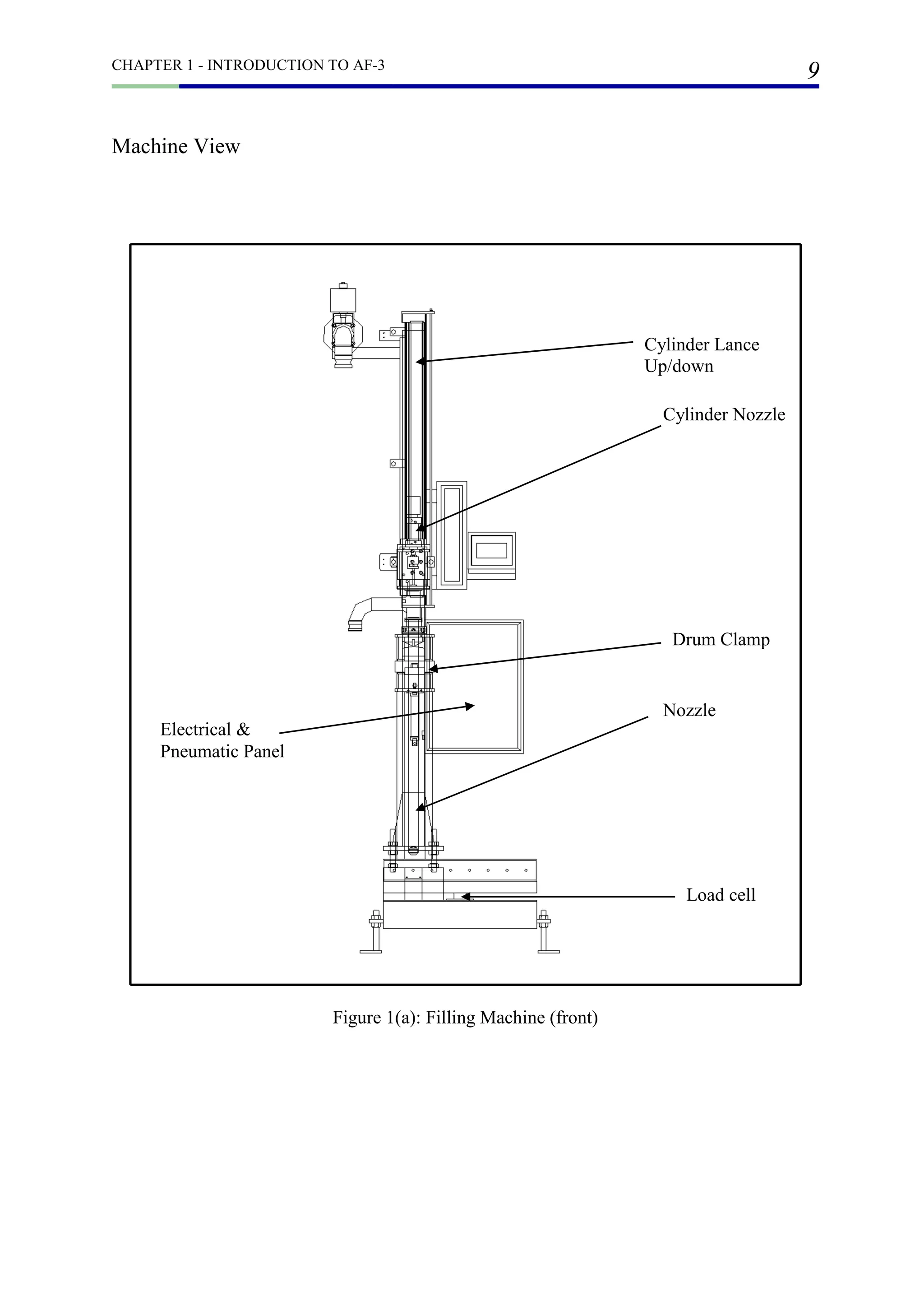
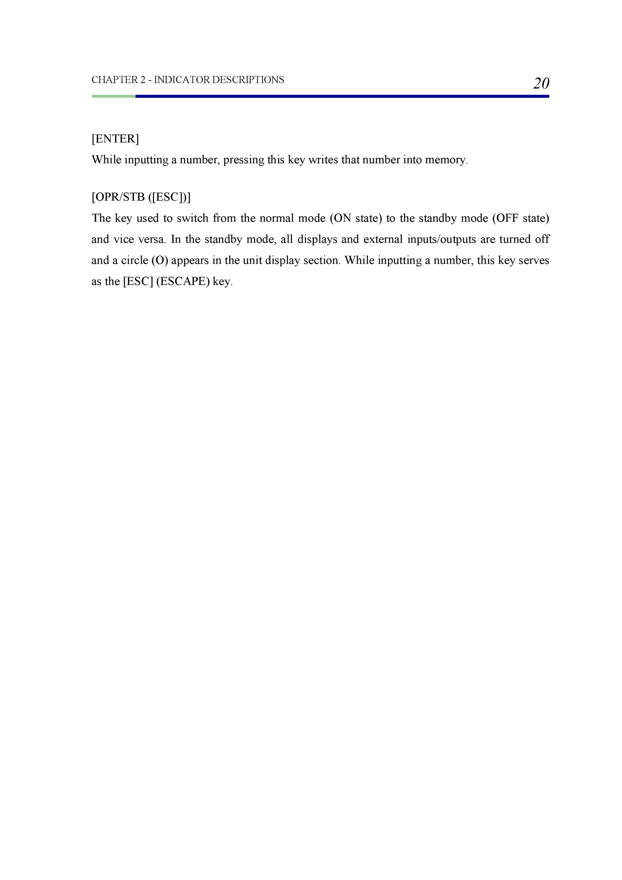
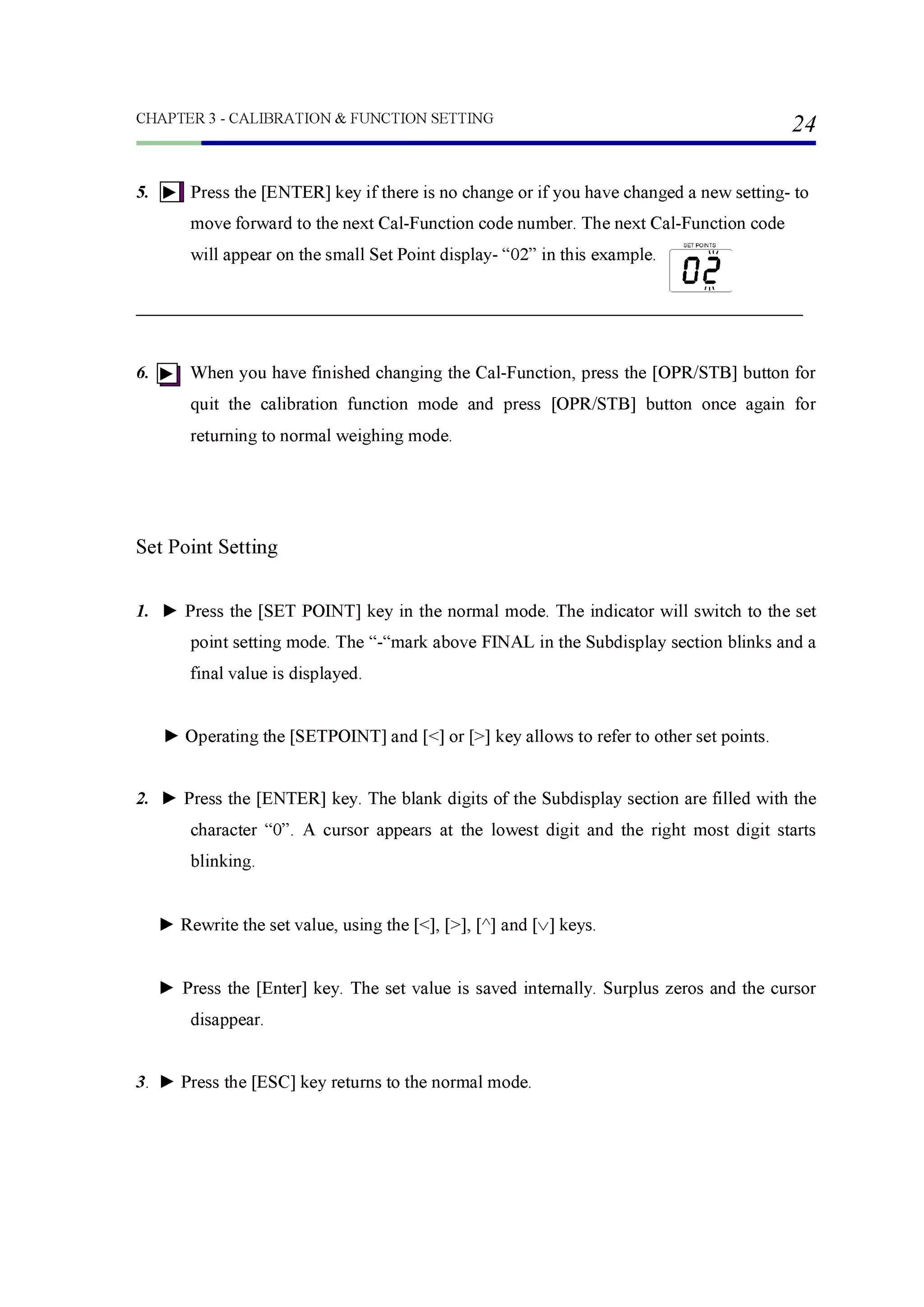
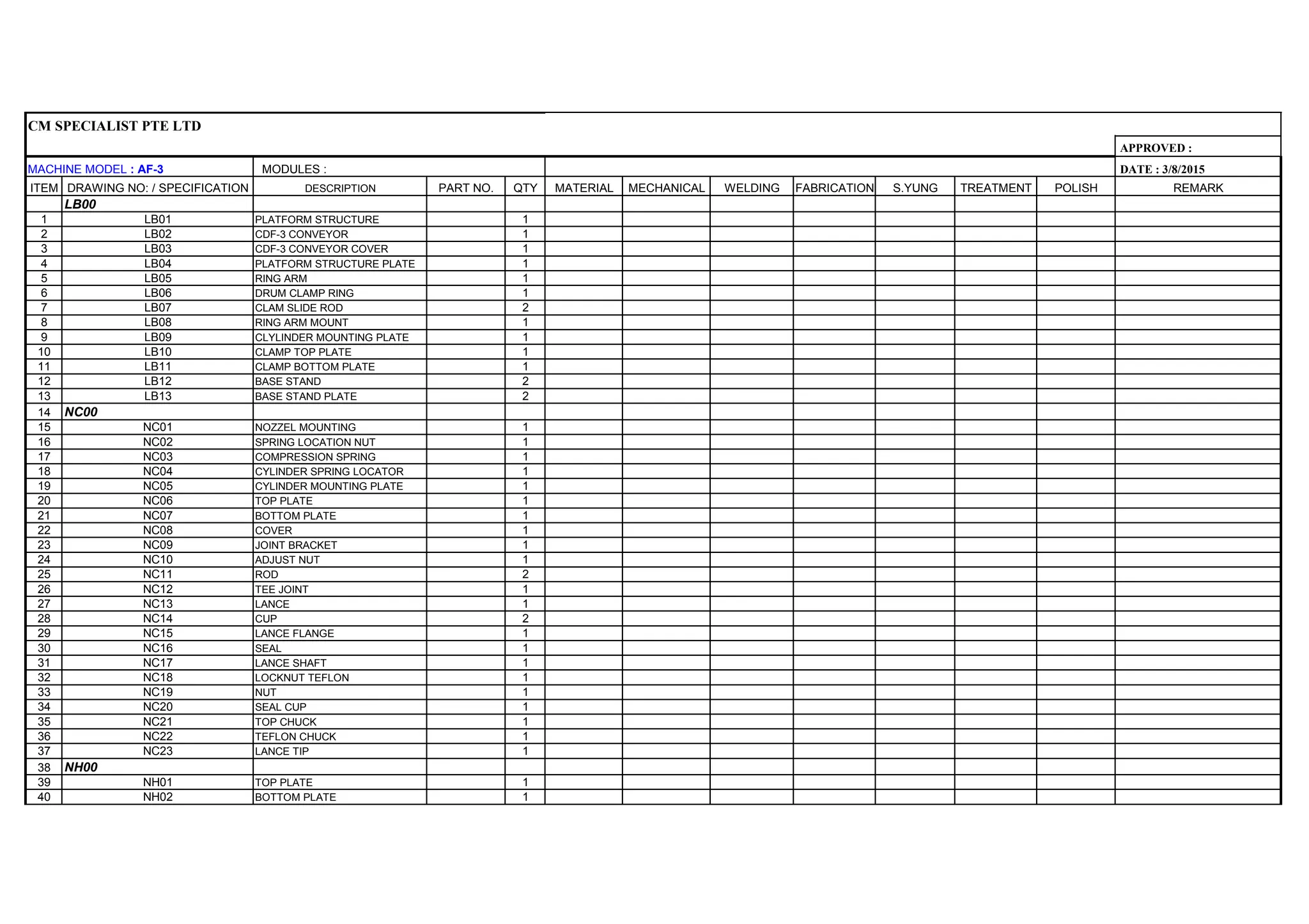
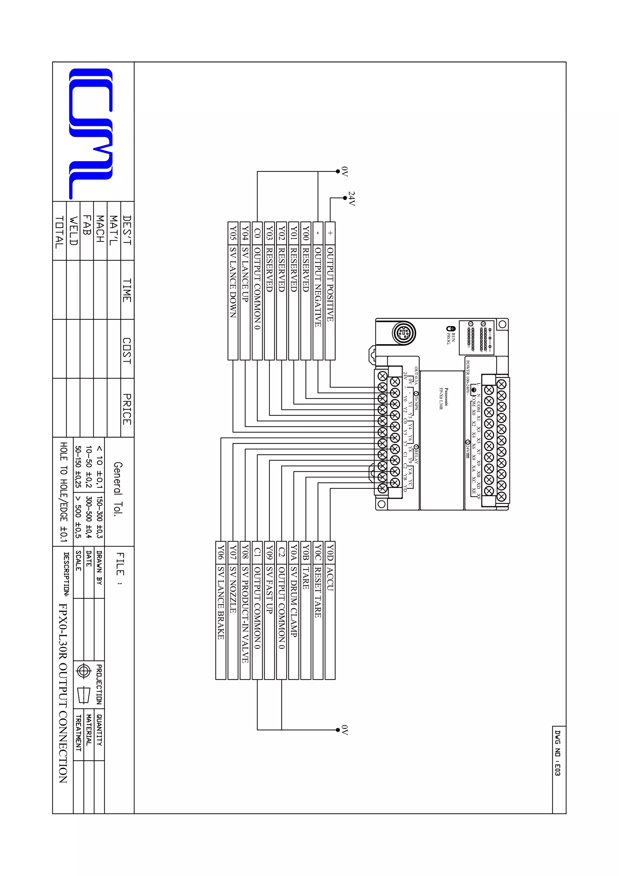
Operation Procedures
With nothing on the weighing platform, the digital weighing indicator should indicate
0.0kg. If the display is not at 0.0kg, press the [ZERO] button on the weighing indicator
to get 0.0kg.
Operator preset on weighing indicator for desired “ZERO BAND”, “OPTIONAL
PRELIM”, “PRELIM”, “FINAL” and “FREE FALL” (if needed) value for filling.
When the empty drum placed into the weighing platform, the operator will depress
[DRUM CLAMP] button to locate the bunghole position. Then press [START] button.
If bottom mode, the lance will descend to “BOTTOM” position or if top mode, the
lance will descends to “MIDDLE” position. If the operation in “GROSS” modes, the
empty drum wills not tare and indicator display is at “GROSS” reading. If the
operation in “NET” mode, the empty drum weight will auto tare to 0.0kg before start
filling, but it is “NET” reading.
At the top mode, the filling operation start fill product into drum, while the lance
descends to “MIDDLE” position which is approx. 50mm below the bunghole.
At the bottom mode, the filling operation start fill product into drum, while the lance
descends to bottom position of the drum, and raise to middle position, when the
optional prelim weight was reach.
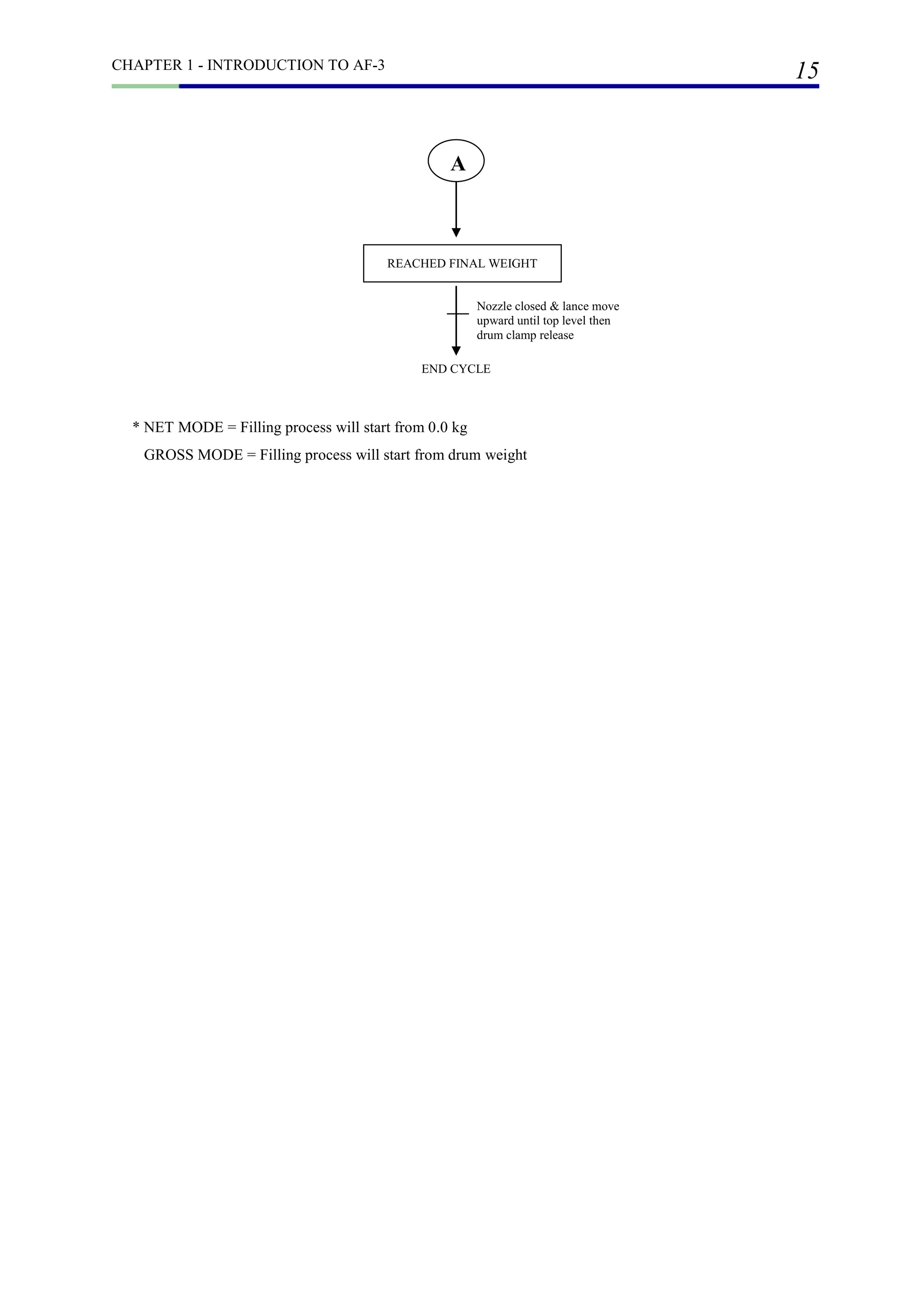
When the “PRELIM” weight is reached, the ball valve will close and slow fill will be
activated to reduce the flow rate.
When the “FINAL” weight is reached, the nozzle will close completely. And the lance
device will ascend back to “UP” or “HOME” position.](https://image.slidesharecdn.com/af3-instructionmanual-cmspecialist-180919151900/75/Af3-instruction-manual-cm-specialist-16-2048.jpg)
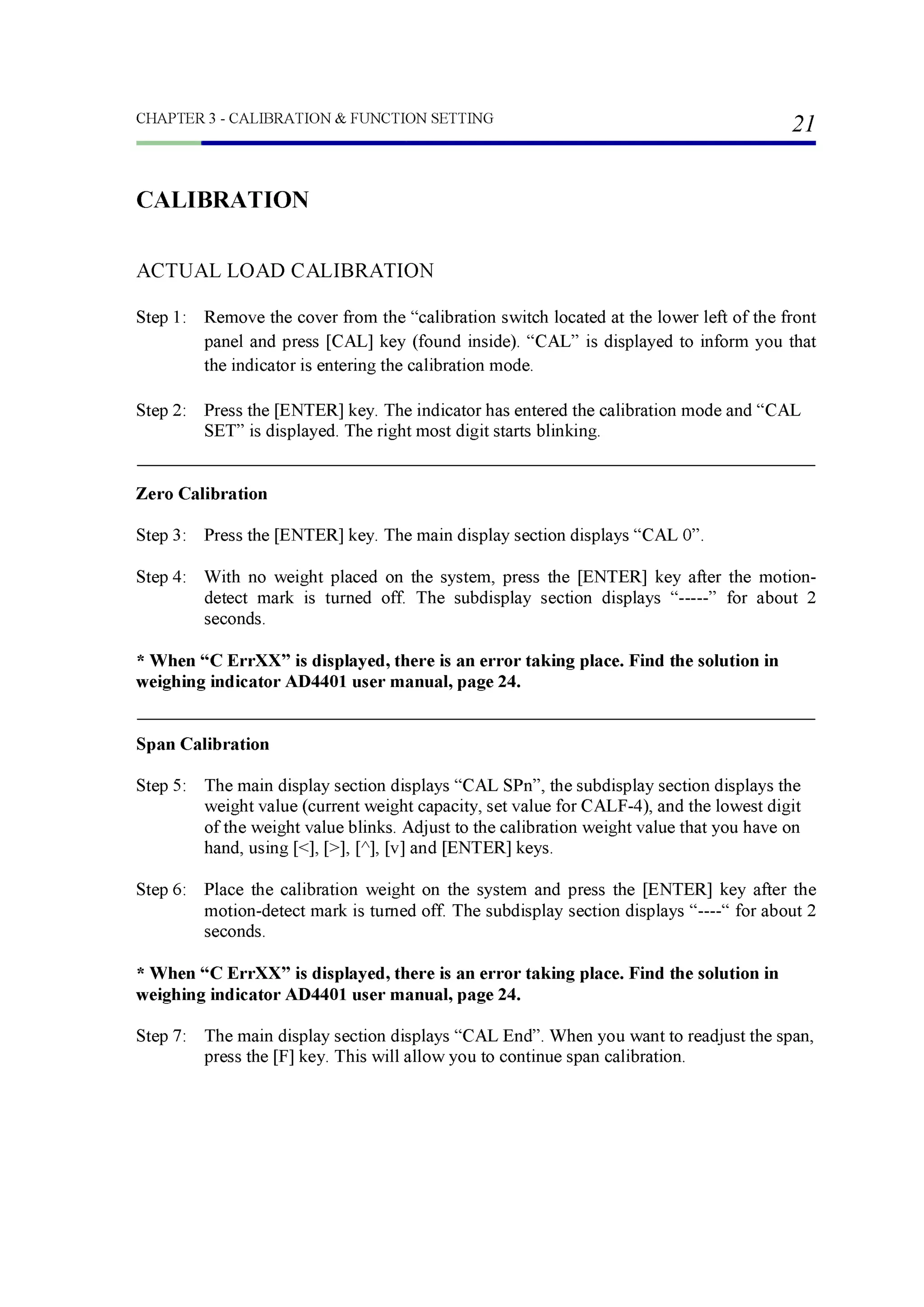

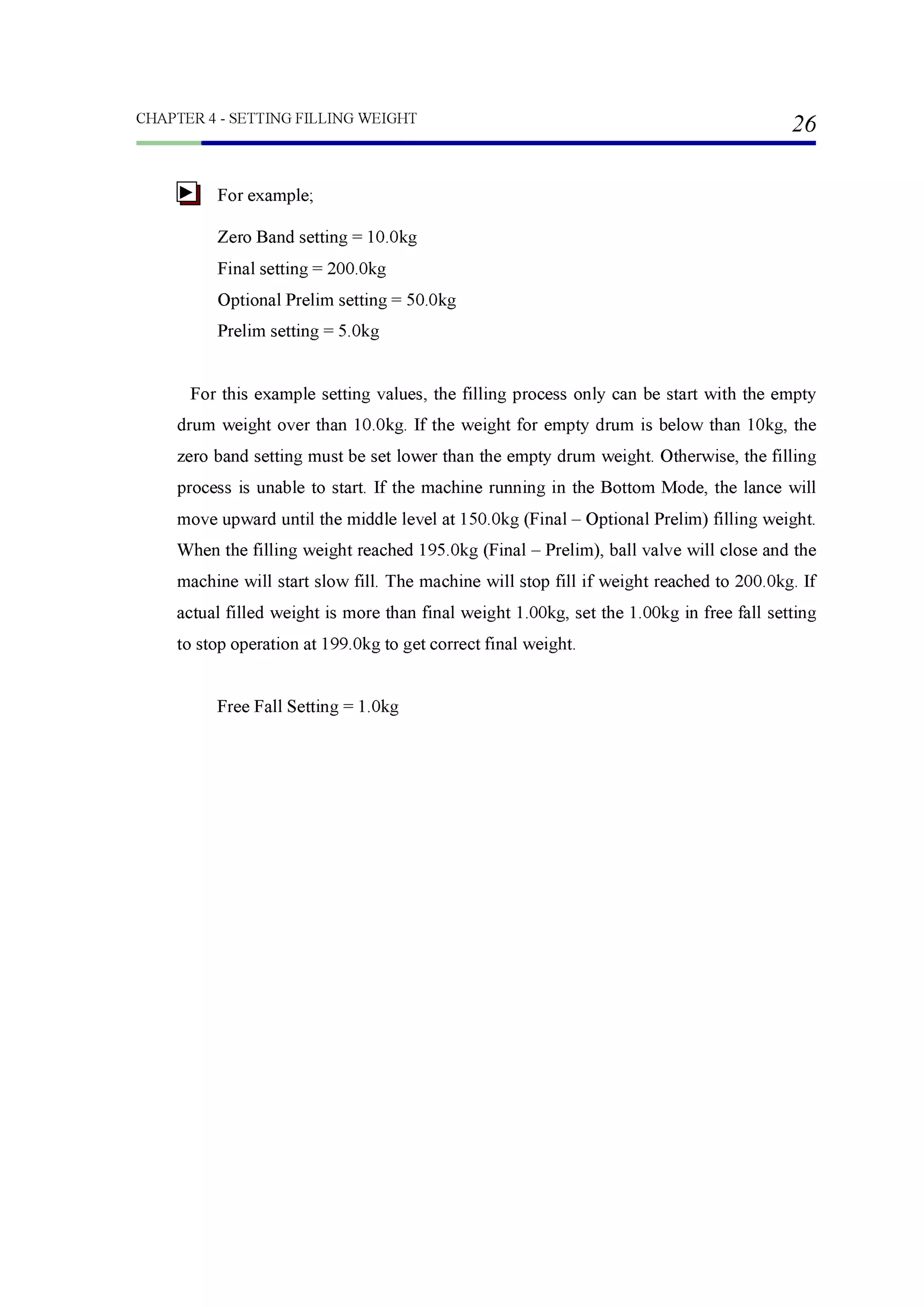


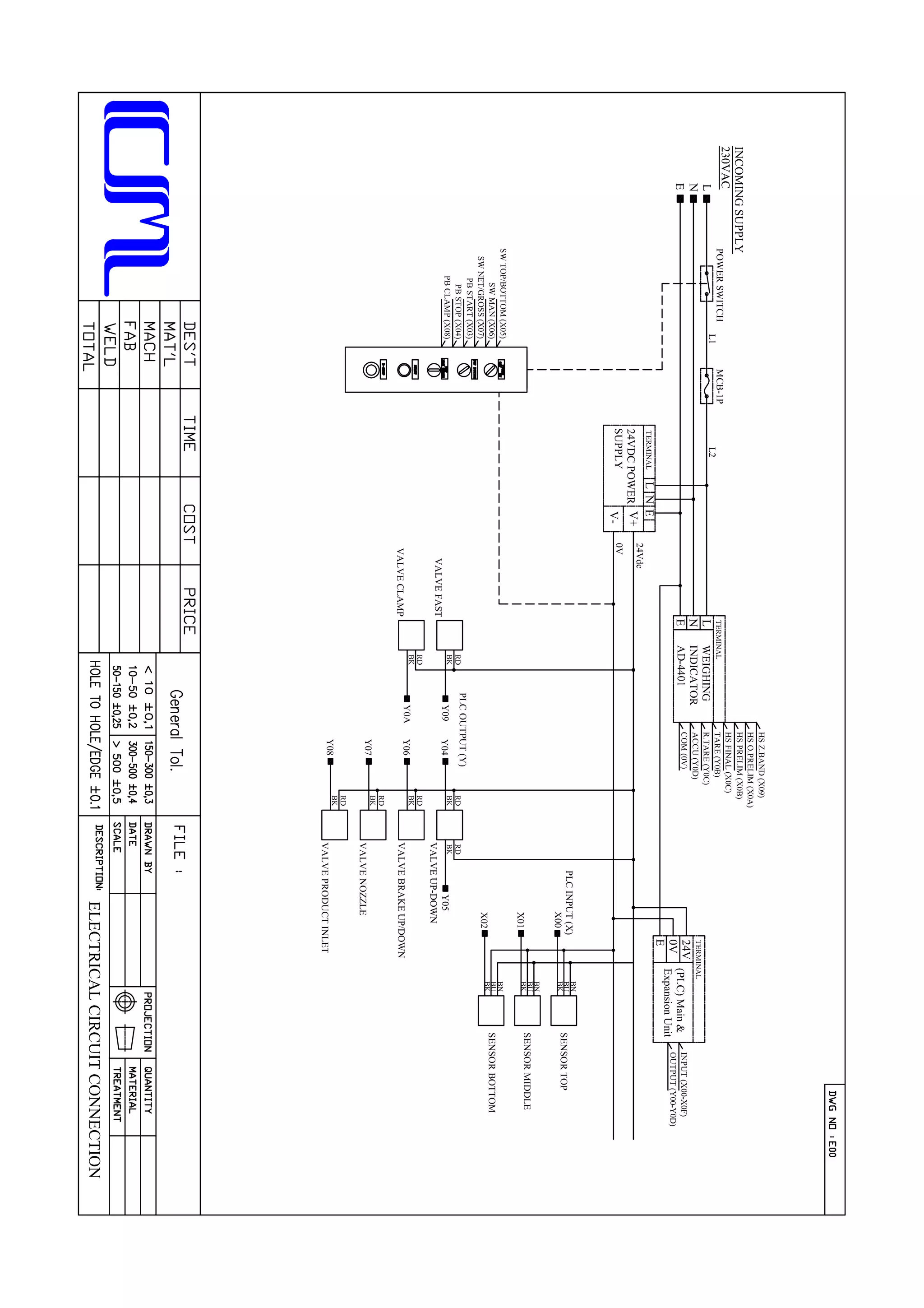
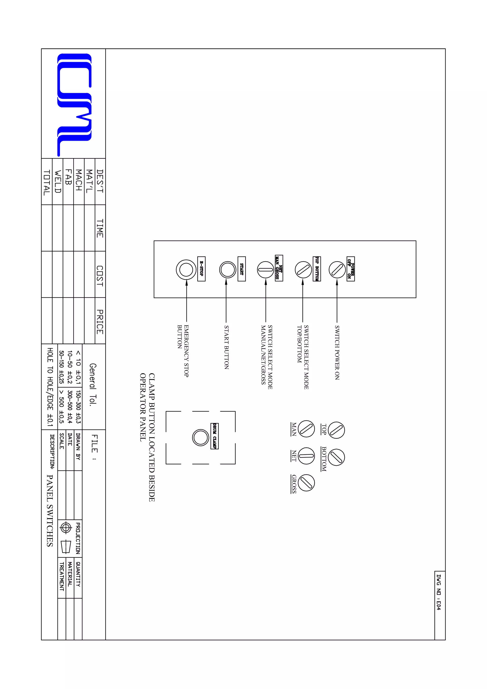


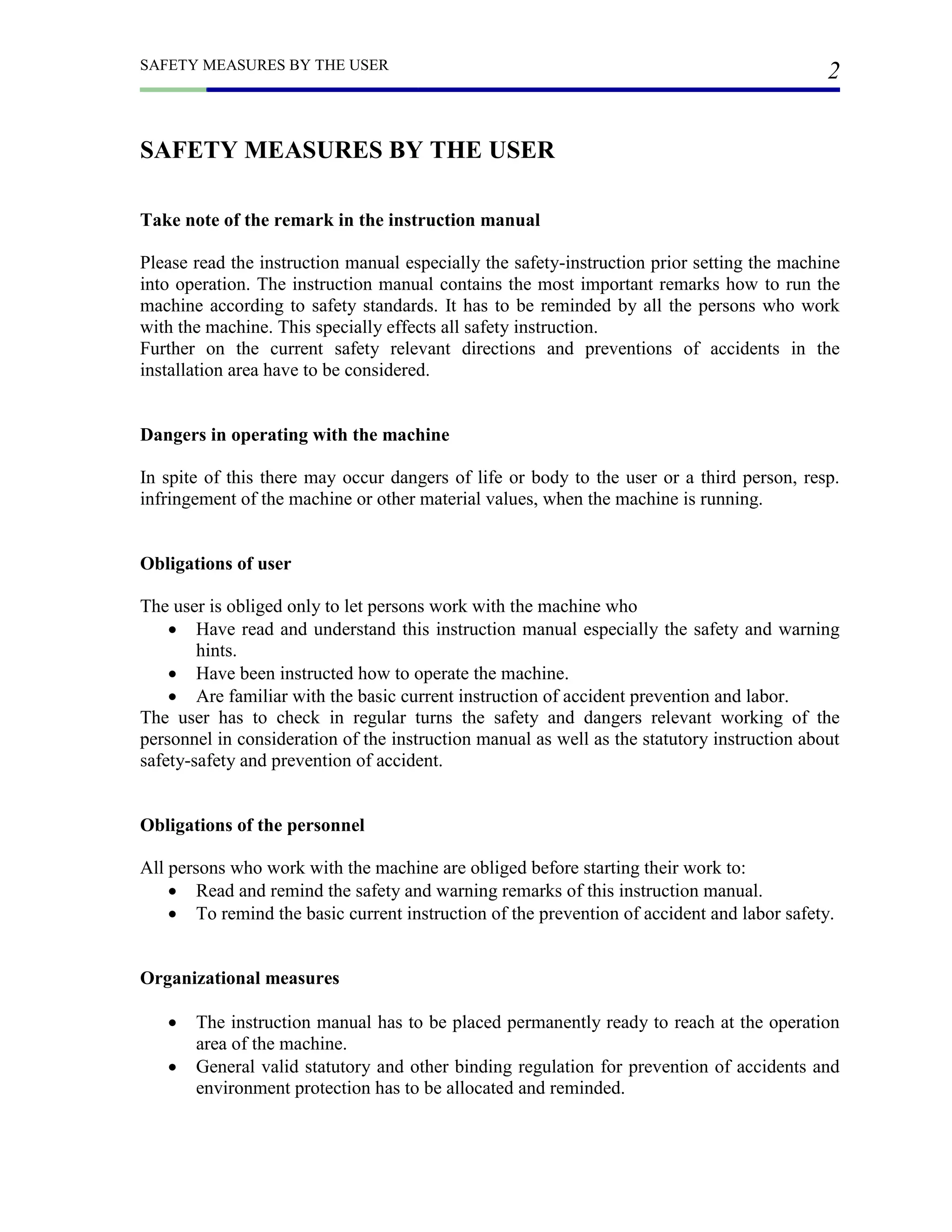
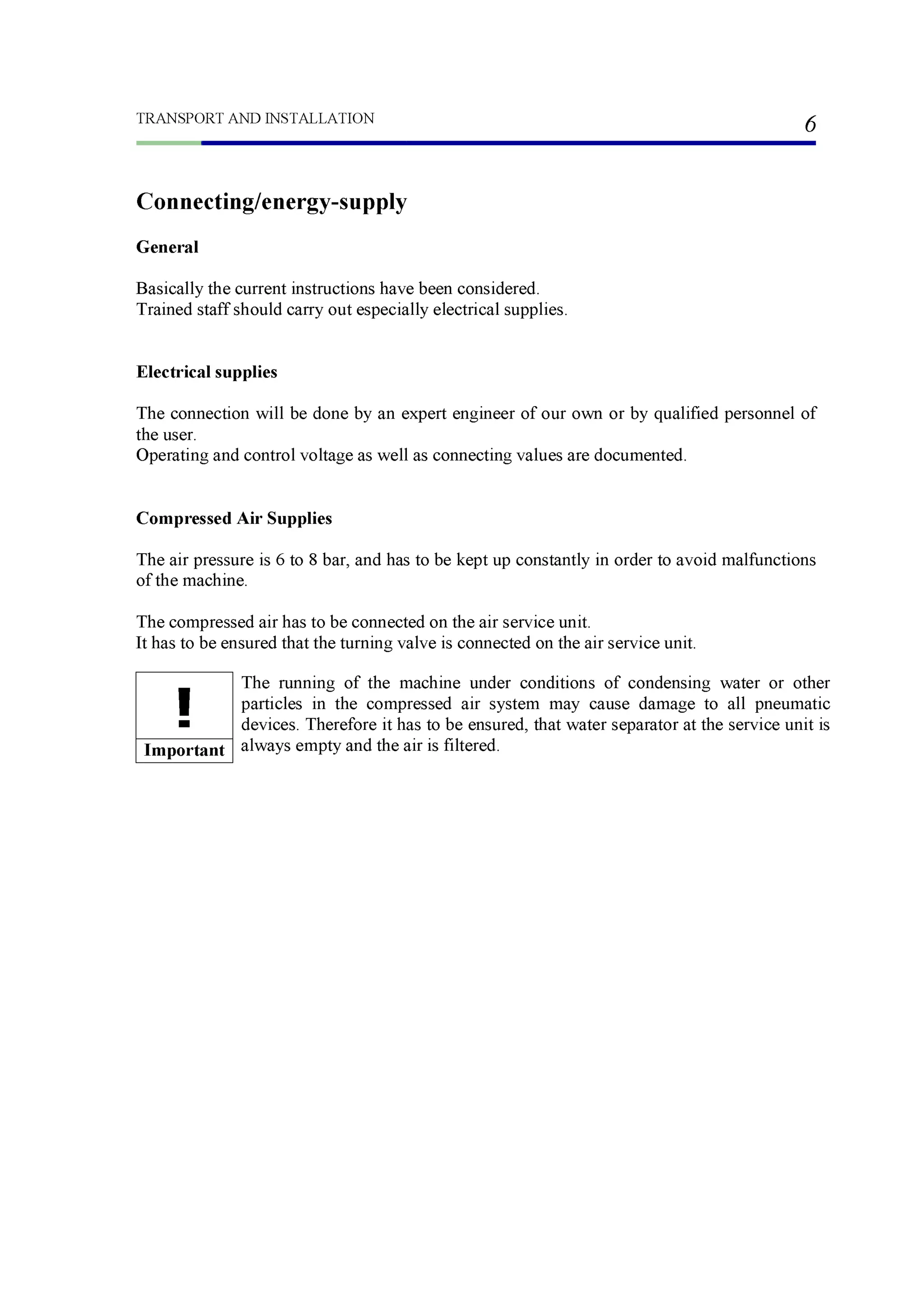
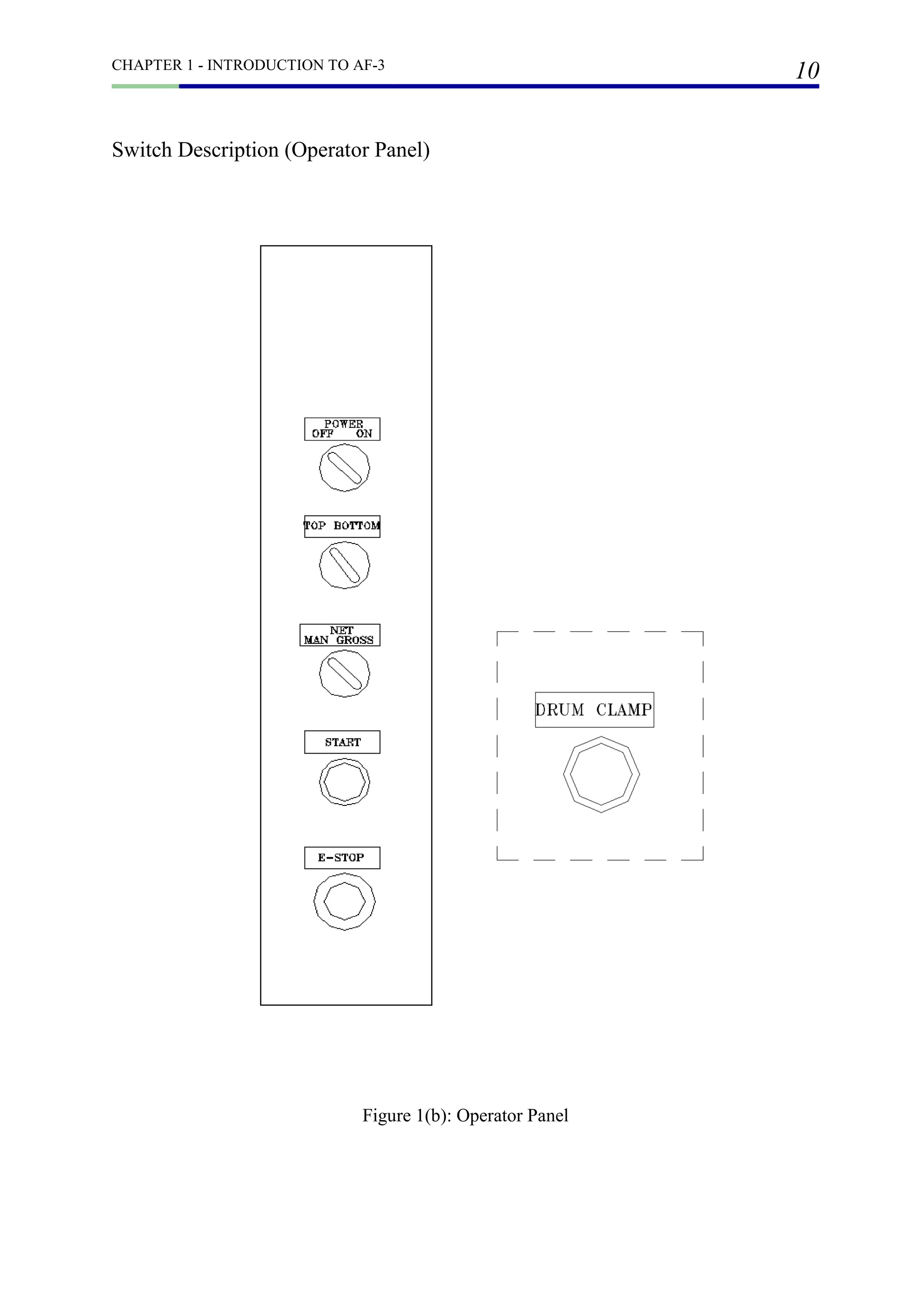
![(A) WEIGHING INDICATOR FUNCTION PARAMETER
CALF- DESCRIPTION SETTING
VALUE
F01 Weighing Unit 2
F02 Decimal Point Position 1
F03 Minimum Division 0.1
F04 Capacity 300.00
F05 Set Zero Range 10
F10 Tare and Zero at Unstable Weight Value 1
F11 Tare at Negative Gross 1
F14 Weighing Mode 1
FNCF- DESCRIPTION SETTING
VALUE
F02 Capabilities of [F] Key 0
F04 Display Content of Subdisplay Section 4
INF- DESCRIPTION SETTING
VALUE
INF-02 Capabilities of Input Terminal A2 2
INF-03 Capabilities of Input Terminal A3 9
INF-04 Capabilities of Input Terminal A4 10
CALIBRATION RELATED FUNCTION SETTING VALUE
BASIC CAPABILITIES FUNCTION RELATED SETTING VALUE
CONTROL I/O INPUT RELATED SETTING VALUE](https://image.slidesharecdn.com/af3-instructionmanual-cmspecialist-180919151900/75/Af3-instruction-manual-cm-specialist-57-2048.jpg)
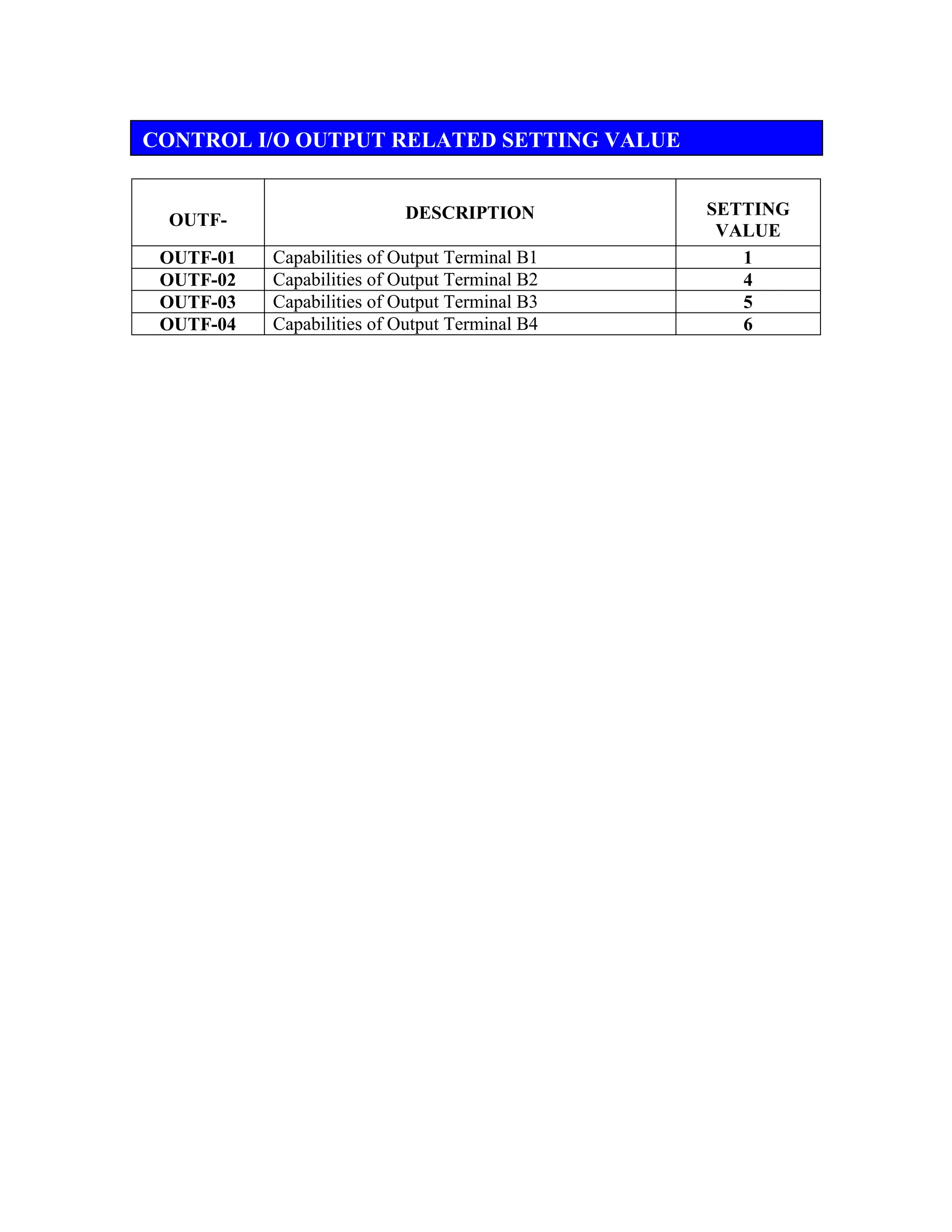

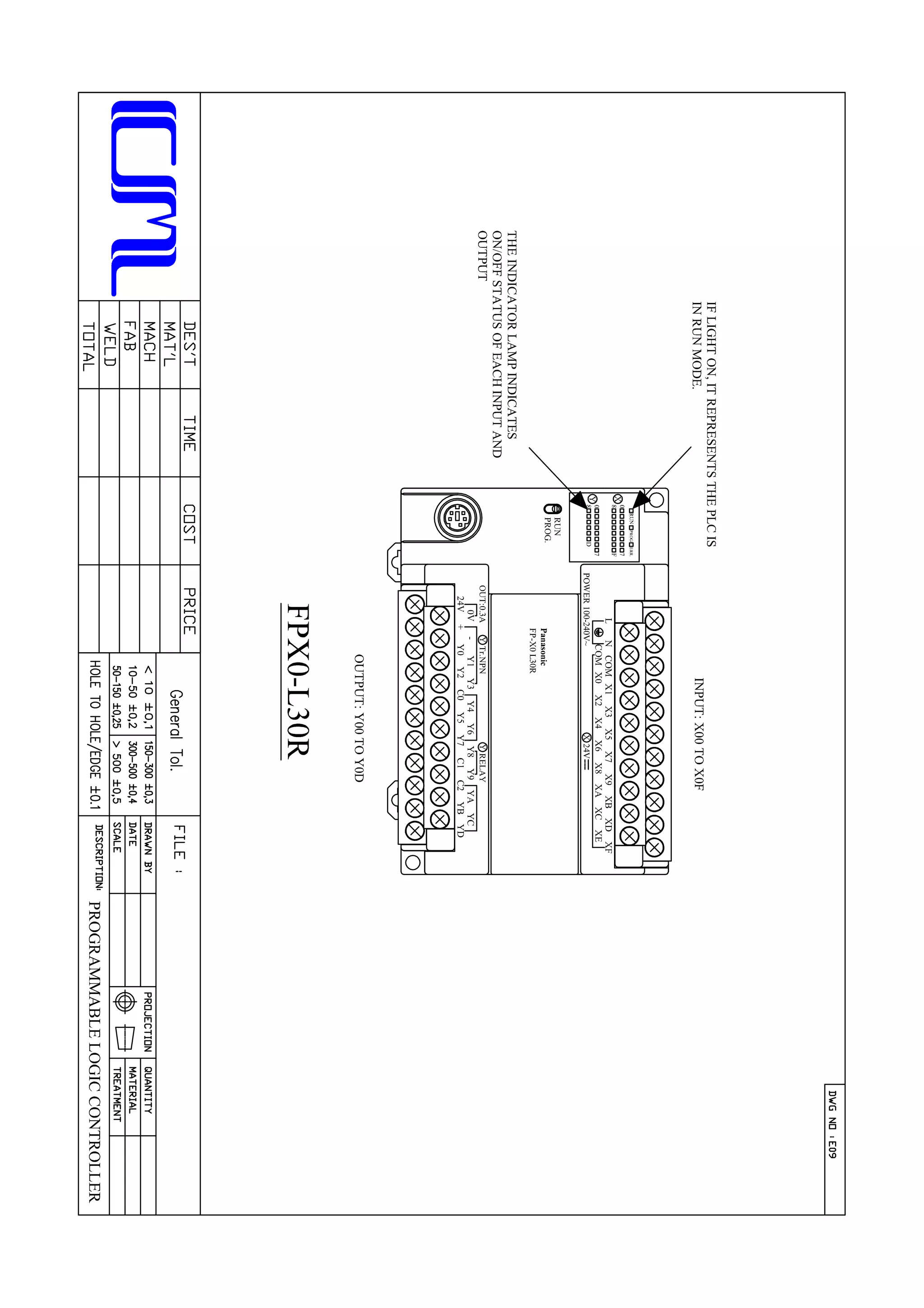
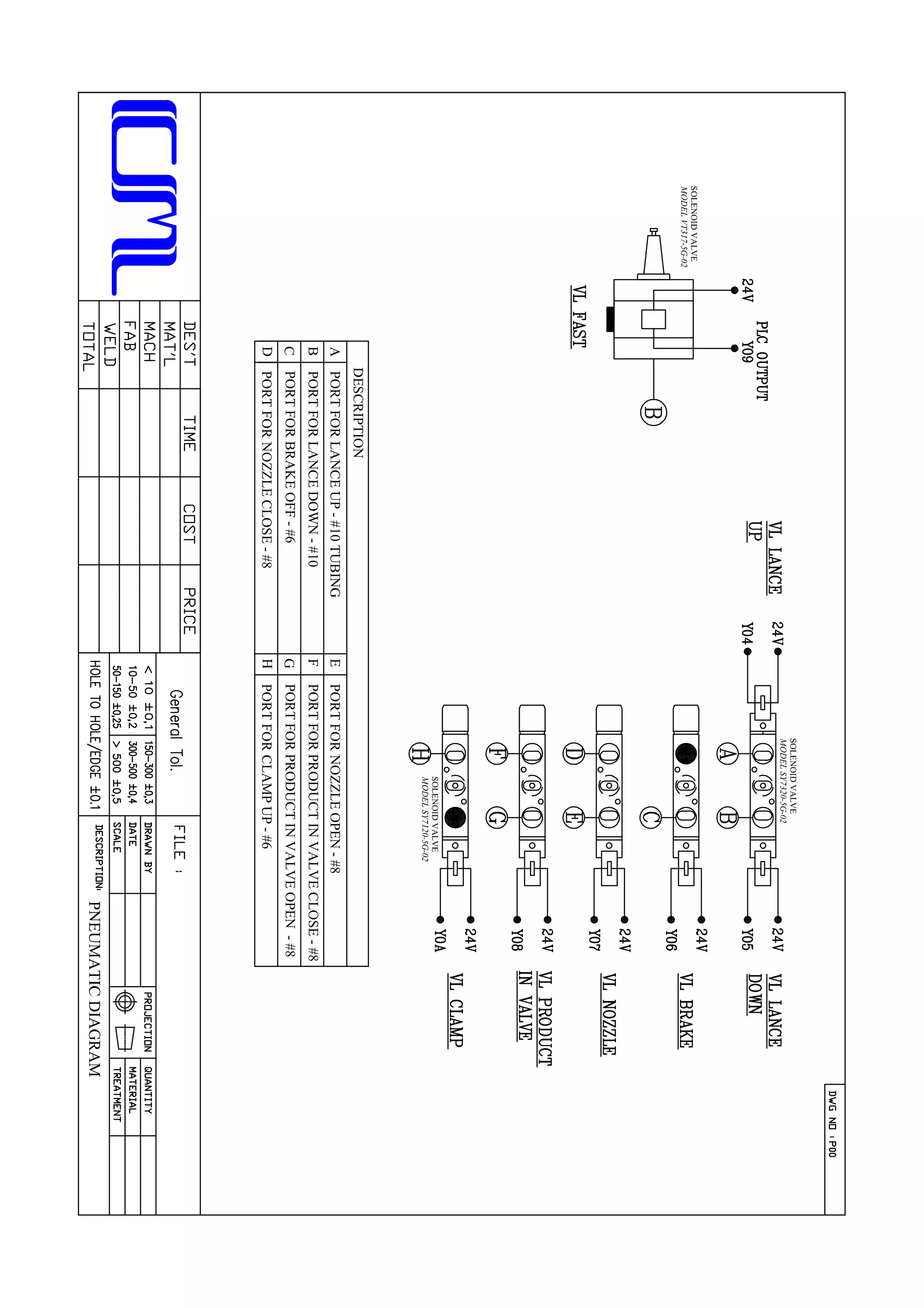
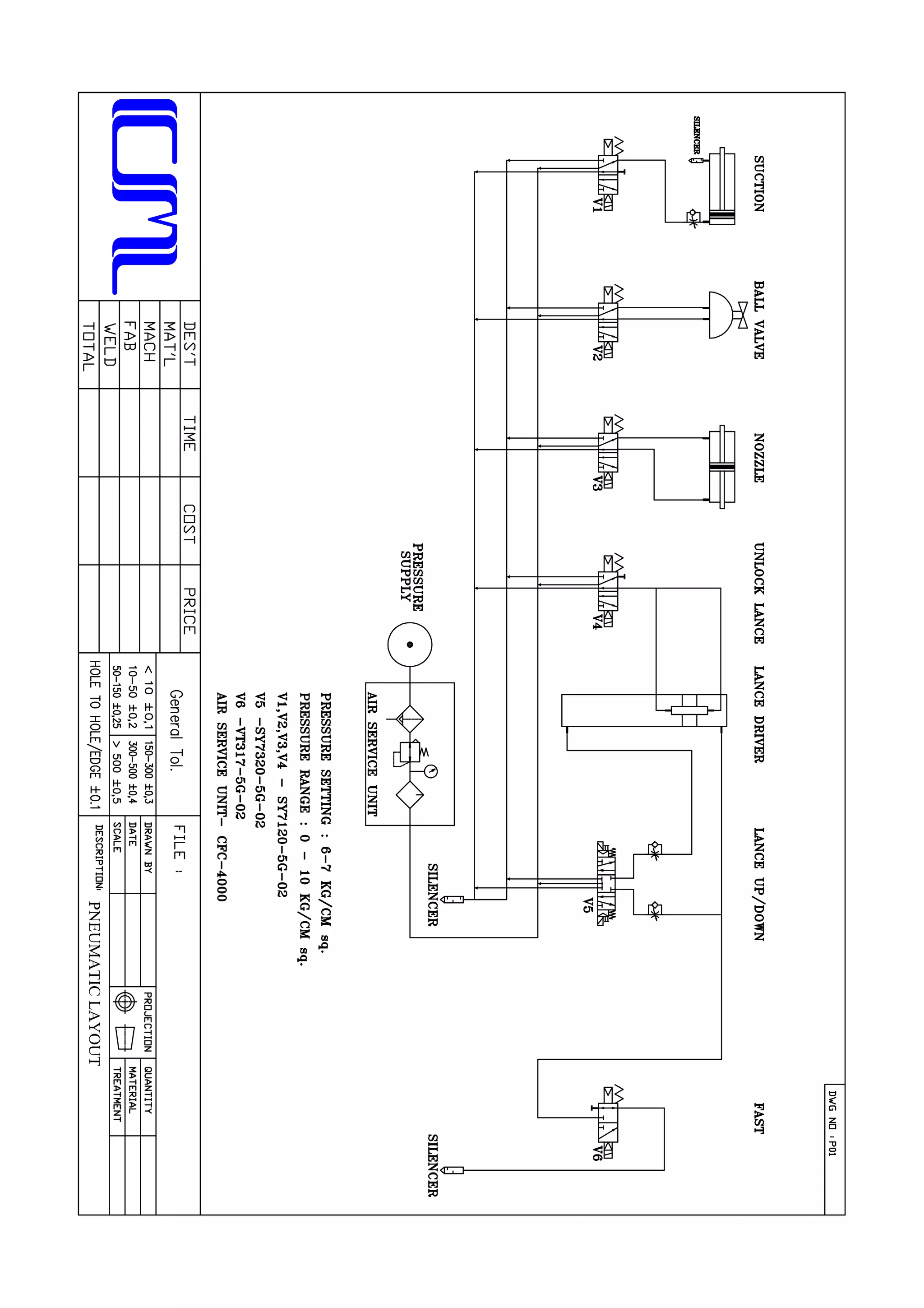
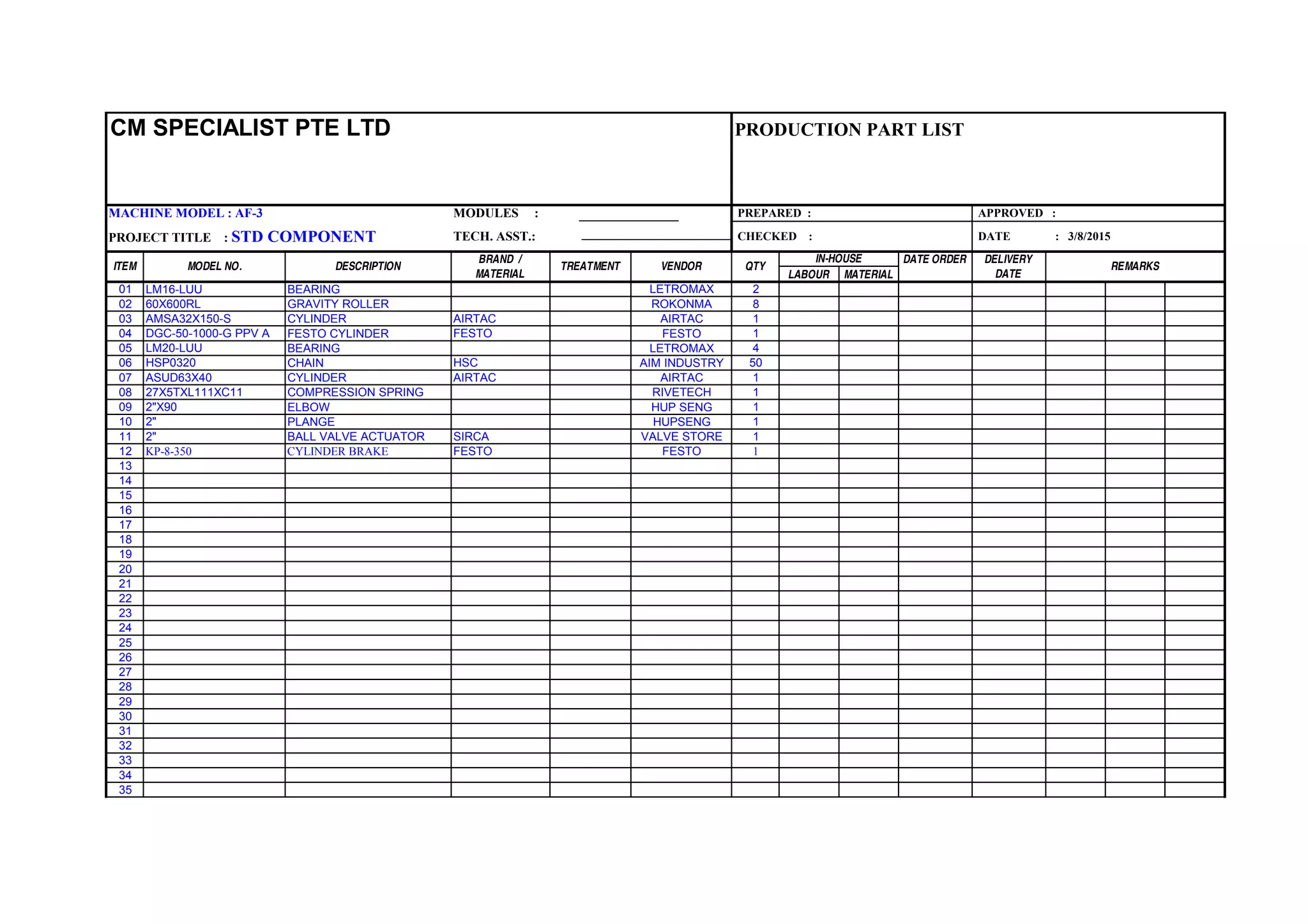
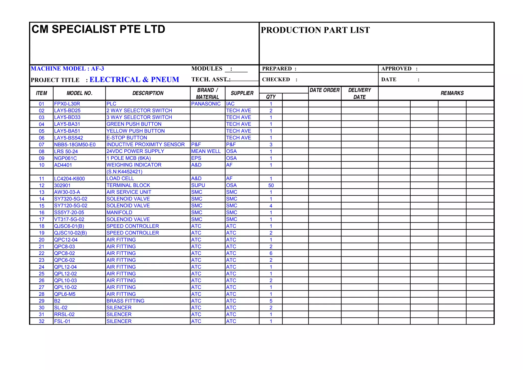
The document provides technical details and instructions for an AF-3 filling machine. It includes: - An overview of the machine components and operation procedures. - Safety guidelines for transport, installation, operation and maintenance. - Mechanical drawings of the major assemblies - load cell & drum clamp, nozzle, and structure - with part lists. - Electrical & pneumatic diagrams showing connections, wiring and functions. - Parameter settings for the weighing indicator and maintenance instructions.