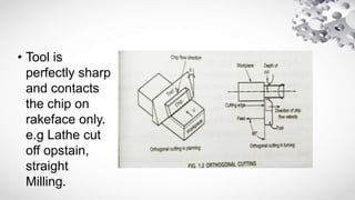
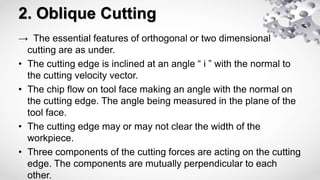
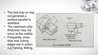
Orthogonal And Oblique
Cutting
Anil B. Aasodariya
150010119001
Production Technology
ME (02)
 Metal Cutting Process
→ In metal cutting process a sharp edged cutting tool is
made to cut the metal.
→ A tool must be harder than workpiece and it put in a
interference condition with workpiece.
→ By tool force metal comes in compression near the tool
tip, which produces shear-type deformation within the
metal.
→ In the metal cutting process, the tool is wedge-shaped and
has a straight cutting edge.
→ Basically, There are two type of methods of metal cutting
depending upon the arrangement of the cutting edge with
respect to the direction of relative work-tool motion.
→ There are two types of metal cutting methods as follow:-
1. Orthogonal Cutting & Two Dimensional Cutting
2. Oblique Cutting & Three Dimensional Cutting
1. Orthogonal Cutting
→ The essential features of orthogonal or two dimensional cutting
are as under.
• The cutting edge of the tool is perpendicular to the cutting
velocity vector.
• The direction of chip flow velocity is normal to the cutting edge.
• The cutting edge clear the width of the workpiece on either
ends. There is no side flow.
• Only two components of the cutting forces are acting on tool,
which are perpendicular to each other and can be represented
in a plane. (x,y)
• Tool is
perfectly sharp
and contacts
the chip on
rakeface only.
e.g Lathe cut
off opstain,
straight
Milling.
2. Oblique Cutting
→ The essential features of orthogonal or two dimensional
cutting are as under.
• The cutting edge is inclined at an angle “ i ” with the normal to
the cutting velocity vector.
• The chip flow on tool face making an angle with the normal on
the cutting edge. The angle being measured in the plane of the
tool face.
• The cutting edge may or may not clear the width of the
workpiece.
• Three components of the cutting forces are acting on the cutting
edge. The components are mutually perpendicular to each
other.
• The tool may or may
not generate a
surface parallel to
workface.
• The maximum chip
thickness may not
occur at the middle.
• Frequently, more
than one cutting
edges are in action.
e.g Faming, Milling.
Thank You

TYPES OF CUTTING

  • 1.
    Orthogonal And Oblique Cutting AnilB. Aasodariya 150010119001 Production Technology ME (02)
  • 2.
     Metal CuttingProcess → In metal cutting process a sharp edged cutting tool is made to cut the metal. → A tool must be harder than workpiece and it put in a interference condition with workpiece. → By tool force metal comes in compression near the tool tip, which produces shear-type deformation within the metal. → In the metal cutting process, the tool is wedge-shaped and has a straight cutting edge.
  • 3.
    → Basically, Thereare two type of methods of metal cutting depending upon the arrangement of the cutting edge with respect to the direction of relative work-tool motion. → There are two types of metal cutting methods as follow:- 1. Orthogonal Cutting & Two Dimensional Cutting 2. Oblique Cutting & Three Dimensional Cutting
  • 4.
    1. Orthogonal Cutting →The essential features of orthogonal or two dimensional cutting are as under. • The cutting edge of the tool is perpendicular to the cutting velocity vector. • The direction of chip flow velocity is normal to the cutting edge. • The cutting edge clear the width of the workpiece on either ends. There is no side flow. • Only two components of the cutting forces are acting on tool, which are perpendicular to each other and can be represented in a plane. (x,y)
  • 5.
    • Tool is perfectlysharp and contacts the chip on rakeface only. e.g Lathe cut off opstain, straight Milling.
  • 6.
    2. Oblique Cutting →The essential features of orthogonal or two dimensional cutting are as under. • The cutting edge is inclined at an angle “ i ” with the normal to the cutting velocity vector. • The chip flow on tool face making an angle with the normal on the cutting edge. The angle being measured in the plane of the tool face. • The cutting edge may or may not clear the width of the workpiece. • Three components of the cutting forces are acting on the cutting edge. The components are mutually perpendicular to each other.
  • 7.
    • The toolmay or may not generate a surface parallel to workface. • The maximum chip thickness may not occur at the middle. • Frequently, more than one cutting edges are in action. e.g Faming, Milling.
  • 8.