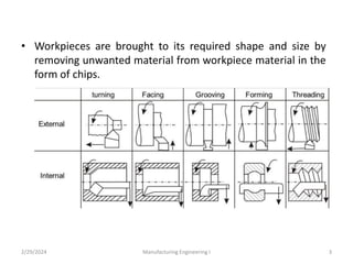
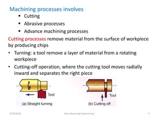
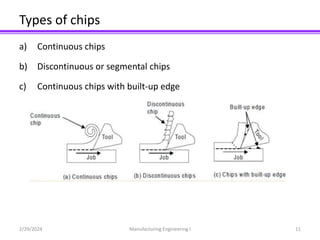
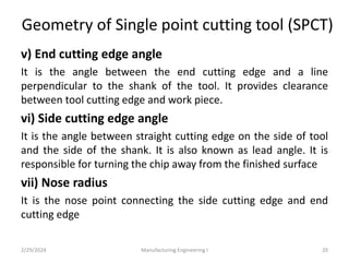
The document discusses traditional machining processes, detailing the mechanics of machining, types of machining operations, and chip formation mechanisms. It explains crucial aspects such as tool geometry, various cutting tools, and the forces involved in machining. Additionally, it covers tool wear, tool life, and the factors contributing to tool failure during operations.


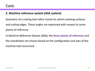


![3. Tool geometry in tool reference system
Orthogonal rake system (ORS) [also called ISO - old]
In ORS system configuration of tool geometry is taken as a reference
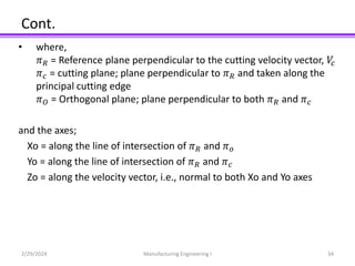
The planes of reference and the co-ordinate axes used for expressing
the tool angles in ORS are: 𝜋𝑅 − 𝜋𝑐 − 𝜋𝑜 𝑎𝑛𝑑 𝑋𝑂 − 𝑌𝑂 − 𝑍𝑂
2/29/2024 Manufacturing Engineering I 33](https://image.slidesharecdn.com/chapter220121st-240229153820-eb1f30db/85/Traditional-Machining-Processes-presentation-33-320.jpg)
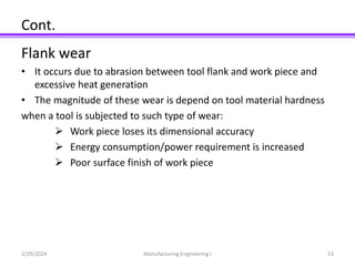
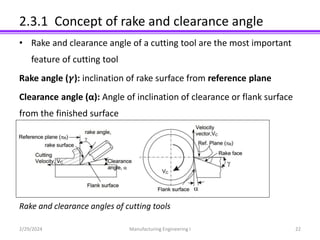
![Cont.
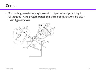
Definition of angles:
𝜸𝒐 = orthogonal rake: angle of inclination of the rake surface from
Reference plane, 𝜋𝑅 and measured on the orthogonal plane, 𝜋𝑜
λ = inclination angle; angle between 𝜋𝑐 from the direction of assumed
longitudinal feed [𝜋𝑋] and measured on 𝜋𝑐
𝛼𝑜= orthogonal clearance of the principal flank: angle of inclination of the
principal flank from 𝜋𝑐 and measured on 𝜋𝑜
2/29/2024 Manufacturing Engineering I 36](https://image.slidesharecdn.com/chapter220121st-240229153820-eb1f30db/85/Traditional-Machining-Processes-presentation-36-320.jpg)